Abstract
Timing chain tensioners are the elements whose damage may lead to serious failure of an engine. In addition, damage to the tensioner in a motorcycle engine may cause uncontrolled coming of the engine to a standstill, thereby putting the motorcyclist’s life or health at risk, should the timing chain break. The paper discusses the possibility of diagnosing damage to the timing chain tensioner in a motorcycle engine by means of the measurement, processing and analysis of vibration signals. The vibration generated by an engine equipped with a new, used and damaged tensioner was measured. By applying vibration signal processing by means of a continuous wavelet transform, the ranges of the rotational speed and the frequency scale were identified, for which monitoring of the condition of the timing chain tensioner should be conducted. Based on the tests performed, the quantitative and qualitative vibration symptoms of damage to the timing chain tensioner were identified.
1. Introduction
The ensuring of the reliable operation of means of transport requires continuous monitoring of their technical condition [1-16]. Newer and newer research methods using the measurement, processing and analysis of vibration signals are being currently developed to diagnose the technical condition of means of transport [17-39]. The sources of information include both the vibration and noise generated by means of transport. The application of these methods allows disassembly-free and often contactless determination of the technical condition. The vibroacoustic methods enable performing the measurements during regular operation, as well as detecting damage at an early stage of its development [11, 19]. Currently, a trend may be observed towards implementing the methods for the measurement and processing of vibroacoustic signals in the diagnostics of new objects [9, 10, 12, 24-26, 38, 40]. These include components of means of transport, such as combustion engines or new materials applied in the construction of means of transport.
Motorcycle combustion engines are drive units that are expected to operate safely and without failure [28-33, 41-46]. Ensuring their operational reliability is also essential for the cyclist’s comfort and safety, as the driver is in the immediate vicinity of the drive unit during movement. The motorcycle user intensly feels any change in the technical condition of the engine, for the vibration generated by the engine are transmitted directly to the other elements of the motorcycle [43]. Such a change also contributes to an increase of noisiness of the motorcycle [41, 44, 46].
Motorcycle engine maintenance operations used until now, whose aim is to detect damage or excessive wear of mechanical elements, reveal only major destructive changes in the engine. Diagnostics are based among others on the description of symptoms of damage by owners and are supported by local listening to an engine with a sounding rod. The application of new diagnostic tools which use measurements, processing and analyses of vibroacoustic signals of motorcycle engines should significantly expand the scope and accuracy of tests. These tools should enable detection of early cases of mechanical damage to these engines, e.g. periodic inspections of a motorcycle. Authors of other papers on the diagnostics of means of transport drew the same conclusions [11, 15, 18, 21-25, 28, 35, 37]. These activities may also help to stop further destructive processes which lead to serious failures of these engines.
The motorcycle engine elements which in certain models are subject to premature damage are tensioners in the timing chain system. Their damage is caused by the loss of tightness, which leads to a temporary drop of the required oil pressure in the tensioner. This causes a loss of smoothness of the timing chain operation leading, in consequence, to an increase of the motorcycle’s vibration and noisiness, as well as reduction of its power. In critical situations, such a damage may lead to breakage of the cam chain. The paper proposes the use of vibroacoustic methods to diagnose damage to the timing chain tensioner.
The development of methods of early and contactless detection of damage to the cam chain tensioner is also vital for another reason: it may protect the motorcycle user from unexpected blocking of the engine while the motorcycle is running.
This paper presents the initial results of research whose purpose was to assess the possibility of diagnosing damage to the hydraulic timing chain tensioner in a motorcycle’s combustion engine. For the diagnostics, methods for the measurement, processing and analysis of the recorded vibroacoustic signals were proposed.
2. Stand tests
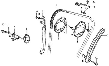
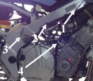
The research object was a Honda CBR 600 F2 motorcycle in a good technical condition, equipped with a combustion engine marked as PC 25 (Fig. 1). With a cam chain driven engine, the motorcycle was also equipped with two camshafts in the head (Fig. 2).
Fig. 1Location of the cam tensioner installation
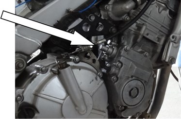
Fig. 2Simplified schematic diagram of the timing gear system
The element of the engine that is exposed to damage is the hydraulic chain tensioner, which shows a tendency for a momentary decrease of the required pressure caused by wear of its piston and sleeve (Fig. 3). As a result of using a damaged timing chain tensioner, the timing chain loses its tension to produce sagging, which manifests itself in the uneven work of the engine, its reduced power, and the possible instantaneous rubbing of the chain against the housing of the timing mechanism.
To assess the possibility of diagnosing damage to the timing chain tensioner using methods for the measurement and processing of the vibration signals, a new tensioner was installed in the engine, as well as a tensioner used for a longer period of time (in working order), and a damaged tensioner.
The measurement system used in the tests consisted of:
– an Ometron laser vibrometer (Fig. 4),
– 3 accelerometers (Fig. 5),
– a National Instrument Data Acquisition Card NI 4472,
– a computer with the LabView 8.6 software.
Signals were recorded at a frequency of 20 kHz. Matlab-Simulink Signal Processing software was used for processing.
Fig. 3View of the tensioner with a washer
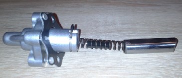
Fig. 4Laser vibrometer
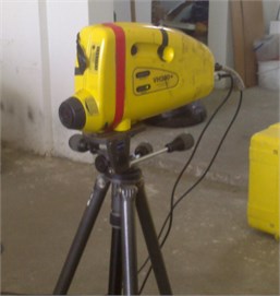
Fig. 5Distribution of measurement points: 1 – accelerometer no. 1, 2 – accelerometer no. 2, 3 – accelerometer no. 3, 4 – point of contactless measurement with a laser vibrometer
The measurements were made in the following conditions:
– coasting of the engine from a rotational speed of idling of ca. to 1,400 rpm to the maximum rotational speed,
– at the rotational speed of idling,
– at a rotational speed of ca. 2,500 rpm.
In assessing the possibility of applying the method of early damage detection for the timing chain tensioner in the motorcycle engine, the time-scale distributions of the vibration signal frequencies were determined by means of a continuous wavelet transform [47, 48] from the dependence:
where – scale parameter, – shift parameter, – analysed signal, – wavelet.
Based on the initial tests it was assumed that the calculation of the distributions would be conducted using the Daubechies 2 wavelet in the frequency-scale band of 2-20.
3. Test results and their analysis
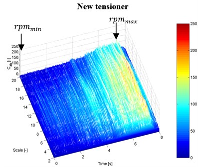
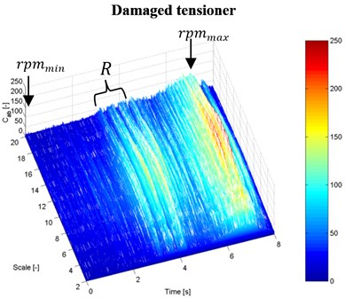
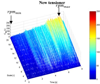
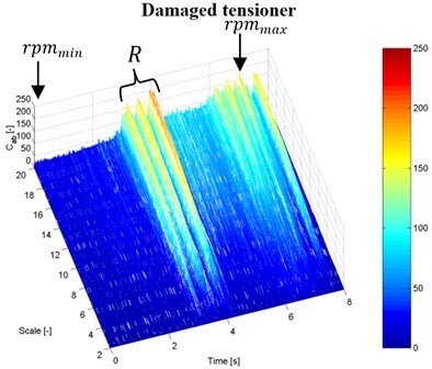
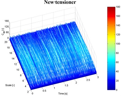
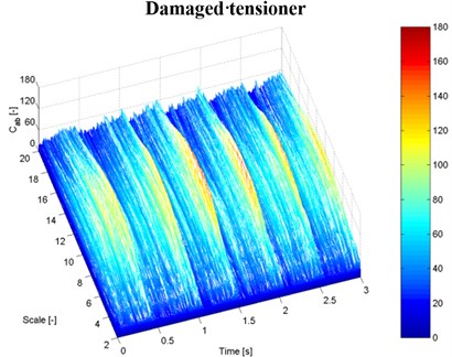
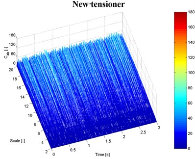
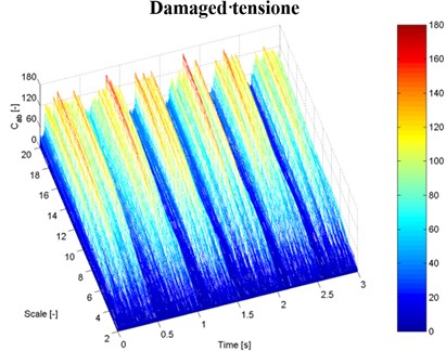
Fig. 6 presents some examples of the time-scale distributions of the vibration signal frequencies recorded during coasting of the engine in which a good and a damaged tensioner were installed.
As results from the obtained distributions in the frequency scale of 2-20, a local increase is observed in the vibration amplitude in the lowest range of the rotational speed, when the damaged tensioner was installed in the engine, which is marked in the figures as ““. In the evaluation of the condition of the engine, the range of this speed was identified as ca. 2,500 rpm. In that case resonance occurred in the timing mechanism, which was caused by the poor condition of the tensioner. However, it should be pointed out that although in the motorcycle engine a very fast increase in the rotational speed occurs during coasting, the identification of the resonance phenomena should be performed, however difficult it seems, at a slow increase of the rotational speed of the engine.
Fig. 6Time-scale distributions of the vibration signal frequencies at coasting of the motorcycle engine (rpm – rotational speed of the engine, R – the range of the rotational speed at which resonance occurs): a), b) vibration measurement with an accelerometer no. 1, c), d) vibration measurement with a laser vibrometer on the tensioner housing
a)
b)
c)
d)
By analysing the changes in the vibration amplitude values of the presented distributions it can be noted that the measurement of the vibration speed of the tensioner housing, taken using a laser vibrometer, shows a more explicit change in the vibration amplitude, which is a symptom of the incorrect work of the tensioner. The much higher sensitivity of measurements of this type is caused by the fact that they are made directly on the damaged component, and thus, the closest to the source of the generated vibration.
In further study, the changes in the vibration amplitude of an engine with a new and a damaged tensioner were analysed. Fig. 7 shows some examples of the vibration course at a rotational speed of 2,500 rpm.
When analysing the recorded vibration signals of the engine with a damaged tensioner, local maxima can be observed in the time distributions, which occur with a frequency of ca. 0.5 Hz for transducers 1-3 and ca. 80 Hz for the laser vibrometer. Such explicit changes in the vibration signals were not observed when analysing the signals recorded at the rotational speed of idling.
Further study focused on the influence of the technical condition of the tensioner on a change in the vibration level values. Fig. 8 presents the calculated Root Mean Square values (marked RMS) of the recorded vibration signals at the rotational speed of idling and at a speed of ca. 2,500 rpm.
Fig. 7The recorded vibration acceleration and speed signals at a rotational speed of 2,500 rpm
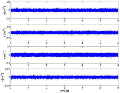
a) New tensioner
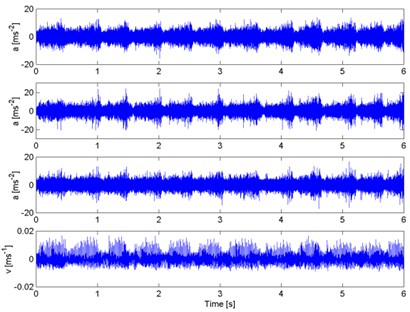
b) Damaged tensioner
Fig. 8RMS values of the recorded vibration acceleration and speed signals at the engine’s rotational speed of idling a) and at ca. 2,500 rpm b)
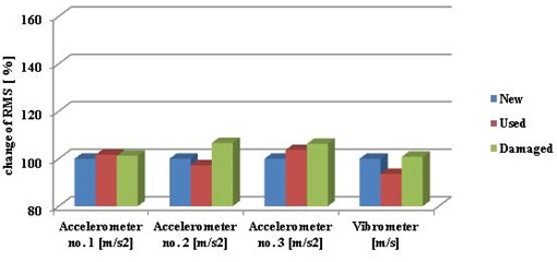
a)
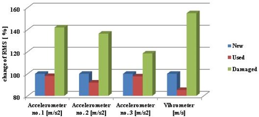
b)
At the rotational speed of idling the signals recorded by two transducers only showed an small increase in the vibration values caused by the damage to the tensioner. The highest increase in the level of engine vibration caused by damage of the tensioner occurs at a rotational speed of ca. 2,500 rpm. This change was recorded in each measurement point.
As part of the study, the influence was also analysed of the tensioner’s damage on the qualitative changes in the time-scale CWT distributions of the frequency at a constant rotational speed of 2,500 rpm. Fig. 9 presents examples of the time-scale CWT frequency distributions for engines with a new and damaged tensioner. The measurement was performed with transducer 1 and with a laser placed on the housing of the tensioner.
For the purpose of a qualitative evaluation of the changes occurring in the above-mentioned distributions, their effective values were determined. The calculations were made on the basis of averaged distributions in the frequency scale domain from the dependence:
where: – time-scale frequency wavelet distribution of the vibration signal, – scale parameter, – shift parameter, – lower range of the frequency scale, – upper range of the frequency scale.
Fig. 9Examples of time-scale signal frequency distributions for the vibration recorded at a constant speed of 2,500 rpm: a), b) vibration measurement with an accelerometer no. 1, c), d) vibration measurement with a laser vibrometer on the tensioner housing
a)
b)
c)
d)
The results of the calculations provided in Table 1 show explicitly that the adopted range of the frequency scale and of the rotational speed of the engine includes information about the change in the technical condition of the tensioner, and the diagnosing of the damage should be conducted in such a range.
Table 1Change of RMS value of time-scale frequency distributions
RMS of [-] | 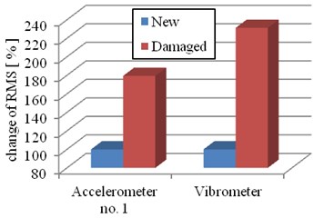 | ||
Measurment | New | Damaged | |
Accelerometer no. 1 | 13,08 | 23,47 | |
Vibrometer | 5,8 | 13,41 | |
4. Conclusions
Motorcycle engines require the development of measurement systems which do not require disassembling them, and methods of automatic diagnostics of damage and excessive wear of mechanical elements. A change in the technical condition of mechanical elements of these engines contributes, among others, to an increase in clearances and, in numerous cases, to an increase in vibration and noise. According to the research presented in [2, 5, 16-19, 23-25, 37] and the author's own studies [4, 21, 36], the application of methods of measurement, processing and analysis of vibroacoustic signals can be useful in diagnostics in such cases.
The experimental research described in this paper makes it possible to conclude that application of vibration measurements and processing their results enable diagnosing damage to the hydraulic cam chain tensioner in the motorcycle engine. The results of an analysis of time-scale distributions of the frequencies of vibration signals recorded when accelerating an engine indicate that damage to a timing chain tensioner causes vibration resonance at a speed of ca. 2500 rpm. Quantitative and qualitative changes of the vibration signal in the rotational speed range of the engine within which resonance occurs allow drawing conclusions as to the condition of the tensioner and deciding about its possible replacement. In this case, the use of systems having the capacity to measure and analyse vibration signals to monitor the motorcycle engine may enhance the operational reliability and safety of the motorcycle.
References
-
Urbanek J., Barszcz T., Antoni J. Time-frequency approach to extraction of selected second-order cyclostationary vibration components for varying operational conditions. Measurement: Journal of the International Measurement Confederation, Vol. 46, Issue 4, 2014, p. 1454-1463.
-
Haniszewski T., Gaska D. Overhead traveling crane vibration research using experimental wireless measuring system. Transport Problems, Vol. 8, Issue 1, 2013, p. 57-66.
-
Akitsu Y. Research on engine torque control with acceleration performance for MotoGP class racing motorcycles. SAE Technical Papers 4.
-
Figlus T., Wilk A., Krajzel K. The influence of drive parameters and technical condition on the vibroactivity of devices with single-cylinder internal combustion engines. Transport Problems, Vol. 8, Issue 1, 2013, p. 79-85.
-
Droździel P., Krzywonos L. The estimation of the reliability of the first daily diesel engine start-up during its operation in the vehicle. Eksploatacja i Niezawodność – Maintenance and Reliability, Vol. 41, Issue 1, 2009, p. 4-10.
-
Droździel P., Krzywonos L., Madlenak R., Rybicka I. Selected aspects of analyses of failure rates of active safety systems in buses. Komunikacie, Vol. 16, Issue 3, 2014, p. 114-119.
-
Madleňák R., Madleňáková L., Pavličko M. Postal Transportation Network: Design and Construction. Žilina. Žilinská Univerzita, 2014, p. 236.
-
Wei H., Li Z., Liang X., Shu G. Influence of the accelerating operation mechanism on the combustion noise in DI-diesel engines. International Journal of Automotive Technology, Vol. 13, Issue 3, 2012, p. 373-388.
-
Młyńczak J. Using databases in switch point mechanism diagnostics. Communications in Computer and Information Science, Vol. 104, 2010, p. 152-159.
-
Hamacek Š., Bartłomiejczyk M., Hrbáč R., Mišák S., Stýskala V. Energy recovery effectiveness in trolleybus transport. Electric Power Systems Research, Vol. 112, 2014, p. 1-11.
-
Dabrowski Z., Zawisza M. Investigations of the vibroacoustic signals sensitivity to mechanical defects not recognised by the OBD system in diesel engines. Solid State Phenomena, 2011, p. 194-199.
-
Gajdzik B., Wieszała R. Measurements of the communication noise level on the internal roads of the manufacturing metallurgical enterprise. Metalurgija, Vol. 51, Issue 3, 2012, p. 369-372.
-
Burdzik R., Konieczny Ł., Adamczyk B. Automatic control systems and control of vibrations in vehicles car. Communications in Computer and Information Science, Vol. 471, 2014, p. 120-129.
-
Rodopoulos K., Yiakopoulos C., Antoniadis I. A parametric approach for the estimation of the instantaneous speed of rotating machinery. Mechanical Systems and Signal Processing, Vol. 44, Issues 1-2, 2014, p. 31-46.
-
Michalski R., Wierzbicki S. An analysis of degradation of vehicles in operations. Eksploatacja i Niezawodność – Maintenance and Reliability, Vol. 1, Issue 37, 2008, p. 30-32.
-
Deuszkiewicz P., Radkowski S. On-line condition monitoring of a power transmission unit of a rail vehicle. Mechanical Systems and Signal Processing, Vol. 17, Issue 6, 2003, p. 1321-1334.
-
Shatnawi Y., Al-Khassaweneh M. Fault diagnosis in internal combustion engines using extension neural network. IEEE Transactions on Industrial Electronics, Vol. 61, Issue 3, 2014, p. 1434-1443.
-
Czech P., Łazarz B., Wojnar G., Matyja T., Dabrowski Z. Application of the discrete wavelet transform and probabilistic neural networks in Si engine valve fault diagnostics. 20th International Congress on Sound and Vibration, Vol. 1, 2013, p. 843-848.
-
Urbanek J., Barszcz T., Zimroz R., Antoni J. Application of averaged instantaneous power spectrum for diagnostics of machinery operating under non-stationary operational conditions. Measurement: Journal of the International Measurement Confederation, Vol. 45, Issue 7, 2012, p. 1782-1791.
-
Barczewski R., Jakubek B. Problems of in-situ vibroacoustic testing of low-vibroactive devices. Vibrations in Physical Systems, Vol. 25, 2012, p. 59-64.
-
Figlus T., Liščák Š., Wilk A., Łazarz B. Condition monitoring of engine timing system by using wavelet packet decomposition of a acoustic signal. Journal of Mechanical Science and Technology, Vol. 28, Issue 5, 2014, p. 1663-1671.
-
Dziurdź J. Application of correlation and coherence functions in diagnostic systems. Diffusion and Defect Data Pt.B: Solid State Phenomena, Vol. 196, 2013, p. 3-12.
-
Burdzik R., Węgrzyn T., Konieczny Ł., Lisiecki A. Research on influence of fatigue metal damage of the inner race of bearing on vibration in different frequencies. Archives of Metallurgy and Materials, Vol. 59, Issue 4, 2014, p. 1275-1281.
-
Czech P., Madej H. Application of cepstrum and spectrum histograms of vibration engine body for setting up the clearance model of the piston-cylinder assembly for RBF neural classifier. Eksploatacja i Niezawodność – Maintenance and Reliability, Vol. 4, Issue 52, 2011, p. 15-20.
-
Albarbar A., Ball A., Starr A. On acoustic measurement based internal combustion engines condition monitoring. Insight: Non-Destructive Testing and Condition Monitoring, Vol. 50, Issue 1, 2008, p. 30-34.
-
Liu J.-M., Li H.-Y., Qiao X.-Y., Li X.-L., Shi Y.-P. Engine cylinder pressure identification method based on cylinder head vibration signals. Neiranji Gongcheng/Chinese Internal Combustion Engine Engineering, Vol. 34, Issue 4, 2013, p. 32-37.
-
Sun Y.-Q., Wang B., Zhang Y.-T., Li Z.-N., Zhang G. Study of fault diagnosis of diesel engine fuel injection based on adaptive parallel factor. Binggong Xuebao/Acta Armamentarii, Vol. 34, Issue 5, 2013, p. 519-526.
-
Antoni J., Ducleaux N., Nghiem G., Wang S. Separation of combustion noise in IC engines under cyclo-non-stationary regime. Mechanical Systems and Signal Processing, Vol. 38, Issue 1, 2014, p. 223-236.
-
Tsai H.-C., Gao B.-Y., Chiang M.-H., Chen B.-C., Wu Y.-Y. Misfire diagnostic strategy for motorcycles. SAE Technical Papers, Vol. 2013, 2013.
-
Gryllias K. C., Antoniadis I. A. Estimation of the instantaneous rotation speed using complex shifted Morlet wavelets. Mechanical Systems and Signal Processing, Vol. 38, Issue 1, 2013, p. 78-95.
-
Periyasamy S., Alwarsamy T. Analysis of block vibrations induced by combustion chamber pressure in a diesel engine. Journal of Vibroengineering, Vol. 14, Issue 1, 2012, p. 250-259.
-
Kaul S., Dhingra A. K. Engine mount optimisation for vibration isolation in motorcycles. Vehicle System Dynamics, Vol. 47, Issue 4, 2009, p. 419-436.
-
De Falco D., Di Massa G., Pagano S., Strano S. Motorcycle handlebar dynamic response: theoretical and experimental investigation. International Review of Mechanical Engineering, Vol. 7, Issue 5, 2013, p. 795-801.
-
Yu G. B., Zhao Y., Nie J. F., Dai B., Song X. W. Gearbox fault diagnosis research based on wavelet transform. Applied Mechanics and Materials, Vol. 274, 2013, p. 233.
-
Sawalhi N., Randall R. B. Gear parameter identification in a wind turbine gearbox using vibration signals. Mechanical Systems and Signal Processing, Vol. 42, Issue 1-2, 2014, p. 368-376.
-
Figlus T., Stańczyk M. Diagnosis of the wear of gears in the gearbox using the wavelet packet transform. Metalurgija, Vol. 53, Issue 4, 2014, p. 673-676.
-
Dybala J., Zimroz R. Rolling bearing diagnosing method based on empirical mode decomposition of machine vibration signal. Applied Acoustics, Vol. 77, 2014, p. 195-203.
-
Ragulskis M., Maskeliunas R. Measurement of transverse vibrations of piezoelectric ceramics by atomic force microscopy. Experimental Techniques, Vol. 30, Issue 2, 2006, p. 37-41.
-
Pankiewicz J., Deuszkiewicz P., Dziurdź J., Zawisza M. Modeling of powertrain system dynamic behavior with torsional vibration damper. Advanced Materials Research, Vol. 1036, 2014, p. 586-591.
-
Matyja T. Simulink library project for modeling and simulation of dynamic phenomena in rotating power transmission systems. Transport Problems, Vol. 9, Issue 2, 2014, p. 101-110.
-
Carley M., Kennedy J., Walker I., Holt N. The experimental measurement of motorcycle noise. Proceedings of Meetings on Acoustics, Vol. 12, 2011, p. 040002.
-
Mohite U., Bhavsar P. A unified approach for prediction and control of motorcycle vibration subjected to engine dynamic force. SAE Technical Papers, Vol. 2, 2010.
-
Agostoni S., Cheli F., Leo E., Pezzola M. An innovative multi dof TMD system for motorcycle handlebars designed to reduce structural vibrations and human exposure. Mechanical Systems and Signal Processing, Vol. 31, 2012, p. 298-315.
-
Sun L., Shu G. The analysis for the influence of engine excitation on the dynamical behavior of motor vehicle. Applied Mechanics and Materials, Vol. 197, 2012, p. 179-184.
-
Taguchi T., Aoki M., Katsukawa Y., Koga M., Koshimizu T., Saitou M. Development of a noise prediction technique for designing a high-performance muffler of motorcycle. SAE Technical Papers, 2010.
-
Keliang C., Yonggang X., Shun L., Tianjun X. Study on controlling and forecasting noise radiated from engine. Applied Mechanics and Materials, Vol. 271, 2013, p. 1649-1653.
-
Mallat S. A Wavelet Tour of Signal Processing, 2nd Edition. Academic Press, 1999.
-
Misiti M., Misiti Y., Oppenheim G., Poggi J. Wavelet Toolbox for Use with MATLAB, MathWorks, 1996.
About this article

