Abstract
The study aims to deal with a suspension system whose main function is to isolate and absorb the impact from road surface to vehicle body. To provide good riding comfort, a damper with variable and wide-range damping is highly essential. In this study a magnetorheological (MR) damper with multiple poles is developed. This new designed variable-damping damper is totally different from those conventional constant-damping hydraulic dampers, and even different from common single-pole MR dampers. The range of damping force for this new MR damper is also effectively extended. Simulation of magnetic flux and field has been done in the study to provide an optimal structure of the damper which significantly enhances the damping force while avoiding magnetic saturation. After the dynamic test for the MR damper, experimental results show that the provided damping force can be significantly increased with the increase of input current from low to high speeds. Damping force can be varied by 7.41 times. It proves that this new MR damper with high damping force can be controlled adaptively at wide range of operation conditions. It is suitable to be an adaptively variable damping source in semi-active suspension systems or other applications.
1. Introduction
Suspension system is composed of springs and shock absorbers to support car body and axles. It can improve the car drivability, durability of vehicles and riding comfort during driving. Modern suspension is made of springs, shock absorbers and stabilizers. This mechanism can alleviate the vibration and impacts from the surface of roads between the car body and axles. Besides, it will reduce the car tilt and further improve the drivability and riding comfort of vehicles. However, the setting of shock absorber damper can affect the vehicle drivability and riding comfort significantly.
When vehicles change lanes or make turns, mass inertia will make vehicle itself incline and difficult to control. Moreover, large damping force from shock absorbers can decrease the rolling motion of vehicles and increase drivability. When vehicles run slowly on smooth and straight road, vehicles are relatively easy to control. At this time, small damping force of shock absorbers can enhance riders’ comfort. It is essential to augment the damping force of shock absorbers to increase vehicle stability while driving fast on the smooth straight road. However, it will reduce riders’ comfort. Thus, it is difficult for the setting of damping of shock absorber to take both vehicle drivability and riders’ comfort into consideration.
Therefore, shock absorbers with variable-damping dampers can adjust its damping value of shock absorbers in real time aim according to vehicle speed and road surface. If they are applied to the semi-active suspension system, they will handle car drivability and riding comfort into account together. Recently, the development of shock absorbers with adaptable dampers has been more and more emphasized.
Controllable magnetorheological (MR) damper adopts MR fluid to vary its damping characteristic. MR fluid has highly changeable viscosity. In MR fluid magnetic particles suspend in a carrier fluid [1-4]. Under an applied magnetic field, those magnetic particles will be chained together to form chain connections along the direction of the applied magnetic field. The higher the magnetic field is, the more stable the chains become and the higher the viscosity is. When the magnetic field is revomed, the MR fluid immediately returns to its free flow state. The response time of the fluid adapted to the change of magnetic field stays between 0.1-1 ms [5, 6]. Therefore, MR fluid is called intelligent material with changeable viscosity as a variable magnetic field applied.
For the applications of MR device, there are at least three operation modes for MR fluid: valve mode, direct shear mode, and squeeze mode (Fig. 1). In an MR damper, the MR fluid operates under a valve mode. As seen in Fig. 1(a), MR fluid is placed between a pair of stationary poles. The fluid flow is resisted by controlling the magnetic field between the poles, in a direction perpendicular to the flow.
Fig. 1Three operation modes of MR fluids
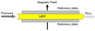
a) Valve mode
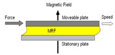
b) Direct shear mode
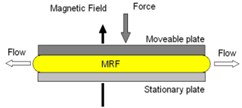
c) Squeeze mode
Fig. 2Concept structure of conventional damper
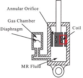
Fig. 3Magnetic flux of the piston in a conventional MR damper
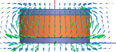
Fig. 4Magnetic field of the piston in a single-pole MR damper
Conventional MR dampers feature a single-pole structure as seen in Fig. 2 [7]. Commonly, the magnetic pole is surrounded by a coil placed on the piston assembly. The magnetic flux will flow following the loop marked by red color in Fig. 2. As a result, part of MR fluid around the cylindrical shape of the piston is being activated when magnetic field is applied. However, this design has two disadvantages. The first one is a very small area of MR fluid to be employed to create viscous resistance, as seen in Fig. 3. The second one is the uneven distribution of magnetic field strength on the active area. Those two major disadvantages reduce the overall damping force of a conventional MR damper.
Fig. 4 shows the magnetic field in damper piston. It is clear that the magnetic field penetrate the layer of MR fluid normally only on the upper and bottom ring areas of the piston, which are the active chaining areas for MR fluid. Conversely, the large middle ring area becomes non-active chaining area because the magnetic flux is parallel to the layer of MR fluid, not cross the layer. Therefore, tiny chain effect occurs in the middle ring area, and thus low viscous force can be obtained.
2. New MR damper with multi-pole piston
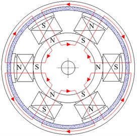
To enhance the damping characteristics of a MR damper, the area of active MR fluid must be enlarged. The multiple-pole concept is first proposed by Shiao’s study [8-9]. It uses multiple magnetic poles which form a cylindrical block of the piston of the damper (Fig. 5). Number of poles can be any of even numbers, i.e., 4 poles or 6 poles. Fig. 6 shows the pole arrangement and the flow of magnetic flux in red lines. The direction of magnetic flux in each pole is opposite to that of its two adjacent magnetic poles. As a result, the flux will travel in a closed loop: from one pole, through the MR fluid gap, into the rotor, back to the MR gap and into the two adjacent poles. By such a novel and unique design, the produced magnetic flux will orthogonally penetrate all the MR fluid in the channel between the cylindrical surface of the damper piston and the damper cylinder. Then a yield resistance is produced after applying current. From the operating concept, the head area of each pole mainly affects to activate the MR fluid area in the channel. Depending on the piston size, coil winding and manufacture abilities, different arrangements and numbers of poles can be chosen, from simple four-pole damper to more complex systems with more poles. Due to the manufacturing cost, a four-pole MR damper was simulated, analyzed and experimented in this study. The corresponding shear stress on the cylindrical surface of the piston is increased significantly and distributed evenly, which helps to enhance the damping force.
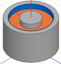
Fig. 5Structure and magnetic flux of multiple-pole piston in MR damper
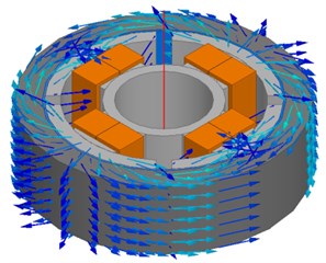
Fig. 6Operation concept for the multiple-pole piston in MR damper
Some parameters of the damping block for the new damper is shown in Table 1 with the selected dimensions referred to the traditional motorcycle damper. The magnetic simulation model is built based on these specifications. MRF-132DG fluid from LORD company was used as the MR fluid.
Table 1Specifications of the damping block
Outer diameter (mm) | Number of turns (turns) | Pole gap (mm) | |
Dimension | 27 | 100 | 3.44 |
2.1. Models of damping force
Damping force from the multi-pole MR damper can be calculated by Eq. (1) [10], where the first component is the controllable force. The yield stress is the yield stress from MR fluid under applied magnetic field:
In this study, MRF-132DG was used as the MR fluid. The B-H curve of MRF-132DG, which is used later in magnetic simulation, is in Fig. 7, while its relation of the yield stress of the MR fluid versus magnetic field strength is shown in Fig. 8.
Fig. 7B-H curve of MRF-132DG MR fluid [11]
![B-H curve of MRF-132DG MR fluid [11]](https://static-01.extrica.com/articles/15926/15926-img10.jpg)
Fig. 8Yield stress vs. magnetic field for MRF-132DG MR fluid [11]
![Yield stress vs. magnetic field for MRF-132DG MR fluid [11]](https://static-01.extrica.com/articles/15926/15926-img11.jpg)
2.2. Magnetic simulation and optimization
Magnetic simulation was conducted based on 4-pole design which is suitable for the current size of the damper. The target of damper optimization is to get a maximum MR damping force under fixed damper size and input current. Since inner and outer piston radii and gap between two adjacent poles are key factors to affect value of damping force, different value sets of these three variables were chosen during optimal process to get maximal damping force. The ranges (or constraints) of these three variables are listed in Table 2. A built-in Sequential Nonlinear Programming (SNLP) optimizer can perform the optimization automatically. The SNLP optimizer starts searching for optimal damping force from initial value set of the three variables, and runs FEM magnetic simulation to find damping force. According to the level of simulated damping force, the optimizer then chooses another value set and runs FEM again to find next damping force [8]. Such a procedure iterates many times to find an optimal value set which can result in maximum damping force. Fig. 9(a) shows the MR damping force for those 100 iterations, while Fig. 9(b) shows those 100 simulated MR damping forces for the range of gap variable. Since this optimization is constrained by the variable values in Table 2, the obtained optimal damping force is a local optimum for the damper.
The optimal values of different parameters to produce maximum damping force are shown in Table 3. This data then is used for manufacture of a new MR damper.
Table 2Optimization parameters
Parameters | Inner piston radius (mm) | Outer piston radius (mm) | Gap between two adjacent poles (mm) |
Range | 5-6 | 28-29 | 5-14 |
Table 3Optimal value of the new MR damper
Parameters | Inner piston radius (mm) | Outer piston radius (mm) | Gap between two adjacent poles (mm) |
Range | 5.89 | 28.54 | 8.35 |
Fig. 9a) Solution for the design variables and b) the cost function of the optimization problem
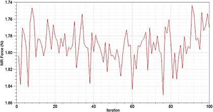
a)
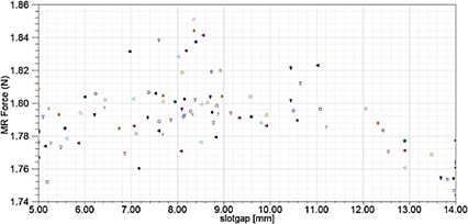
b)
The magnetic field characteristics of the optimal MR damper are shown in Fig. 10. In the figure, the direction of the magnetic flux in the cross-section of the MR brake is plotted. Its flow direction is noticeable as a closed loop from one pole on the piston, through the MR gap to the outer cylinder of the damper, then back through the MR gap again to the adjacent poles.
Fig. 10Flow directions of magnetic flux in a 4-pole MR damper piston
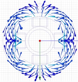
Fig. 11Magnetic field strength for the 4-pole MR damper piston
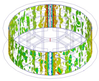
The magnitude of the magnetic field strength in the middle cross-section of the MR brake can be seen in Fig. 11. The maximum magnetic field strength, around 100 kA/m, occurs on the cylindrical pole head near the gap between two adjacent poles that is marked in red color. The area of pole-head shows an even magnetic field strength, which is better distribution than conventional MR dampers. The magnetic field strength, which helps to observe the damping motion of the piston, is the sources of high-yield stress.
3. Test of the new MR damper
3.1. Design and manufacturing of MR damper
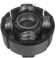
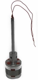
Fig. 12 shows the explosive view and assembly view for the piston block in multi-pole MR damper. The manufactured MR damper is shown in Fig. 13. The 4 coils are connected in series and the two main electric wires are put in the piston rod. This damper later was used in the experiment.
Fig. 12Explosive and assembly views of the piston
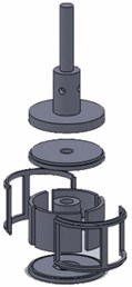
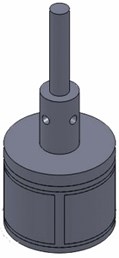
Fig. 13Manufactured piston and piston block
3.2. MR damper experiment
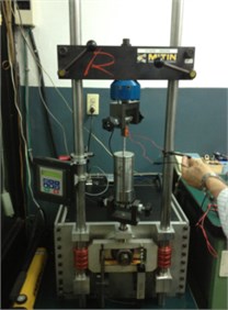
The new MR damper (Fig. 14) was tested on the damping test machine with input current ranged from 0 A to 2 A with 0.2 A increment (Fig. 15). The voltage is maintained at 12 V while the total electric resistant of the damper is around 2 Ω.
Fig. 14Manufactured 4-pole MR damper
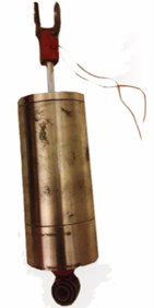
Fig. 15Experiment apparatus for test of MR damper
3.3. Results and discussions
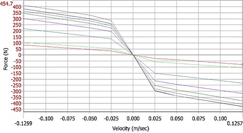
The experimental results of the new MR damper are plotted in F-D and F-V charts as seen in Figs. 16 and 17. With the change of input current, it is obvious that the damping force from the damper varies with that change. The higher the velocity is, the larger the damping force is. It confirms that the new MR damper provides significantly extended operation range and a good adaptive controllability via input current.
The damping force of MR damper, applied current and piston speed can be observed in Fig. 8. In the F-D chart in Fig. 16, when the piston block begins to move from the equilibrium point, its damping force tends to drop significantly no matter compression or tension force. When the MR damper moves, since the resistance pressure is too low, the reverse pressure provided by bottom gas chamber is deficient.
Generally, 10 kg pressure is added into gas chamber from the outer of MR damper after MR fluid is pour into the damper. Air pressure always exists in the this small space. However, gas chamber merely employs two rubber baloons to serve as buffer for this MR damper. When piston block moves, gas chamber cannot offer moderate pressure to influence damping force.
Compared with compression force and tensile strength, the compression force is usually smaller than tensile strength for dampers. However, results show that compression force is greater than tensile strength in this experiment. From this point, the deficiency of pressure in gas chamber plays an important role. When piston block moves toward tensile direction, gas chamber has not give rebound pressure.
In this study, the test was performed at two low speeds (0.03 m/sec and 0.05 m/sec) and one medium speed (0.13 m/sec). If the applied current increases from 0 A to 1.6 A, the compression force becomes 7.66 times higher for test speed at 0.03 m/sec, and 5.1 times higher for speed 0.05 m/sec, and 2.56 times higher at medium speed 0.13 m/sec. These test results indicate that the MR damper can have variable damping, and the range of damping force is significantly extended.
Fig. 16F-D chart for MR damper with multiple poles
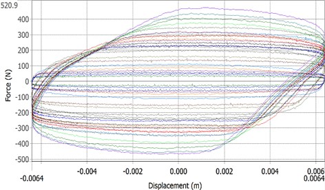
Fig. 17F-V chart for multiple-pole MR damper
4. Conclusions
In this study the new concept of MR damper with multiple poles is proposed. Several parameters as well as the cost function were figured out in the optimization. Optimal design of the new MR damper was found via magnetic simulation. This design was manufactured and tested.
Test results of the multi-pole MR damper support the fact that the change of applied current significantly affects the damping force. Increasing the applied current from 0 A to 1.6 A will obtain 766 % enhancement of compression force at 0.03 m/sec, or 256 % enhancement at 0.13 m/sec. The experimental results confirm the feasible of the operation concept and availability of highly controllable damping force. It can be later applied to semi-active suspension system.
References
-
Tao R. Super-strong magnetorheological fluids. Journal of Physics: Condensed Matter, Vol. 13, 2001, p. 979-999.
-
Dai S., Du C., Yu G. Design, testing and analysis of a novel composite magnetorheological fluid clutch. Journal of Intelligent Material Systems and Structures, Vol. 24, Issue 14, 2013, p. 1675-1682.
-
Lee D.-Y., Choi Y.-T., Wereley N. M. Performance analysis of ER/MR impact damper systems using Herschel-Bulkley model. Journal of Intelligent Material Systems and Structures, Vol. 13, Issues 7-8, 2002, p. 525-531.
-
Urreta H., Leicht Z., Sanchez A., Agirre A., Kuzhir P., Magnac G. Hydrodynamic bearing lubricated with magnetic fluids. Journal of Physics: Conference Series, Vol. 149, 2009, p. 012113.
-
Goncalves F. D. Characterizing the behavior of magnetorheological fluids at high velocities and high shear rates. Ph.D. Thesis, 2005.
-
De V. J., Klingenberg D. J., Roque H. A. Magnetorheological fluids: a review. Soft Matter, Vol. 7, Issue 8, 2011, p. 3701.
-
Choi S.-B., Nam M.-H., Lee B.-K. Vibration control of a MR seat damper for commercial vehicles. Journal of Intelligent Material Systems and Structures, Vol. 11, Issue 12, 2000, p. 936-944.
-
Shiao Y., Nguyen Q.-A. Development of a multi-pole magnetorheological brake. Smart Materials and Structures, Vol. 22, Issue 6, 2013, p. 065008.
-
Shiao Y., Huang Y.-K. Design of an innovative high-torque brake. Advanced Materials Research, Vol. 338, 2011, p. 622-625.
-
Choi K.-M., Jung H.-J., Lee H.-J., Cho S.-W. Feasibility study of an MR damper-based smart passive control system employing an electromagnetic induction device. Smart Materials and Structures, Vol. 16, Issue 6, 2007, p. 0036.
-
MRF-132DG Magneto-Rheological Fluid. Lord Corporation, 2013.
About this article

This study has been sponsored by the National Science Council – Taiwan (Project No. NSC 101-2221-E-027-033).
