Abstract
This research is concerned with the investigation of forced time-harmonic vertical vibration of a rigid disk enclosed in a transversely isotropic full space medium. By properties of integral transform methods, the generalized mixed boundary-value problem is formulated as a set of dual integral equations, which in turn, are reduced to a Fredholm equation of the second kind. The obtained Fredholm integral equation is solved by well-known numerical methods. Selected results for the load distribution on the disk and complex compliance are presented for various ranges of frequency periments.
1. Introduction
The interaction of a loaded disk with an elastic object is a subject of major interest in the field of applied mechanics, applied mathematics and civil engineering. As a classical example of soil-structure interaction problems in civil engineering, a static analysis of this kind is good in providing a fundamental understanding of the behavior of foundations under external loads and piers in soil. Its dynamic analog is vital to earthquake engineering, seismology, and machine vibrations. In the subject of solid mechanics, the foregoing class of problems is also related to the study of load transfers, fracture mechanics, stress concentrations, and nondestructive evaluation of inclusions and composites through the wave propagation method.
The first research of the elastostatic problem was a retry by Harding and Sneddon [1], who demonstrated how the technique of integral transforms can be employed to handle this set of boundary-value problems. It is worth indicating this subject that the corresponding problem for an isotropic solid for the instance where the disk in the shape of a penny was solved by Collins [2]. Later, Keer [3] has worked on the interaction of a thin rigid coverage embedded in an isotropic elastic solid of infinite content under prescribed displacements. Kassir and Sih [4] first considered the problem for the object where the disk has the shape of ellipse and since then, Green and Sneddon [5], employed elliptical coordinates and elliptical harmonics for the Laplace operator to find the solution of the problem. From the results of their problem, they can anticipate the critical failure load and the outset of crack propagation close to the edge of the disk in a method similar to that one which has been recommended by Panasyuk and Andreikiv [6], and after that extended by Rahman [7]. Other static solutions similarly have been obtained on the response of a rigid disk buried on the surface of a half-space, as in, Sneddon [8], Keer [9] and Spence [10]. Other problems related with a rigid disk embedded in an elastic half-space have also been investigated, as in Sneddon [11].
For the dynamic interaction between a rigid disk and an elastic medium, both methods, the half-space and full-space items, are also available as in Reissner and Sagoci [12], Arnold et al. [13], Gladwell [14] and Selvadurai [15]. A summary of the results on the axial, torsional, horizontal and rocking response of a half-space disk can be found in Luco and Westmann [16].
It has long been recognized that deformation behavior of many materials depends upon orientation; that is, the stress-strain response of a sample taken from the material in one direction would be different if the sample were taken in a different direction. The term anisotropic is generally used to describe such behaviors. Early investigators of these phenomena were motivated by the response of naturally occurring anisotropic materials such as wood and crystalline solids. Today, extensive use of engineered composites has brought forward many new types of fiber and particle-reinforced materials with an anisotropic response. Thus, knowledge of stress distributions in anisotropic materials is very important to properly use these new high-performance materials in structural applications. Nowadays anisotropic materials are of major concern because of their high performance in technological applications. Most innovative, smart, and intelligent materials such as composites, piezo-magnetics, and piezo-electrics are anisotropic. Moreover, the anisotropy effects are also important in the field of geotechnical engineering since the fabric of many natural soils and rocks displays anisotropic behavior. In practical applications, anisotropic solids are often transversely isotropic or orthotropic materials. The problems concerning the interaction of rigid disks in anisotropic materials have been studied to a lesser extent, mainly because of the more complicated nature of their constitutive behaviors.
Wang and Shi worked on finding the general solutions of transversely isotropic elasticity [17]. Afterwards Rahman [18] considered the static response of a transversely isotropic half-space with an embedded elliptical disk subjected to a normal shift moreover studied about bonded contact of a flexible elliptical disk with a transversely isotropic half-space [19]. Later, Yue et al. [20] introduced stresses and displacements of a transversely isotropic elastic half-space due to rectangular loadings. In the end Eskandari-Ghadi and Ardeshir-Behrestaghi [21] exposed forced vertical vibration of the rigid circular disk buried in an arbitrary depth of a transversely isotropic half-space.
Wave propagation in elastic medium induced by arbitrary internal sources is a subject of vital interest in mechanical engineering and civil engineering because of its fundamental importance in earthquake engineering, foundation vibration, dynamic structures and soil-structures interaction. The wave propagation in isotropic materials has been the subject of many researches. The first research dates back to the work of Lamb [22], who investigated the object of a surface vertical point or line time-harmonic force acting on an isotropic elastic half-space. Many researchers since then have proposed a variety of elastodynamic issue related to isotropic materials. Pak [23] worked on an isotropic half-space subjected to an arbitrary, time-harmonic, finite, buried source analytically. This work is extended by Pak and Guzina [24] for the determination of the Green’s functions for an isotropic layered half-space. Wave propagation in an anisotropic medium, has received less attention. On the other hand, the need to understand the wave propagation in an anisotropic media has risen substantially from the increasing need because of their high utility in technological applications. Most advanced innovative materials such as composites, magnetic and piezo-composites are anisotropic and in real application need to be modeled as transversely isotropic or orthotropic media.
One of the first treatments of the wave propagation on transversely isotropic materials dates back to the work of Michell [25], who solved the elastostatic problems of a transversely isotropic half-space elastic body under arbitrary prescribed surface tractions. Afterwards Wang and Achenbach [26], introduced a treatment to construct solutions for elastic waves in a half-space and solved Lamb’s problem for an anisotropic media based on superposition of time-transient plane waves. Eskandari-Ghadi [27], introduced a complete set of two displacement-potential functions to uncouple the equations of motion in transversely isotropic materials. By using these displacement-potentials, Rahimian et al. [28], designated an analytical formulation to obtain the response of a three-dimensional transversely isotropic, time-harmonic half-space. In the end, Khojasteh et al. [29] have introduced a new and efficient relation for asymmetric wave propagation in transversely isotropic half-space in displacement-potential that can be useful in a variety of elastodynamic problems.
In this paper, the problem of a rigid disk embedded in an elastic transversely isotropic full-space under forced vertical excitation is considered. By means of the time-harmonic Green’s functions for a transversely isotropic full-space introduced by Khojasteh et al. [29], the governing equations of the problem are reduced to a Fredholm integral equation. A set of complex vertical compliance functions with various applications in the dynamic soil-structure interaction is provided.
2. Equations of motion and potential functions
2.1. Equations of motion
The equations of motion for a homogeneous linear elastodynamic medium in the absence of body forces in terms of stress tensor in the cylindrical coordinate can be expressed as:
where, , and are the displacement components in the , and directions, respectively. Also, are Cauchy stress tensor in the cylindrical coordinate, is the mass density of the material and parameters is the time factor.
The stress-displacement relations in cylindrical coordinates can be found as follows:
Also:
where, and are Young’s module in the plane of transversely isotropy and in the direction normal to it, respectively. Also, and are Poisson’s ratios characterizing the lateral strain response in the plane of transverse isotropy to a stress acting parallel and normal to it, respectively. is the shear modulus in planes normal to the plane of transverse isotropy and denotes the shear modulus in the plane normal to the axis of symmetry. Then with substituting Eq. (2) into Eq. (1), the equations of time-harmonic motion for homogeneous transversely isotropic elastic solid in terms of displacements and in the absence of body forces can be rewritten as:
where, is the circular frequency.
2.2. Potential functions
The Eq. (4) is an uncouple equation with partial differential equations. Because of complicated solutions of these kinds of differential equations, using the method of potential functions plays an important role in solving complex boundary-value problems. To solve the Eq. (4), we use potential functions and . They are used in solving dynamic boundary-value problems in the transversely isotropic medium, which degenerates the Lekhnitskii-Hu-Nowacki solution in the static case and further to Muki’s formulation for isotropic materials. These two potential functions, and , are related to displacement components , and through the following relations:
where, is Laplacian. Substituting Eq. (5) into Eq. (4) results in two distinct partial differential equations (PDEs) as the governing equations for potential functions, and , can be obtained. By using the property of Fourier expansion with respect to angular coordinate , potential functions are given by:
In view of the boundary conditions of the problem and for solving partial differential equations, it is practical to using virtue of th-order Hankel integral transform with respect to the radial coordinate in the form of:
With its inversion formula:
where, is the Henkel’s parameter and denotes the th-order Bessel function of the first kind. Employing the Hankel integral transform leads to the following values of and [30]:
where:
Also, ,…, are constants of integration to be determined from boundary conditions. In addition, and are the roots of the following equation, which in view of the positive-definiteness of the strain energy are not zero or pure imaginary numbers:
In the case of the static problem, i.e. , for Kernel function in transversely isotropic full-space materials, the relation is valid [31].
3. Problem statement and governing integral equations
3.1. Statement of problem
For the considered problem, suppose an elastic full-space that has the transversely isotropic behavior. In this problem, there is a mass less rigid disk with radius that has been located in infinity, homogeneous, linear elastic solid (Fig. 1). Assume that the rigid disk tolerates the specified changes of time-harmonic vertical displacement , with being the amplitude of the motion. Also for modeling this kind of problem that is related to interaction between soil and rigid disk, it should be assumed that the disk is entirely rigid and has complete contact with surrounding medium.
In view of the axial symmetry of the problem, it is natural to adopt the cylindrical coordinate, , and the axis of symmetry of the medium is assumed to be normal to the horizontal disk. In a cylindrical coordinate system, where -axis is the axis of symmetry of the medium, therefore the angular component of the displacement field and the angular dependence of the solution can be vanished.
3.2. Boundary conditions
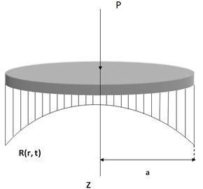
In terms of the components of the Cauchy stress tensor and the displacement vector , a relaxed treatment of the mixed boundary-value problem can be stated as follows:
where, is the unknown dynamic contact load distribution acting on the disk (Fig. 2).
Fig. 1Rigid disk in a transversely isotropic full-space medium
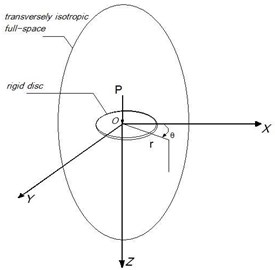
Fig. 2The unknown dynamic contact load distribution R(r,t)
3.3. Transformed displacement
In view of the geometry and boundary conditions of this problem in relations Eqs. (12) and (13), the displacement of rigid disk is considered in -direction. Therefore with applying nominative branch points in transversely isotropic materials and using potential functions in Eq. (5), and also observantly with identities of Hankel integral transform the general solution in Eq. (9) lead to the transformed displacement-potential relation in the form of [32]:
Substitution of the result into Eq. (14), white considering the theory of Hankel integral transforms, in the end the vertical component of the displacement field under the action of the arbitrary force field on the plane, it can be shown as [32]:
Then, from Eq. (8), the vertical component of the displacement field is:
where, and denotes the Bessel function of the first kind of order . Also, is Kernel function for transversely isotropic full-space materials, is defined by [32]:
Considering of the locality of rigid disk in leads to:
where:
The two Boundary conditions Eqs. (12) and (13) of the mixed boundary-value problem are equivalent [32]:
This is a pair of dual integral equations.
4. Reduction and solution of dual integral equations
Now as a solution to solve the dual integral equations, Eq. (20), we applied the particular method of setting the limit on Kernel function, , with the set up of the known coefficients and replacing them in , leads to:
Furthermore, the relation Eq. (21), can be used for isotropic materials when relations:
are valid. This leads to the following equation:
The method of governing dual integral equations is facilitated by first converting them into an alternative form. Following Nobel [33], it can be shown, with the aid of Sonine’s integrals that Eq. (20) can be derived as:
where:
In addition to more reduction of dual integral equations, it is advantageous to define a function of the form [33]:
With its inversion formula as follows:
A general Fredholm equation of the second kind is written as:
Given the Kernel and the function , the problem is to find the function . By properties of relations Eq. (27), it can be shown that the pair of dual integral Eqs. (24), conduced to Fredholm integral equation of the second kind:
where:
5. Numerical analysis
For numerical intents, the governing Fredholm integral Eq. (29), can be resolved to a set of linear algebraic equations through the following equations:
where:
Also:
In the preceding equations, stands for the Kernel function of the governing equation, is an assemblage of nodal locations on the rigid disk and indicates the Kronecker delta. After that with properties of the definitions of the Kernel function and by considering the Eq. (25), the Eq. (34) is expressed as:
Because of the presence of radical functions, Bessel functions and exponential, in a complex form of Eq. (35), the integrals can not be carried out in exact closed forms. A numerical analysis usually has to be adopted in such evaluations. With the aid of the numerical method, the procedure adopted in this research involves locating the branch points associated with branch cuts that render all functions single valued. First of all, for more simplicity, assume that the radius of rigid disk , is one and should divide the rigid disk into equal divisions. It is clear that when these nodal locations are more and more the results of the problem are better than before therefore the rigid disk is divided into 100 pieces. It needs to be pointed out that all numerical results presented here are dimensionless with a non-dimensional frequency defined as [29]:
With the previous assumption for the radius of rigid disk , the non-dimensional frequency can be written as:
There are several reasons for carrying out numerical integration and numerical derivation. The integrand function may be known only at certain points. Some embedded systems and other computer applications may need numerical integration for this reason. There are several popular numerical computing applications and computer algebra systems such as Mathematica that benefit from the availability of the arbitrary precision arithmetic which can provide more accurate results. Therefore, for this complicated problem, an adaptive numerical approach is adopted and coded in Mathematica 7, software.
6. Results
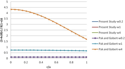
To provide a verified program review technique and precision of results, dynamic solution in isotropic materials that were presented by Pak and Gobert [32] has compared with present study. The isotropic valid relations are as:
The comparison of results of the numerical integration for dynamic solution and dynamic compliance on the complex-plane has been defined in Figs. 3 and 4. As indicated in the figures, there are excellent agreements between the two solutions.
Fig. 3Comparison of the dynamic solution (real part)
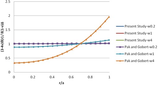
Fig. 4Comparison of the dynamic solution (imaginary part)
6.1. Dynamic solution
In order to determine the algebraic Eq. (32) and gain the matrix , it is essential to solve Eq. (35), in the form of numerical integration. For this purpose, by applying in different ranges of circular frequency , of the motion, it has been hypothesized that this problem of a transversely isotropic full-space made by Beryl Rock material. Its elastic coefficients are listed in Table 1.
Table 1Beryl rock material engineering constants (elastic constants; GPa)
41.3 | 14.7 | 10.1 | 36.2 | 10 | 13.3 |
Table 2Properties of synthetic materials
Material 1 | 30 | 11.2 | 10.3 | 55.1 | 10 | 0.33 | 2 |
Material 2 | 26.5 | 5.2 | 7.9 | 79 | 10 | 0.17 | 3 |
Material 3 | 27.2 | 7.2 | 8.6 | 129.3 | 10 | 0.25 | 5 |
The illustration of the dynamic solution of this transversely isotropic material is prepared in Figs. 5 and 6.
To demonstrate the influence of the degree of the material anisotropy and the type of loading on the response, a parametric study is conducted. Several synthetic types of transversely isotropic materials are considered to constitute basic materials. The materials properties are given in Table 2, where and are the Young’s modules with respect to directions lying in the plane of isotropy and perpendicular to it and is Poisson ratio which characterizes the effects of horizontal strain on complementary horizontal strain [28]. In defining these materials, the positive definiteness of strain energy that observes the following constraints for materials constants have been checked.
Fig. 5Dynamic solution θ for beryl rock material (real part)
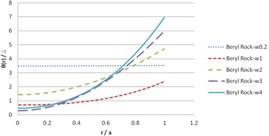
Fig. 6Dynamic solution θ for beryl rock material (imaginary part)
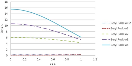
Fig. 7Dynamic solution θ for synthetic material 1 (real part)
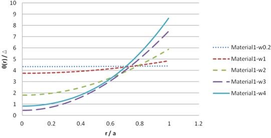
Fig. 8Dynamic solution θ for synthetic material 1 (imaginary part)
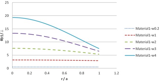
Fig. 9Dynamic solution θ for synthetic material 2 (real part)
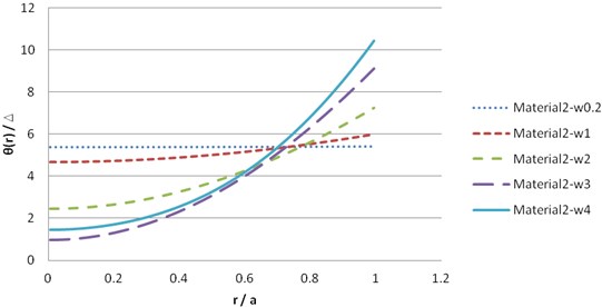
Fig. 10Dynamic solution θ for synthetic material 2 (imaginary part)
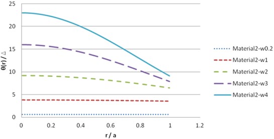
Fig. 11Dynamic solution θ for synthetic material 3 (real part)
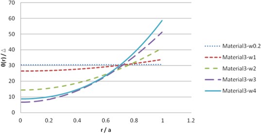
Fig. 12Dynamic solution θ for synthetic material 3 (imaginary part)
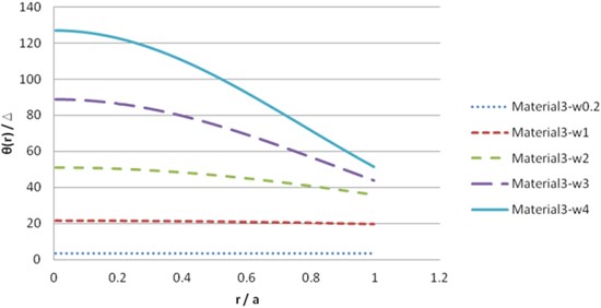
The illustration of the dynamic solution of synthetic transversely isotropic materials is shown in Figs. 7-12.
6.2. Load-displacement relations
The total vertical load required to achieve the displacement can be obtained by integrating the net normal contact load pressure over the rigid disk as follows [32]:
It can be shown that the unknown contact load distribution acting on the rigid disk can be obtained by including numerical integration and numerical derivation, as follows:
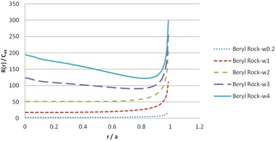
To solve the contact load , we should dissolve the numerical derivation. The simplest method is to use finite difference approximations. The numerical result of Eq. (40), for beryl rock and synthetic materials leads to the following results in Figs. 13-20.
Fig. 13Contact load pressure R(r) for beryl rock (real part)
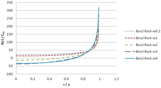
Fig. 14Contact load pressure R(r) for beryl rock (imaginary part)
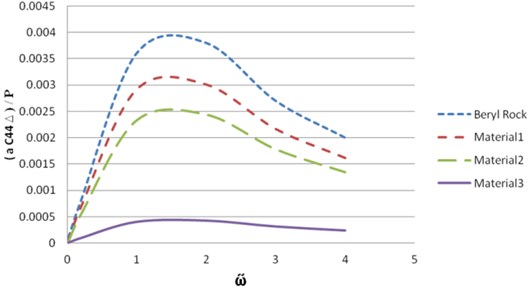
6.3. Dynamic compliance
In addition, with the view of achieving dynamic compliance for the rigid disk, on substituting Eqs. (40) into (39), and performing the integration, one fields that the resultant load is expressible as [32]:
This can be evaluated directly in terms of the solution of the Fredholm equation. With the solution given by , one may express the dynamic compliance, which is the ratio of to . The results of the dynamic compliance for beryl rock and synthetic transversely isotropic materials take the following results shown in Figs. 21 and 22.
Fig. 15Contact load pressure R(r) for material 1 (real part)
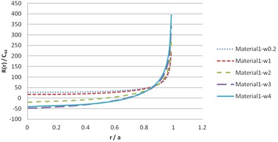
Fig. 16Contact load pressure R(r) for material 1 (imaginary part)
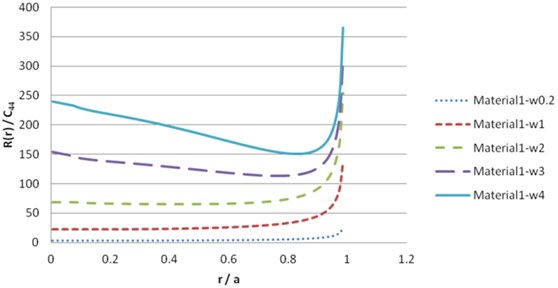
Fig. 17Contact load pressure R(r) for material 2 (real part)
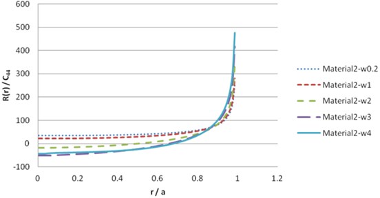
Fig. 18Contact load pressure R(r) for material 2 (imaginary part)
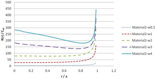
Fig. 19Contact load pressure R(r) for material 3 (real part)
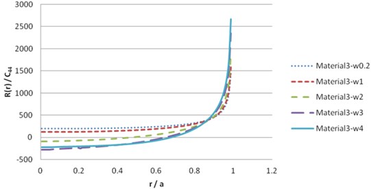
Fig. 20Contact load pressure R(r) for material 3 (imaginary part)
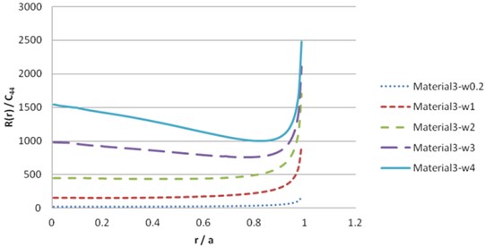
Fig. 21Comparison of results for dynamic compliance (real part)
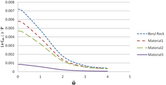
Fig. 22Comparison of results for dynamic compliance (imaginary part)
7. Conclusions
In this paper, the response of an elastic transversely isotropic full-space to an arbitrary, time-harmonic, buried source is derived using the method of displacement potentials and integral transforms. Some numerical results for the contact pressure and compliance factor corresponding to the beryl rock full-space are also presented.
References
-
Harding J. W., Sneddon I. N. The elastic stresses produced by the indentation of the plane surface of a semi-infinite elastic solid by a rigid punch. Mathematical Proceedings of the Cambridge Philosophical Society, Vol. 41, Issue 1, 1945, p. 16-26.
-
Collins W. D. Some axially symmetric stress distributions in elastic solids containing penny-shaped cracks, cracks in an infinite solids and a thick plate. Proceeding of the Royal Society of London, Vol. 266, Issue 1326, 1962, p. 359-386.
-
Keer L. M. A note on the solution of two asymmetric boundary value problems. International Journal of Solids Structure, Vol. 1, Issue 3, 1965, p. 257-264.
-
Kassir M. K., Sih G. C. Some three-dimensional inclusion problems in elasticity. International Journal of Solids Structure, Vol. 4, Issue 2, 1968, p. 225-241.
-
Green A. E., Sneddon I. N. The distribution of stress in the neighborhood of a flat elliptical crack in an elastic solid. Proceedings of the Cambridge Philosophical Society, Vol. 46, Issue 1, 1949, p. 159-163.
-
Panasyuk V. V., Andreikiv A. E. On the problem concerning the failure of a brittle body with a disc-shaped circular crack. International Applied Mechanics, Vol. 3, 1967, p. 20-23.
-
Rahman M. Bonded contact of a flexible elliptical disk with a transversely isotropic half-space. International Journal of Solids and Structures, Vol. 36, Issue 13, 1999, p. 1965-1983.
-
Sneddon I. N. The Reissner-Sagoci problem. Proceedings of the Glasgow Mathematics Associate, Vol. 7, Issue 3, 1966, p. 136-144.
-
Keer L. M. Mixed boundary value problems for an elastic half-space. Proceedings of the Cambridge Philosophical Society, Vol. 63, Issue 4, 1967, p. 1379-1386.
-
Spence D. A. Self-similar solutions to adhesive contact problems with incremental loading. Proceedings of the Royal Society of London, Vol. 305, Issue 1480, 1968, p. 55-80.
-
Sneddon I. N. Fourier Transforms. McGraw-Hill, New York, 1951.
-
Reissner E., Sagoci H. F. Forced torsional oscillations of an elastic half-space. Journal of Applied Physics, Vol. 15, Issue 9, 1944, p. 652-654.
-
Arnold R. N., Bycroft G. N., Warburton G. B. Forced vibrations of a body on an infinite elastic solid. Journal of Applied Mechanics, ASME, Vol. 22, 1955, p. 391-400.
-
Gladwell G. M. L. Forced tangential and rotatory vibration of a rigid circular disc on a semi-infinite solid. International Journal of Engineering Science, Vol. 6, Issue 10, 1968, p. 591-607.
-
Selvadurai A. P. S. Rotary oscillations of a rigid disc inclusion embedded in an isotropic elastic infinite space. International Journal of Solids and Structures, Vol. 17, Issue 5, 1981, p. 492-498.
-
Luco J. E., Westmann R. A. Dynamic response of circular footing. Journal of Engineering Mechanics, ASCE, Vol. 95, Issue 5, 1971, p. 1381-1194.
-
Wang W., Shi M. X. On the general solutions of transversely isotropic elasticity. International Journal of Solids Structures, Vol. 35, Issue 25, 1997, p. 3283-3297.
-
Rahman M. The normal shift of a rigid elliptical disk in a transversely isotropic solid. International Journal of Solids and Structures, Vol. 38, Issue 22-23, 1999, p. 3965-3977.
-
Rahman M. Bonded contact of a flexible elliptical disk with a transversely isotropic half-space. International Journal of Solids and Structure, Vol. 36, Issue 13, 1998, p. 1965-1983.
-
Yue Z. Q., Xiao H. T., Tham L. G., Lee C. F., Yin J. H. Stresses and displacements of a transversely isotropic elastic half-space due to rectangular loadings. Engineering Analysis with Boundary Elements, Vol. 29, Issue 6, 2005, p. 647-671.
-
Eskandari-Ghadi M., Ardeshir-Behrestaghi A. Forced vertical vibration of rigid circular disk buried in an arbitrary depth of a transversely isotropic half-space. Soil Dynamic and Earthquake Engineering, Vol. 30, Issue 7, 2010, p. 547-560.
-
Lamb H. On the propagation tremors over the surface of an elastic solid. Philosophical Transactions of the Royal Society, Vol. 203, Issue 359-371, 1904, p. 1-42.
-
Pak R. Y. S. Asymmetric wave propagation in an elastic half-space by a method of potentials. ASME Journal of Applied Mechanics, Vol. 54, Issue 1, 1987, p. 121-126.
-
Pak R. Y. S., Guzina B. B. Three-dimensional green’s functions for a multilayered half-space in displacement potentials. Journal of Engineering Mechanics, ASCE, Vol. 128, Issue 4, 2002, p. 449-461.
-
Michell J. H. The stress in an aeolotropic elastic solid with an infinite plane boundary. Proceedings of the London Mathematical Society, Vol. 32, 1900, p. 247-258.
-
Wang C. Y., Achenbach J. D. Lamb’s problem for solids of general anisotropy. Wave Motion, Vol. 24, Issue 3, 1996, p. 227-242.
-
Eskandari-Ghadi M. A complete solution of the wave equations for transversely isotropic media. Journal of Elasticity, Vol. 81, Issue 1, 2005, p. 1-19.
-
Rahimian M., Eskandari-Ghadi M., Pak R. Y. S., Khojasteh A. Elastodynamic potential method for transversely isotropic solid. Journal of Engineering Mechanics, ASCE, Vol. 133, Issue 10, 2007, p. 1134-1145.
-
Khojasteh A., Rahimian M., Eskandari M., Pak R. Y. S. Asymmetric wave propagation in a transversely isotropic half-space in displacement potentials. International Journal of Engineering Science, Vol. 46, Issue 7, 2008, p. 690-710.
-
Lekhnitskii S. G. Theory of Elasticity of an Anisotropic Elastic Body. Holden Day, San Francisco, 1963, p. 121-128.
-
Stoneley R. The seismological implications of aeolotropy in continental structures. Royal Astronomical Society Monthly Notices, Geophysical Supplement, London, England, Vol. 5, 1949, p. 343-353.
-
Pak R. Y. S., Gobert A. T. Forced Vertical Vibration of Rigid Disc with Arbitrary Embedment. International Journal of Engineering Mechanics, Vol. 117, Issue 11, 1991, p. 2527-2548.
-
Nobel B. The solution of Bessel function dual integral equations by a multiplying-factor method. Proceedings of the Cambridge Philosophical Society, Vol. 59, Issue 2, 1963, p. 351-362.
About this article

