Abstract
A novel pendulum type of vibration isolation module is proposed in this paper which consists of passive and active layers. The active layer is consisted of a hollow ring-type piezoelectric actuator embedded in the vibration module, and an accelerometer is located on the payload disc to perform closed loop control. The passive layer is formed by an elastomer pad inserted between the active layer and payload disc for high frequency isolation. The equations of motion in the vertical and horizontal directions are derived using the Lagrangian approach. The transmissibility function is measured and used for setting performance specifications. The uncertainties due to the payload variations are included in generating the plant template. Then the controller based on the quantitative feedback theory is designed to achieve robustness as the payload of the plant varies from 40 to 60 Kg. Experiments are conducted to validate the performances the isolation module for both vertical and horizontal directions. The pendulum structure could reduce the first natural frequency in the horizontal direction to be about 1.875 Hz such that high frequency disturbance rejection can be achieved. Experimental results also demonstrate that the active control could reduce vibrations by more than 10 dB within the frequency range from 20-35 Hz and 20 dB at the first resonance. The time domain signals measured from the ground and payload with control on and off verify the performances of the vibration isolation system.
1. Introduction
In the field of micro and nano manipulation, for examples, biological manipulation [1, 2] and scanning probe microscopy [3], quiet platforms are required to achieve micro or nanometer positioning accuracy positioning. Other devices such as coordinate measuring machines (CMM), interferometers, atomic force microscopes (AFM) and etc. could be affected by external ground disturbance [3]. In the above equipment, micro-scale vibration isolations are essential and active vibration control strategies are frequently used. To perform active controls, piezoelectric materials are one of the most popular actuators which have the advantages of high stiffness, high resolution, and broad bandwidth. The high force density also enables the actuators to be suitable for miniaturization [4]. The use of piezoelectric actuators for active vibration systems have widely used in linear stages [5-8], in which different types of feedback signals such as acceleration, velocity, position, and integral forces are applied [9].
Many semi-active, active and active-passive vibration isolation systems have been proposed [10]. The control methodologies such as classical control [11, 12], optimal linear-quadratic-Gaussian (LQG) control [13], and neural networks [14] were proposed in the past. However, the above control algorithms did not address the issues of system uncertainty such as parameter variation, and payload changes. To ensure vibration isolation system could be applied for different types of equipment, system robustness should be considered. To achieve robustness, two control methodologies were proposed. One is the adaptive control [15] and the other is quantitative feedback theory (QFT) [16, 17]. Karande et al. [18] analyzed the performance of a QFT based controller in attenuating vibrations for the flexible multilink robotic manipulator systems. Zapateiro et al. [19] designed the QFT based controller to reduce vibration for a 6-story building structure equipped with shear-mode magnetorheological (MR) dampers. They also applied the QFT controller to the suspensions of vehicles using the MR damper [20]. Tsai et al. designed a QFT controller for a pendulum vibration isolation system with consideration of payload uncertainties and hysteresis effects of piezoelectric actuators [21]. Three piezoelectric actuators are embedded in three cables to support the center mass. Because the characteristics of three actuators are the same, the yawing motion of the isolation module could be excited even the identical voltages are applied to the three actuators
In this paper, a novel pendulum type of vibration isolation module is developed in that a single ring-typed piezoelectric actuator is located between intermediate mass and lower mass. The single actuator can control vertical vibrations without exciting other modes as compared to the previous design [21]. To analyze the system behavior, dynamic equations of motion are derived in both horizontal and vertical directions. Experiments are conducted to validate system dynamics. Then the QFT controller is designed for the system with consideration of payload uncertainty. Ground transmissibility is utilized for determining the specification of control design. Validity of the isolation mechanism and QFT controller is confirmed by closed-loop frequency and time domain responses with the payloads varying from 40-60 Kg.
2. Equations of motion in vertical and horizontal directions
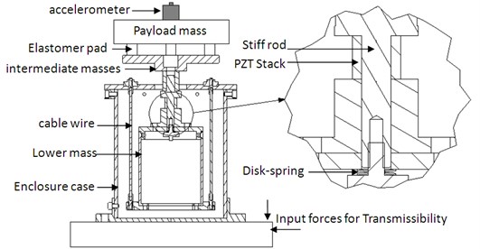
The design of the novel pendulum-type vibration isolation module is shown in Fig. 1. The enclosure case is connected to the lower mass by three cable wires to form the pendulum system. One side of the stiff rod is screwed on the center mass and the other side of the rod is attached to the lower mass with a preload disk-type spring. A hollow ring-type piezoelectric actuator is located between the lower and intermediate masses. The elastomer pad is inserted between the payload disc and the intermediate mass to form a passive layer. On top of the payload, an accelerometer is installed for sensing feedback. As the vibrations are sensed by the accelerometer, the signal is sent to the controller to actuate the piezoelectric actuators to perform closed loop control which is targeted for low frequency vibration reductions. Control of high-frequency vibrations are damped with the passive layer. In the horizontal direction, only passive action is applied. The pendulum mechanism and elastic layer are designed for low frequency and high frequency vibrations, respectively. The first resonance frequency in the horizontal direction is determined by the length of the cable wires.
The dynamics of the isolation module in the vertical direction can be represented by a three degree-of-freedom (dof) lumped spring-damper-mass model shown in Fig. 2. The generalized coordinates , and represent the displacements of the payload, actuator and lower mass, respectively. The stiffness and damping of the cables in the vertical direction are represented by and , respectively. and represent the equivalent stiffness and damping which include the preload effects, the ring type actuator as shown in Fig. 2. is the combination mass from the lower and center masses. The stiffness and damping of the elastomer pads are denoted as and , respectively.
Fig. 1Vibration isolation module and its sectional view
By applying Lagrangian formulation, the dynamic model of the isolation system in the vertical direction can be expressed as follow:
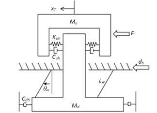
In the horizontal direction, the developed system provides passive isolation effects by utilizing the pendulum-type structure to obtain the low first natural frequency. The vibration could be attenuated significantly when the frequency of ground disturbance excitation is above the first natural frequency. Furthermore, the elastomer layer provides damping to high frequency modes. To derive the equation of motion in the horizontal direction, a simplified lumped mass-damper-spring model as shown in Fig. 3 is adopted. Here and represent the payload and lower/center masses, respectively. is assumed to undergo a small and non-rotational motion. In addition, is the disturbance displacement in the horizontal direction, is the corresponding displacement of the upper mass in the horizontal direction, and is the angle of the piezoelectric cables with respect to the vertical direction. and are the stiffness and damping of the elastomer layer in the horizontal direction, respectively. is the damping of the pendulum. By applying the Lagrange equation, the dynamic model of the isolation system in the horizontal direction can be expressed as:
Fig. 2Dynamic model of vibration isolation module in the vertical direction
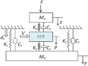
Fig. 3Dynamic model of vibration isolation module in the horizontal direction
3. Experimental validation of dynamic model
In this section, experiments are conducted to analyze the dynamic characteristics of vibration isolation module. In order to determine the specifications of control design, the transmissibility of the sensor signal from ground to that of the payload mass is measured. The sensors (PCB393M52, sensitivity 1 V/g) are installed on the ground and the payload disc in the same direction (horizontal or vertical), respectively. The excitation from impact hammer (PCB 086C20, sensitivity 0.23 mV/N) was applied on the mounting platform shown in Fig. 1. Then the signals were measured by dynamic signal analyzer (HP 35670A) to obtain the frequency response of the transmissibility between the acceleration of the ground and that of the payload.
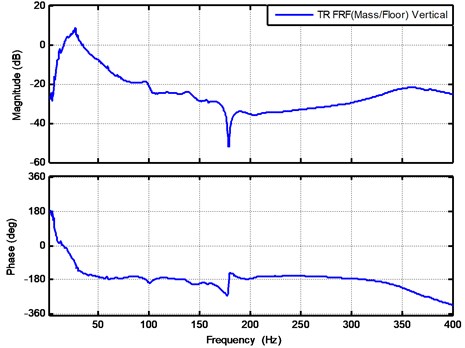
The experimental result of the transmissibility in the vertical direction is shown in Fig. 4. Two resonances were observed in the frequency response function. By following the similar analysis based on the previous studies [23], the natural frequency of the first resonance is about 30 Hz which is approximately equal to . Here is the stiffness of the elastomer layer and is the upper mass. The second natural frequency is about 360 Hz which is approximately equal to . The second mode is related to the stiffness of wire cable , that of piezoelectric actuator , and intermediate mass . It can be seen from Fig. 4 that the magnitudes for the frequency range from 15 Hz to 35 Hz is higher than 0 dB which indicate the vibrations within these range are amplified and active controls should be applied to these ranges to reduce the transmissibility to be below 0 dB. The experimental results will be used for determining the specification for active controls.
Fig. 4The transmissibility for floor to payload mass in vertical direction
To further investigate the transmissibility in the horizontal direction, the frequency response is shown in Fig. 5. It is shown that the first resonance is related to the swing frequency of pendulum which is about 1.875 Hz. The second natural frequency is about 11 Hz which is related to the shear motion between the payload, center and lower masses. The system identification process is performed by following the approach in [23] and all of the system parameters are listed in Table 1 unless stated otherwise.
Fig. 5The transmissibility testing result for floor to payload mass in horizontal direction
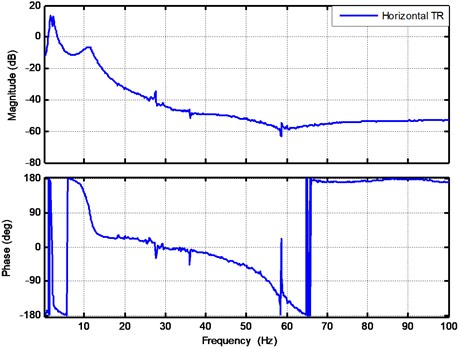
Table 1Parameters used for vibration isolation module
Symbol | Value | Unit |
50 | Kg | |
2.54 | Kg | |
0.18 | N/m | |
0.024 | N/m | |
1.32 | N/m | |
0.0047 | N/m | |
1200 | N∙sec/m | |
300 | N∙sec/m | |
700 | N∙sec/m | |
700 | N∙sec/m | |
90 | N∙sec/m | |
0.17 | m |
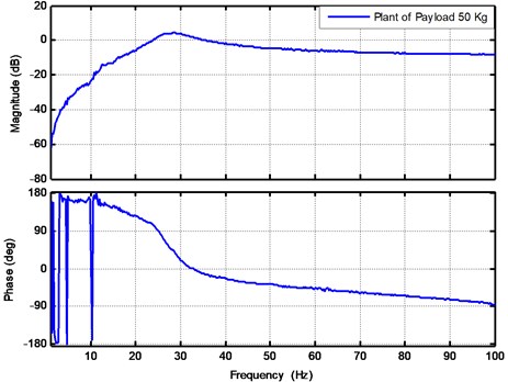
To perform active controls, the open loop frequency response function between the accelerometer and actuator is measured first. To include payload uncertainty, the nominal plant is chosen to be 50 Kg. A chirp sine signal is applied to the piezoelectric actuator and the output signal obtained from the accelerometer is again processed using the dynamic signal analyzer HP35670A. The experimental results for the frequency response function between the applied voltage and the acceleration output signal in the vertical direction are presented by Fig. 6. The excitation voltage is chosen as 1.0 V chirp sine signals respectively, which were generated from the dynamic signal analyzer HP35670A and then were amplified 30 times to drive the piezoelectric actuator. The output voltage corresponding to the acceleration in the vertical direction is measured by the accelerometer with the sensitivity equal to 1 V/g. Here g is equal to 9.81 m/s2. The unit of the figure is given as V/V in dB. As shown in Fig. 6, the natural frequency was about 29 Hz which is close to the first resonance shown in Fig. 4. Finally, the nominal plant of load 50 Kg is chosen for controller design.
Fig. 6Open loop plant in the vertical direction with payload mass equal to 50 Kg
4. QFT control design of vibration isolation module
Control of the vibration isolation system can be regarded as the disturbance rejection problem shown in Fig. 7. The plant is the open loop system with payload uncertainties, and is the controller. is plant-output disturbance, is the error, is controller output, and is system output. The nominal plant is denoted as and the nominal loop transmission, , is shown in Nichols chart to satisfy stability and disturbance bounds.
In design active controller for the vibration isolation module, the quantitative feedback theory (QFT) is utilized to consider the plant with system uncertainties [24]. In order to evaluate the uncertainties, the frequency response functions under the payload equal to 40 Kg and 60 Kg are shown in Fig. 8.
Fig. 7Control block diagram for disturbance rejection
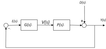
Fig. 8Testing results of sweep-sine test of plants for vertical direction of vibration isolation module when payloads equal to 40 Kg, 50 Kg and 60 Kg
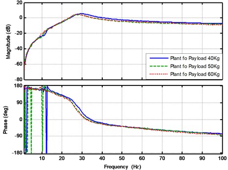
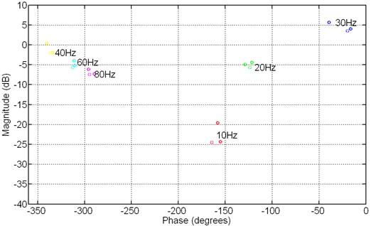
During the control design process, plant uncertainties due to payload variations shown in Fig. 8, can be used to build the plant templates at specific frequencies to indicate the magnitude and phase changes for the payload variation. The frequencies points of 10 Hz, 20 Hz, 30 Hz, 40 Hz, 60 Hz, 80 Hz are chosen for building the plant templates and shown in Fig. 9. Both magnitude and phase changes are obvious near the resonance frequency of and the vertical and horizontal of elastomers pad. The other frequency points show that the uncertainties due to payload variations are small.
After building the plant templates, the specified gain and phase margins should be sufficient to accommodate all plants represented by the nominal plant and uncertainty model to ensure a robust performance. To guarantee the stability bound with a sufficient phase margin, the loop transmission (denoted as ) must not enter the U-contour in the Nichols chart at any of the given frequencies [24]. Here, the U-contour in Fig. 10 is defined as:
where is equal to . The gain and phase margins are related to as follows [25]:
Fig. 9Plant templates for vibration isolation module
As indicated by the transmissibility shown in Fig. 4, the control authority should be focused around the first natural frequency. Therefore, the first U-contour bound is to let the crossover frequency is be higher than 45 Hz, and the phase margin at the crossover frequency to be at least higher than 15 degree. The value of is calculated to be 3.83 from Eq. (4). The second U-contour bound is chosen to let the phase of the larger than –150 degree within the frequency ranges of 10 to 40 Hz and the corresponding is computed as 1.93. The egg-shaped U-contour bounds at different frequencies are shown in Fig. 10 where the uncertainties are included in generated the bounds.
Fig. 10Robustness bounds and disturbance rejection bounds for QFT design
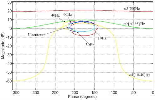
Besides of the stability bounds, the performance bounds set the specifications for the disturbance rejection. It is shown in Fig. 4 that the passive layer could provide isolation effects when the frequency is higher than 40 Hz. However, the amplification due to the first resonance causes the transmissibility higher than 0 dB within the frequency range from 10-40 Hz. By taking the transmissibility into consideration, the performance bound for the disturbance rejection is specified as follows:
Here the disturbance rejection criteria by Eq. (7) ensure that the maximum resonance peak can be reduced by –20 dB with the QFT controller. The performance bounds specified by , and in Eq. (5)-(7) are shown in Fig. 10.
Once the QFT bounds have been specified, the loop-shaping process is performed to design the controller. The controller is given as the following:
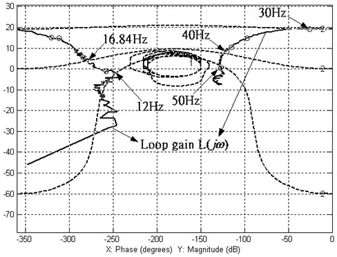
The resulting loop gain with the design QFT controller is shown in the Nichols chart of Fig. 11. It is clear that the loop gain does not enter the U-contour at any of the specified frequencies, and thus the robustness of the control performance is ensured. In addition, it is seen that the magnitude of at each frequency is higher than the corresponding disturbance bounds specified by , and .
Fig. 11The Nichols chart of the loop gain with the QFT controller
5. Experimental results and discussion for implementing QFT controller
After designing the QFT controller, the closed loop experiments were conducted. The experimental results for the plant, open loop and closed loop frequency responses under the payload load equal to 50 Kg are shown in Fig. 12. By comparing the open and closed loop frequency responses, it is shown that the active control is effective from 10 Hz to 45 Hz. The maximum vibration reduction at the first resonance is about 20 dB which agree with the disturbance bound when designing the QFT controller.
In order to evaluate the robustness of the designed controller for payload variation, the open loop and closed loop experiments were conducted with the payloads equal to 40 Kg and 60 Kg and the results are shown in Fig. 13 and Fig. 14, respectively. It is clear that the system robustness are ensured and the performance requirement are achieved even under the payload variations.
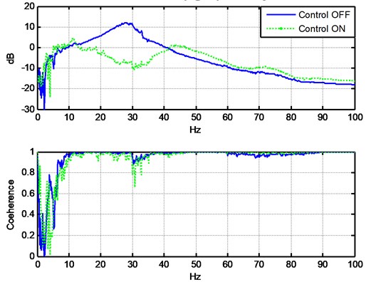
Fig. 15 shows the transmissibility function for the nominal plant. When the active control is activated, the transmissibility is below 0 dB for the frequency below 40 Hz. However, there is a slightly spillover when the frequency is higher than 60 Hz. Over 10 dB vibration reduction can be achieved within the frequency range from 20-35 Hz. The experiments are also conducted for the payload equal to 40 Kg and 60 Kg. The control performances under different payloads are very similar to that of the nominal plant which shows the robustness of the controller.
Fig. 12The experimental results for the plant, open loop and closed loop frequency response functions at payload mass 50 Kg
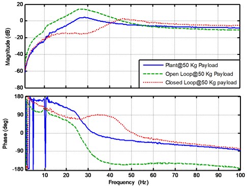
Fig. 13The experimental results for the plant, open loop and closed loop frequency response functions at payload mass 40 Kg
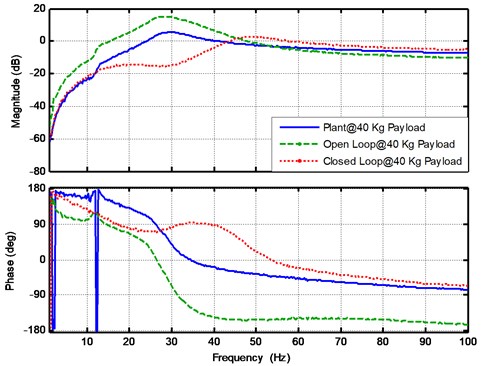
Fig. 14The experimental results for the plant, open loop and closed loop frequency response functions at payload mass 60 Kg
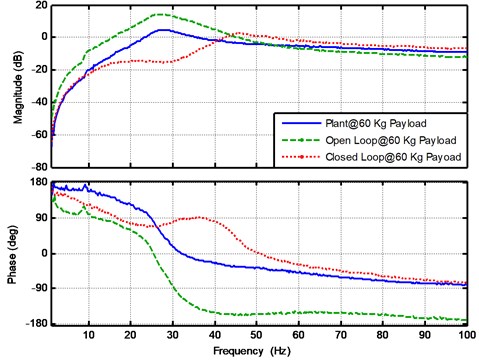
Fig. 15The transmissibility for the payload 50 Kg when the control modes are on and off
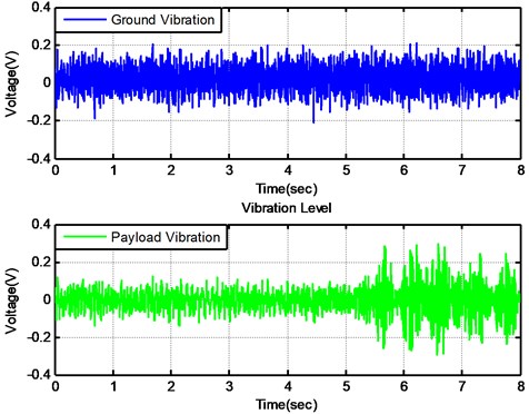
The vibration isolation system can be further evaluated by comparing the time domain responses measured from the floor and payload when the active control is set on and off. Fig. 16 shows the time domain signals when active control is turned on at the beginning and off after 5 seconds. It is clear that the root mean square value of vibrations under the active control could reduce the level by more than 50 % which demonstrate the effectiveness of the vibration isolation module. It is also observed that the vibration level at the payload is almost the same as that at the floor when the active control is off. It is probably due to the first resonance peak as shown in Fig. 4.
Fig. 16The time domain signals of both floor and payload mass when active control is on and off
6. Conclusions
In this paper, a novel active-passive vibration isolation module has been developed. A hollow ring-type piezoelectric actuator is installed in the isolation module to perform active control and the elastomer pad is inserted between the payload disc and intermediate mass to form the passive layer. The transmissibility function from the ground to the payload is measured and used for control design specifications. The equations of motion in the vertical and horizontal directions are derived using the Lagrangian approach and validated by experimental results. It is shown that the first natural frequency can be designed to be about 1.875 Hz under the pendulum structure. To account for the payload uncertainty, the QFT theory is applied for the controller design. The plants under different payloads are tested and the plant templates are built. Then the stability and performance bounds are chosen based on the uncertainties and transmissibility function and the QFT controller is obtained. The experimental results show that the active control can reduce the vibration over 10 dB within the frequency range from 20-35 Hz and the maximum 20 dB vibration attenuation can be achieved at the first resonance. Furthermore, the comparisons of the time domain signal measured from the ground and payload validate the performances of the vibration isolation system.
References
-
Zhang Y., Tan K. K., Huang S. Vision-servo system for automated cell injection. IEEE Transactions on Industrial Electronics, Vol. 56, Issue 1, 2009, p. 231-238.
-
Ramadan A. A., Takubo T., Mae Y., Oohara K., Arai T. Developmental process of a chopstick-like hybrid-structure two-fingered micromanipulator hand for 3-D manipulation of microscopic objects. IEEE Transactions on Industrial Electronics, Vol. 56, Issue 4, 2009, p. 1121-1135.
-
Bonnail N., Tonneau D., Jandard F., Capolino G.-A., Dallaporta H. Variable structure control of a piezoelectric actuator for a scanning tunneling microscope. IEEE Transactions on Industrial Electronics, Vol. 51, Issue 2, 2004, p. 354-363.
-
Fleming A. J., Moheimani R. Sensorless vibration suppression and scan compensation for piezoelectric tube nanopositioners. IEEE Transactions on Control Systems Technology, Vol. 14, Issue 1, 2006, p. 33-44.
-
Holterman J., de Vries T. J. A. Active damping within an advanced microlithography system using piezoelectric smart discs. Mechatronics, Vol. 14, Issue 1, 2004, p. 15-34.
-
Holterman J., de Vries T. J. A. Active damping based on decoupled collocated control. IEEE/ASME Transactions on Mechatronics, Vol. 10, Issue 2, 2005, p. 135-145.
-
Hanieh A. A., Preumont A. Frequency variation for the purpose of vibration isolation. IEEE International Conference on Mechatronics, 2006, p. 176-180.
-
Rodriguez-Fortun J. M., Orus J., Alfonso J., Gimeno Francisco Buil, Castellanos Jose A. Flatness-based active vibration control for piezoelectric actuators. IEEE/ASME Transactions on Mechatronics, Vol. 99, 2011, p. 1-9.
-
Preumont A. Vibration Control of Active Structures, 2nd ed. Kluwer, Norwell, MA, 2002.
-
Anderson E. H., Houghton B. ELITE-3 active vibration isolation workstation. Proceedings of Smart Structures and Materials 2001: Industrial and Commercial Applications of Smart Structures Technologies, Vol. 4332, 2001.
-
Beard A. M., Schuber D. W., von Flotow A. H. A practical product implementation of an active/passive vibration isolation system. Active Control of Vibration and Noise, 1994, p. 485-492.
-
Hyde T. T. An experimental study of active vibration isolation. AIAA Structures, Structural Dynamics and Materials Conference Proceedings, Vol. 2, 1997, p. 1763-1773.
-
Sievers L. A., von Flotow A. H. Comparison of two LQG-based methods for disturbance rejection. Proceedings of the 28th Conference on Decision and Control, 1989, p. 483-485.
-
Ahn E. G., Pahk H. J. A hybrid-type active vibration isolation system using neural networks. Journal of Sound and Vibration, Vol. 192, 1996, p. 793-805.
-
Anderson E. H., How J. P. Active vibration isolation using adaptive feedforward control. Proceedings of the American Control Conference, 1997, p. 1783-1788.
-
Choi S. B., Cho S. S., Jeon Y. S. Vibration and tracking control of piezoceramic-based smart structures via quantitative feedback theory. Proceedings of Smart Structures and Materials 1997: Mathematics and Control in Smart Structures, Vol. 596, 1997.
-
Comasòlivas R., Escobet T., Quevedo J. Automatic loop shaping of QFT applied to an active control design. 19th Mediterranean Conference on Control and Automation, 2011.
-
Karande S., Nataraj P. S. V., Gandhi P. S., Deshpande M. M. Control of parallel flexible five bar manipulator using QFT. IEEE International Conference on Industrial Technology, 2009, p. 1-6.
-
Zapateiro M., Luo N., Karimi H. R. QFT control for vibration reduction in structures equipped with MR dampers. American Control Conference, Seattle, Washington, USA, 2008.
-
Zapateiro M., Pozo F., Karimi H. R., Luo N. Semiactive control methodologies for suspension control with magnetorheological dampers. IEEE/ASME Transactions on Mechatronics, 2011, p. 1-11.
-
Tsai M. S., Chiang F. C., Sun Y. S., Wu J. H. Robust QFT control of a piezo-based vibration isolation system with consideration of hysteresis effect. ASME 7th Biennial Conference on Engineering Systems Design and Analysis, 2004, p. 717-723.
-
IEEE Standard on Piezoelectricity. ANSI-IEEE Std. 176-1987, 1987.
-
Tsai M. S., Sun Y. S., Liu C. H. Robust control of novel pendulum-type vibration isolation system. Journal of Sound and Vibration, Vol. 330, Issues 18-19, 2011, p. 4384-4398.
-
Yaniv O. Quantitative Feedback Design of Linear and Nonlinear Control Systems. Kluwer Academic Publishers, 1999.
-
Doyle J. C., Francis B. A., Tannenbaum A. R. Feedback Control Theory. Maxwell Macmillan, 1992.
About this article

