Abstract
An efficient method to reduce the frequency averaged transverse vibration level of a plate by optimizing the position of attached passive constrained layer damping PCLD is presented. This method uses a multilayer anisotropic plate model which is an equivalent single layer plate model (ESL) where transverse shear stresses and displacements are continuous at each layer’s interfaces. Hence, for a laminate composed of an arbitrary number of layers, all the quantities are related to those of the first layer. The optimization process is based on the use of the ESL plate model combined with the genetic algorithm (GA) and Latin Hypercube Sampling (LHS) algorithm implemented in a Rayleigh-Ritz resolution program. The convergence acceleration of the method is achieved thanks to the combination of genetic algorithm and the use of the ESL plate model instead of a three-dimensional mesh that requires more computing resource.
1. Introduction
Numerous solutions have been developed in the past to reduce the vibration level of vibrating structures. Two main approaches were usually used: passive methods based on a good knowledge of damping mechanisms to increase energy dissipation and active control methods using electrical devices such as controllers and sensors to reduce the overall level of vibration. Passive treatments, generally, remain appreciated in transportation domain, in particular in aeronautic field where mass reduction is appreciated.
Nowadays, passive constrained layer damping (PCLD) is a classical method for reducing vibrations in vehicles. This is achieved by covering totally or partially vibrating surfaces using patches of viscoelastic materials in order to reduce vibrations and sound radiation arising from local deformation of structures. The technical principle is that of a high loss factor viscoelastic layer attached to the base structure and constrained on its other side by a metallic layer. According to Rao [1], this layer thus acts as a kinematic amplifier to increase significantly the shear deformations in the layer. Thus, when the base structure vibrates in bending, the viscoelastic layer will be subjected to a large shear deformation resulting in conversion of kinetic energy into heat.
As regards experimental study of patches based on visco-constrained material, Kerwin [2] was among the first to propose a study of a patched beam for which he establishes the structural loss factor, based on the work of Oberst. Other experimental studies have been proposed on different structures like beam or plate as that of Kumar and Singh [3] who propose a study on a curved panel. In general, many experimental studies have been conducted on visco constrained patches.
Given an existing structure, the optimization of the treatment process of structures by passive patches consists to predict where to add PCLD patches in order to get the most possible reduction in terms of vibration energy of the system, with a limited quantity of added viscoelastic material.
The two dominant approaches used to solve this optimization problems are the Gradient based approach and the Evolutionary Approach such as genetic algorithms.
The Gradient based approach is simple but may converge to local minima which do not always give optimal solutions. Liu and Wang [4] have studied the integration of enhanced active constrained layer and active-passive hybrid constrained layer treatments using a mixed method where a method called Differential Evolution (DE) for continuous function optimization is combined with the Gradient based method. Zheng et al. [5] have studied the optimal extent and placement of PCLD on beams. Chen and Huang [6] have studied the optimal placement of CLD treatment of plates.
Evolutionary approaches are preferred because they do not converge to a local minimum as the case of conventional methods in which the final solution depends on the choice of the initial solution. Among these approaches, genetic algorithms (GA) have been widely used by researchers in the field of structural optimization, especially composite materials. In addition, these methods do not require derivative nor linearity of the objective function and constraints, to orient the search to the optimal solution [7].
As regards the objective function to be optimized, some authors prefer to optimise the modal loss factor over a frequency range [8-10] others have chosen to minimize the modal energy [11]. In this study, the chosen objective function to minimise is the averaged quadratic velocity.
Since the characteristics of the structure change in a major way in the transverse direction, because of the added patches, most methods use Layer-Wise Formulation to describe the vibration behaviour of multilayer plates. In this case, displacement fields are expressed for each layer. Hence, during the discretization of the system, the number of degrees of freedom of the system is directly dependent on the number of layers. Although it may be more accurate, this formulation often involves a large number of degrees of freedom, which makes it cumbersome to use in a finite element discretization, specially in an optimization process where the calculation of the objective function is needed multiple times.
The proposed study uses an Equivalent Single Layer (ESL) formulation which describes each component of the displacement field of each layer depending on variables defined in a reference plane. Therefore, displacements of the different layers are described by the and coordinates of the reference plane and the normal direction to the plane , .
The optimization process is based on the GA and the ESL model, since the number of added patches do not increase the final number of variables describing vibrational behaviour of the overall structure.
Rayleigh-Ritz method was preferred to a classical finite element discretization as it avoids imposing a compulsory compatible mesh with the shape of patches to be placed on the base structure.
The chosen objective function is the transverse mean square velocity (MSV) averaged over the surface and integrated over a frequency range. Obviously, this indicator does not permit to see the distribution of energy over the structure, but it has the benefit of involving the active and reactive energy of the plate.
2. Model
2.1. Viscoelastic model
The Zener model also known as a standard viscoelastic model is used to describe the dynamic behaviour of the viscoelastic material. This model has been proved to be efficient in describing the dynamic behaviour of materials, especially polymers used for sound and vibration. This model is obtained from the stress-strain visco elastic relationships used to describe the time behaviour of the material. For harmonic analysis, the linear viscoelastic behaviour of materials is then written with complex quantities and frequency dependent variables:
The symbol indicates that the variable is complex and is the complex, frequency dependent Young’s modulus. can be written as follows:
The real part and imaginary part represent, respectively, the elastic and viscous behavior of the material. The material loss factor can be written in function of real and imaginary parts of Young’s modulus:
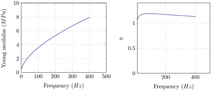
Polymers often exhibit a strong frequency and temperature dependence for their Young’s modulus and loss factor, as shown in many previous works like [5]. Generally, Young’s modulus increases with frequency, and the loss factor shows a peak along the frequency axis.
2.2. Multilayer plate model
As mentioned earlier, the ESL formulation allows one to simulate the behaviour of a rectangular multi-layered plate with one or several multi-layered patches. It is based on an out-of-plane assumed displacement field obtained by means of kinematic considerations. This approach was used in the early work of Sun and Whitney [12] for multi-layered plates and has been used later for vibroacoustical purposes by Guyader and Lesueur [13].
It is a two-dimensional plate model with the five classical displacement unknowns, but it differs from classical laminate theories (CLT) and the (first-order) shear deformation theory (SDT) because the assumed displacement variation, with respect to , is piecewise linear. This is the result of writing continuities of both displacements and shear stresses at the interface, as shown below in Fig. 1. For practical reasons, the displacement field of each layer is linked to the displacement field of the first layer. Thicknesses and elevations for an n layer material are presented in Fig. 1. The displacement field in each layer is written as follows:
where Greek indices stand for in-plane quantities and take values 1 or 2, superscript stands for the th layer and superscript 1 stands for the first layer for which all will be related, are the transverse (engineering) shear strains, and is the elevation of the layer .
Fig. 1Geometrical parameters of the multilayer structure (represented on the left side in an undeformed state) and displacements (represented on the right side after deformation)
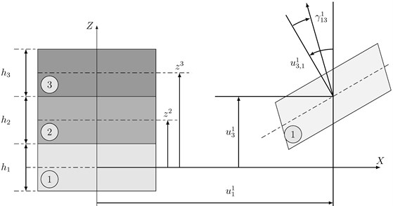
With these assumptions, the transverse displacement and the transverse shear strains are constant within each layer with respect to the -coordinate. Therefore, transverse shear stresses will also be constant in each layer. According to these remarks, the conditions that are enforced reduce to:
• The continuity of displacements:
• The continuity of transverse shear stresses:
Eqs. (5) and (6) allow linking the displacements field in the th layer with the one of the th layer, and, recursively, it can be linked to the displacement field of the first layer, following a process detailed in Ref. [13]. As the first layer is common to the uncovered and covered parts of the plate, all the displacements in the multilayered structure are known in terms of the first layer’s displacement field, including only the five classical plate unknowns: three displacements and two rotations The construction of the discrete motion equation system is achieved by the Rayleigh-Ritz method.
3. Optimisation method
3.1. Generic properties of the used method
The optimisation method is performed through an iterative process. For a given surface and a given coverage rate , the optimisation objective is to provide the best arrangement of patches in order to reduce vibration level over a given frequency range using an optimization algorithm:
where is the surface to be covered with patches and is the total surface of the base plate. For each step or generation during the optimization process, simulations are performed using different patch arrangements called samples or populations, each sample being identified by a set of geometrical parameters to define position and surface of patches over the base plate:
being the surface of patch which is an element of sample . To evaluate the efficiency of each sample, MSV is averaged over the surface of the plate and integrated over the frequency range :
Each iteration is called a generation. The algorithm tries to propose new samples becoming part of a new generation in order to improve the criteria. The sample issued from this optimization process is taken as the solution of the optimisation problem. To obtain this solution, two techniques are combined, Latin Hypercube Sampling (LHS) and genetic algorithm (GA).
The first technique is a random sampling method proposed by McKay et al. [14] as an alternative of simple random sampling in computer experiments, while the second one is a stochastic optimization method based on mechanism of natural evolution and genetic theory. LHS generates a hypercube which is a working space for the involved variables, and proposes samples belonging to this hypercube. The main benefit of the LHS algorithm, compared to random sampling, is that the working space is efficiently sampled with a reduced number of samples. In the present method, the LHS algorithm provides the set of initial samples and also gives new samples which are added to complete the generations at each iteration.
At the same time, GA searches the best approximated solution of a complex problem using different operators based on biological evolution theory. So, GA manipulates a family of solutions and implements a simulated evolution (survival of the fittest) strategy in the search for better solutions. In general, the fittest individuals of any population tend to reproduce and survive to the next generation, thus improving successive generations. GA is chosen because it has been shown to solve linear and non-linear problems by exploiting all regions of the state space. This prevents the convergence to a local minimum.
In this work, GA is implemented using crossover and mutation operators. The best samples are chosen using the objective criteria presented above. Samples are crossed to create new samples which contain information on the last ones, in order to obtain better candidates.
3.1.1. Used method
3.1.1.1. Initial sample and election
The initial set samples is given by the LHS method. In order to define the limits of the LHS hypercube, variation ranges of the position of patches are proposed. These limits are set as of the probable value of each variable. The required response is computed for each sample and the MSV is computed to choose the best parent samples using the appropriate selection criterion. The next steps propose new samples trying to improve the criteria.
3.1.1.2. Evolution
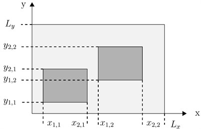
The solution is searched using a GA with binary encoding. The best samples are crossed by a GA crossover operator producing samples named “children”. To illustrate the crossover and mutation processes, one considers the optimization example of the position of two patches defined by their coordinates see Fig. 4. Each element of the vector is called gene. Suppose one wants to cross the two solutions defined by:
One begins by generating a random binary vector . Suppose this vector is:
The crossing process of these two solutions gives two children:
After ranking all children obtained by crossing, one keeps only the best children.
To allow a permanent renewal of the population, mutation of some genes with a predefined mutation rate is performed. In the previous example, the total number of genes after crossing process is . If the mutation rate is , then genes will be selected randomly and will be changed.
Better solutions can be lost using crossover operator since it only recombines past information which may lead to the predominance of cloned samples. Considering this, the LHS proposes new samples to the next generation, to study others possible trends of the method. Then, the new generation consists of the union of , and samples. A new simulation is done with them to compare the new response, and so forth. It is important to note that the number of samples issued from LHS and GA are chosen to have successive generations with a constant number of samples. The choice of the best sample is carried out by the presented criteria.
3.1.1.3. Stop criteria
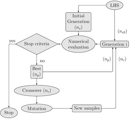
The iterative method is stopped when both, correlation and area have the achieved values or when the maximum number of iteration is reached. The flow diagram of the optimization process is shown in Fig. 2.
Fig. 2Flowchart for the optimisation algorithm
3.2. Used algorithms
The mechanical structure used for this study consists of a plate on which one must place one or more patches to have a maximum reduction of vibration. Plate dimensions are specified in Fig. 3.
3.2.1. Mono-patch optimization
This part concerns positioning of a single patch on the base plate. Surface of the patch to be placed is fixed beforehand, so, each sample consists of four variables called also genes which are the four coordinates , , and of the patch relative to the base plate.
To generate the initial population, the LHS method is applied on the variable which varies between 0 and to benefit from the symmetric geometry. Then, for each sample, one seeks the minimum value of which corresponds to the position giving a strip with a width , a maximum height and a surface defined by the prefixed coverage rate where is the surface of the patch and the surface of the base plate. The final value of is randomly chosen between the minimum limit and the maximum limit . To obtain the ordinate and , the width required for the fixed coverage rate is used. Then value of the variable is chosen randomly between 0 and . Finally, is obtained by the equation: .
Then, efficiency calculation of samples, their ranking, parent choice, crossover and mutation are obtained in a conventional manner.
Samples to be crossed by a GA crossover operator are chosen by the classical roulette-wheel. For a couple , , crossover permutations are performed only on genes 2 and 3. To allow the evolution of gene 1, mutation is performed only on . As explained previously, the fourth gene is not a variable, but is deduced from the other parameters. A verification step is performed to ensure that obtained samples by crossover and mutation process satisfy the coverage rate and belonging to the base plate conditions.
Fig. 3Patch positioning
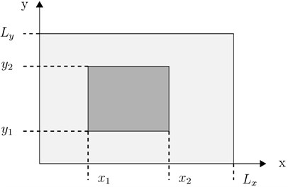
Fig. 4Patch positioning
3.2.2. Multi-patch optimization
Positioning problem of multiple patches on the base plate, without overlap, introduces several variables, making more complex the optimization. The main difference with the mono-patch problem is the distribution of the covered surface on several patches without overlapping. For a given sample, the total area to be covered is shared randomly on all patches constituting the sample. For this, surfaces , , ,… have been assigned to different patches 1, 2,… ().
Two chromosomes matrices are thus defined. The first matrix contains data relating to surfaces while the second matrix contains position data of each patch. So, sample is defined as:
The rest of the process is identical to the mono-patch case. For each iteration, one checks that the generated samples consist of non-overlapping patches, and completely included in the base plate. Note that this method becomes complex when the number of patches is important.
3.2.3. Multi-band optimization
According to the previous study concerning the multi-patches optimization, it is noted that the number of variables increases rapidly with the number of patches to be placed, making the optimization method difficult to implement. In this section, considered patches are strips with the same width in order to reduce the number of variables.
Thus the total surface of the base plate is divided into N strips with the same width. A binary vector consisting of 0 or 1 is generated to specify the presence or absence of viscoelastic patch on each strips. The total area of the patches is randomly distributed over all strips which should be covered by patches . In this case, optimization variables are:
• Components of a vector to specify existence or absence of a patch over the strip.
• Distribution of surfaces to be covered on the strips.
• Patch positions over the strips
Thus, three matrixes are used for optimization variables. The first matrix is used to identify the bands with or without a patch, the second to specify the covered surface of each strip and the last to define the positions of patch over covered strip. The rest of the algorithm is the same as the previous.
Fig. 5Patch positioning
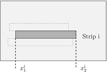
Fig. 6Positon of the excitation force
4. Numerical simulation
4.1. Tested example
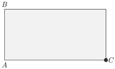
The used structure consists of an aluminium plate, length 0.5 m, width 0.4 m. The four edges of the plate are free. A unit harmonic force is applied at the point A ( 0.5, 0.0) as shown on Fig. 6. The excitation frequency range is 10-40 Hz which include the frequency of the first and second bending mode.
Patches to be placed consist of a viscoelastic material and an aluminium constrained plate. Thickness and material characteristics are specified in Table 1.
Young modulus and loss factor of the viscoelastic material are shown on Fig. 7.
The first three mode shapes as well as their associated eigen-frequencies are given on Fig. 8.
Table 1Properties of materials of base beam and PCLD patch
Properties | Base plate | Constraining material | Viscoelastic material |
Young modulus, (GPa) | 70 | 70 | – |
Loss factor, (%) | 0.1 | 0.1 | – |
Density, (kg/m3) | 2700 | 2700 | 1000 |
Poisson ration, | 0.3 | 0.3 | 0.45 |
Thickness (mm) | 1.5 | 0.5 | 0.2 |
Fig. 7Variation curve of Young modulus and of loss factor of the viscoelastic material versus frequency
The objective function is the MSV averaged over the surface of the plate and integrated over the excitation frequency band. The coverage rate is 40. The problem was solved with the proposed method using Rayleigh-Ritz instead of the finite element method. Therefore, the form of patches and their numbers are completely independent of the resolution method.
Fig. 8Mode shapes of the bare plate
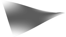
a) Mode shape 1, 24.69 Hz
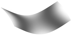
b) Mode shape 2, 32.24 Hz

c) Mode shape 2, 51.46 Hz
4.2. Results
Quantity, number and shape of patches to be placed on the base plate depend on the chosen optimization algorithm. Mono-patch algorithm works with a single patch, the multi-pach was used with 3 patches and finally the multi-band is applied with a division of 10 strips along the horizontal direction of the plate.
Patches coordinates provided by the optimization process are shown on Table 2.
Table 2Patches coordinates relative to the base plate
Patch | (mm) | (mm) | (mm) | (mm) | |
Mono-patch | 1 | 40 | 290 | 80 | 400 |
Multi-patch | 1 | 20 | 310 | 190 | 300 |
2 | 20 | 320 | 110 | 180 | |
3 | 20 | 280 | 300 | 400 | |
Multi-band | 1 | 30 | 430 | 80 | 120 |
2 | 30 | 450 | 120 | 160 | |
3 | 60 | 480 | 160 | 200 | |
4 | 10 | 370 | 200 | 240 | |
5 | 20 | 430 | 240 | 280 |
Fig. 9Multi-band solution
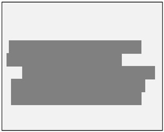
Fig. 10Objective function decrease according to the number of iterations
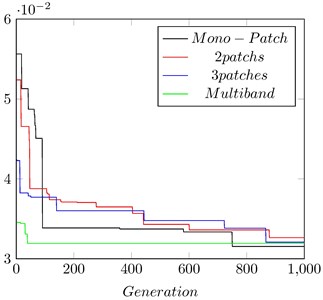
Fig. 9 is a graphic representation of the arrangement strips supplied from the multi-band optimization algorithm.
Elements of Table 3 show that the algorithms converge toward different solutions but values of the final objective function are roughly identical.
Table 3Reduction rate obtained by the three algorithms
Function objective (m2/s2) | Reduction | |
Mono-patch | 1.635 | 95.94 |
Multi-patch | 1.604 | 96.02 |
Multi-band | 1.136 | 97.18 |
5. Conclusions
Fig. 10 shows the evolution of the objective function for 1000 iterations performed by three optimization algorithms. It can be seen that the best solution is obtained with Algorithm 2, after it is followed by the algorithm 4 and 3, respectively
An optimization method of PCLD patches positions, based on genetic algorithms is presented in this study. This method uses an equivalent single layer (ESL) model, which a well-adapted model to optimization problems requiring significant computing time.
Thus a single-patch algorithm that places a single patch to reduce the vibration level in a given frequency bandwidth was developed. This algorithm has been extended to the case of two or more patches. The increased complexity of such algorithms with the number of patches to be placed led us to develop an algorithm that optimizes the position of patches that have the form of strips with a constant width.
The different algorithms have generally converged towards different solutions, but with substantially the same objective functions. All these solutions tends to place PCLD treatment on the structure nodal lines, for a given mode shape, i.e. on the areas of high strain energy.
References
-
Rao M. D. Recent applications of viscoelastic damping for noise control in automobiles and commercial airplanes. Journal of Sound and Vibration, Vol. 262, 2003, p. 457-474.
-
Jr Edward, Kerwin M. Damping of flexural waves by a constrained viscoelastic layer. The Journal of the Acoustical Society of America, Vol. 31, Issue 7, 1959, p. 952-962.
-
Kumar Navin, Singh S. P. Experimental study on vibration and damping of curved panel treated with constrained viscoelastic layer. Composite Structures, Vol. 92, Issue 2, 2010, p. 233-243.
-
Liu Y., Wang K. W. Damping optimization by integrating enhanced active constrained layer and active-passive hybrid constrained layer treatments. Journal of Sound and Vibration, Vol. 255, 2002, p. 763-775.
-
Zheng H., Cai C., Tan X. M. Optimization of partial constrained layer damping treatment for vibrational energy minimization of vibrating beams. Journal of Mechanical Sciences, Vol. 44, 2002, p. 1801-1821.
-
Chen Y., Huang S. An optimal placement of CLD treatment for vibration suppression of plates. Journal of Mechanical Sciences, Vol. 44, 2002, p. 1801-1821.
-
Hau L. C., Fung E. H. K. Multi-objective optimization of an active constrained layer damping treatment for shape control of flexible beams. Smart Materials and Structures, Vol. 13, 2004, p. 896-906.
-
Grgoire Lepoittevin, Gerald Kress Optimization of segmented constrained layer damping with mathematical programming using strain energy analysis and modal data. Materials and Design, Vol. 31, 2010, p. 14-24.
-
Yi-Cheng Chen, Shyh-Chin Huang An optimal placement of CLD treatment for vibration suppression of plates. International Journal of Mechanical Sciences, 44, p. 20021801-1821.
-
Zheng H., Tan X. M., Cai C. Damping analysis of beams covered with multiple PCLD patches. International Journal of Mechanical Sciences, Vol. 48, Issue 12, 2006, p. 1371-1383.
-
Kumar Navin, Singh S. P. Vibration and damping characteristics of beams with active constrained layer treatments under parametric variations. Material and Design, Vol. 30, 2009, p. 4162-4174.
-
Sun C. T., Whitney J. M. Theories for the dynamic response of laminated plates. American Institute of Aeronautics and Astronautics Journal, Vol. 11, 1973, p. 178-183.
-
Guyader J. L., Lesueur C. Acoustic transmission through orthotropic multilayered plates, part i: plate vibration modes. Journal of Sound and Vibration, Vol. 97, 1978, p. 51-68.
-
Mckay M. D., Conover W. J., Beckman R. J. A comparison of three methods for selecting values of input variables in the analysis of output from a computer code. Technometrics, Vol. 21, 1979, p. 239-245.
