Abstract
Finite element modeling and active vibration control of a high-speed spinning flexible coupled electromechanical beam is investigated using a first-order approximation coupling (FOAC) model. Due to centrifugal forces caused by eccentricity in a spinning flexible beam, there exists coupling between axial and transverse vibration modes. The partial differential equations of motion of the beam governing this coupling are derived using Hamilton’s principle based on an FOAC model, and a finite element method for discretization is given. It is observed that the zero-order approximate coupling (ZOAC) model is valid for dynamic description of the flexible beam spinning at low speeds, but no longer valid at high speeds. However, the validity of FOAC model is confirmed at different speeds. Piezoelectric elements for active vibration control of the spinning flexible beam are analyzed and a velocity feedback controller is proposed. Simulation results demonstrate good performance of the proposed velocity feedback controller.
1. Introduction
Spinning beams play an important role in many branches of engineering, for instance, shafts of combustion engines, DC and AC motors, turbine blades, propellers, spindles of gyro-scopes for control of satellites and satellite booms. Accurate prediction of the dynamics of such structures is critical for accurate design and analysis of the modern engineering systems, manufacturing accuracy and machine efficiency. Free as well as forced vibrations of beams with an orientation in or perpendicular to the axis of rotation have been investigated since the earliest days of artificial satellites. For example, the spin orientation of Explorer I was changed due to the energy dissipation of the flexible antennas [1]. However, an accurate analysis of a flexible beam spinning at high speeds is not available as yet.
An appropriate beam theory and an accurate model are important for precise prediction of motion of such spinning beams [2]. Early researches on the spinning beam were based on the classical beam, or Euler-Bernoulli beam description. Dimentberg [3] was among the first to investigate the dynamics of pinned-pinned spinning Euler-Bernoulli beams. Bauchau and Eidel [4] studied the dynamic response and stability analysis of spinning beams undergoing large amplitude and rotations using the finite-element method in time and discussed the classical nonlinear beam problems.
It is generally known that, for a non-spinning isotropic beam, however, rotary inertia and transverse shear deformation have about the same order of influence on the dynamic predictions [5, 6]. Due to the introduction of gyroscopic, Coriolis and centrifugal effects in a spinning beam, inertia becomes more important. Therefore, it is essential to use the Rayleigh beam theory in study of the dynamics of spinning beams [7, 8].
Sheu and Yang [9] studied the critical speed, whirl speed and mode shape of a spinning beam using a Rayleigh beam model with rotatory inertia and gyroscopic effects. Qian et al. [10] investigated the non-contact dynamic testing of a highly flexible spinning vertical shaft and time frequency analysis through a camera-based 3D motion analysis system and the Hilbert-Huang Transform (HHT), respectively. Frank et al. [2] derived linear and nonlinear models of spinning Rayleigh beams and investigated dynamic characteristics of downward vertical spinning Rayleigh beams, respectively.
Besides, some researchers adopted Timoshenko beam theory to describe spinning beams. Such as Boukhalfa [11], who analyzed the free vibrations of the spinning composite shafts using the hp-version of the finite element method. Lee et al. [12] studied a spectral element model for the spinning Timoshenko shaft. Mustapha and Zhong [13] analyzed the free vibration of a circular doubly-symmetric spinning micro beam embedded in an elastic medium using a mathematical model and premised the formulation based on the higher-order modified couple stress theory. Chan and Wang [14] investigated the revolving superposed standing waves in a spinning Timoshenko beam, and showed that the revolving waves should be represented by wave functions in a form of four-component column matrix vectors.
In general, a spinning flexible beam usually results in large nonlinearity and large deflections, especially at high speeds which becomes necessary to investigate. Khadem and Shahgholi [15] studied the two-mode combination resonances of a simply supported rotating shaft undergoing large deflections, rotary inertia and gyroscopic effects. Shahgholi et al. [16] studied simultaneous primary resonances of a simply supported nonlinear spinning beam due to unbalance periodic force and parametric resonances arising from excitations due to unequal mass moments of inertia and flexural rigidities in the direction of the principal axes. Shahgholi et al. [17] investigated parametric and main resonances of an asymmetrical spinning beam with in-extensional nonlinearity and large deflections.
The traditional hybrid coordinate model of flexible system is considered as a zero-order approximate dynamic model as it neglects high order coupling deformation kinematics. All of the existing studies ignored the effects of rigid-flexible coupling of the spinning beam. While this may not be an important influencing factor at low spinning speeds, it may lead to erroneous results in some high speed cases. Therefore, it is important to include the effects of rigid-flexible coupling.
In this paper, the effects of rigid-flexible coupling are considered by using a FOAC model to describe the dynamic behavior of the spinning Rayleigh beam. A new formulation of Hamilton’s principle and a finite element method for the case of a spinning flexible beam are proposed. In addition, active vibration control of a high-speed spinning flexible mechanical-electric coupled beam is investigated using velocity feedback control strategy. Numerical simulations are also carried out to verify the validity of FOAC model and the effectiveness of the velocity feedback controller. The comparison of the displacement responses derived from the ZOAC model and the proposed model not only illustrates the deficiency of the ZOAC model, but also validates the proposed model.
This paper is organized as follows: Section 2 first presents the expression of FOAC model for a high-speed spinning flexible beam and the coupled governing partial differential equations of motion of the beam which is subjected to a three-directional force using Hamilton’s principle. Finite element modeling of the above-mentioned beam is given in Section 3, followed by the active vibration control implementation in Section 4. Section 5 provides numerical simulation and comparison studies using FOAC model and ZOAC model, and control simulations by the proposed controller. Finally, concluding remarks are given in Section 6.
2. Mathematical modeling
2.1. First-order approximation model
Consider a spinning square Rayleigh beam with rotatory inertia and gyroscopic effects, as shown in Fig. 1. It is spinning with constant angular velocity about its longitudinal axis, the length is , and the density is with a prescribed compressive axial load at both ends. Assuming the displacement of a point on the beam , the actual displacement along its longitudinal axis based on continuum medium mechanics [18] can be written as:
where:
Fig. 1A uniform pinned-pinned axially loaded spinning square Rayleigh beam

The integral term in Eq. (2) reflects axial shortening resulting from the transverse deformation. The method neglecting the integral term is considered as a zero-order approximate method, the corresponding model is called a ZOAC model. Otherwise, it is considered as a first-order approximate method, and the corresponding model is called a FOAC model. A ZOAC model applies the small deformation theory and is valid at low spinning speeds, but may lead to erroneous results in some high speed cases.
The longitudinal strain based on the Euler-Bernoulli assumptions is as follows:
Substituting Eq. (1) into Eq. (3), the longitudinal strain can be determined as:
Eq. (3) contains a nonlinear term of the stress-strain relation , which is eliminated in Eq. (4), where reflects axial strain, and reflect transverse bending strains. The substitution of with eliminates the nonlinear term. However, Eq. (4) still represents a nonlinear strain-displacement relation.
2.2. Formulation
The total kinetic energy and strain energy of a spinning flexible beam and the external virtual work acting on it [19] can be referred to Appendix A1. By applying Hamilton’s principle , the nonlinear governing coupled PDEs of motion of the spinning Rayleigh beam are given as follows:
Force relation in direction:
Force relation in direction:
Force relation in direction:
The coupling term of deformation is a second-order small quantity of transverse deformations and , and could be neglected. is the mass eccentricity distribution of the beam. Therefore, if the second-order coupling terms of axial and transverse deformations are neglected, Eq. (5a)-(5c) may degenerate into the kinetic equations of a spinning Rayleigh beam using a ZOAC model [9].
It is almost impossible to derive an analytic solution to Eq. (5a)-(5c), which are non-linear and time variable with intensive coupling. To solve the equations, the discretization technique of continuous system should be used.
3. Finite element model
Spatial discretization is an important stage of dynamic modeling. Assumed mode method (AMM) and finite element method (FEM) are the most common methods in spatial discretization of flexible systems. Most researchers directly use the analysis results of the vibration frequencies and modals in structural dynamics, i.e. directly use the modes of structures with no global motion as the assumed modes for parts with global motion. While it is possible to get solutions to the problem using AMM, the accuracy of using static modes herein is questionable since large overall motion has an effect on modal frequencies. It is hard to have a quantitative estimate of the solution’s accuracy, even if it can get an accurate solution at small motion. Valembois et al. [20] showed that it appeared to be a very difficult task for AMM to deal with flexible beams that are subject to a complex dynamic loading. However, FEM could get an accurate solution and had a convergence guarantee by the comparison among several discretization methods. Thus, this paper proposes a finite element method for a spinning Rayleigh beam, and compares with the solutions obtained from AMM.
3.1. The discretization of deformation field
A flexible beam is divided into elements, as shown in Fig. 2. Choose actual axial deformation and transverse displacements , in the former part as generalized coordinates. Therefore, the displacements of point on the ith element , and are described herein as the linear interpolation of the two nodes coordinates using element shape functions given by:
where is the axial displacement shape function, and are the transverse displacement shape functions. represents the longitudinal coordinate at element local coordinate, while represents the longitudinal coordinate at the structure coordinate.
Assume :
where:
and:
where:
is the displacement matrix of the element nodes:
where , , , .
Fig. 2The element division of the beam

The shape functions can be expressed as:
Assume as the displacement matrix of all nodes, therefore:
where is Boole indicating matrix determined by element numbering. And:
Substituting Eq. (14) into Eq. (6), gives:
where , , .
The displacements of an arbitrary point on the beam can be expressed as:
where coupling shape function:
Eq. (19) describes a complete and second-order strain displacement field, and is a symmetric and nonnegative definite matrix. Neglecting , it becomes a linear displacement field in structure dynamics.
3.2. Element analysis
3.2.1. The dynamic equations of the element
Substituting Eq. (5), (16) and (17) into the Lagrange equation of the spinning flexible beam, the dynamic equations of spinning flexible beam element are deduced using Hamilton principle.
The total kinetic energy and strain energy of a spinning flexible beam element and the external virtual work acting on it are shown in Appendix A2. Using Hamilton’s principle, the dynamic equations of a spinning flexible beam element are as follows:
where:
where:
3.2.2. Element assembling
The finite element equations of the spinning flexible beam are derived by assembling the former mass matrix, damping matrix, stiffness matrix and force matrix of the beam element according to the element division. Substituting Eq. (15), (17) and (18) into Eq. (21)-(24), the mass matrix, damping matrix, stiffness matrix and force matrix of the beam are:
If the force is independent on spatial coordinates, then:
where:
It is important to note that the mass, damping, stiffness and force matrices of the beam based on an FOAC model are different from the original dynamic matrices in which they are not only related to the properties of the beam but also to the real-time dynamic responses.
4. Piezoelectric controller implementation
Since the large displacements caused by the nonlinear vibration are dangerous to the stability and lifespan of structures, suppressing such vibrations are essential. Piezoelectric actuators are widely used in active vibration control because of their low-weight, large bandwidth and fast response speed. Thus, piezoelectric controllers are implemented in this paper to suppress structural vibration.
4.1. Dynamic equation of piezoelectric element
The piezoelectric beam and piezoelectric element are shown as Fig. 3. The width and thickness of the piezoelectric element are and , respectively, and the height of the base is .
Fig. 3Piezoelectric beam and piezoelectric element

The strain energy of the beam includes the electrical coenergy, and Eq. (A7) can be expressed as:
where and reflect electric field and electric displacement, respectively. Both the electric field and the electric displacement vectors only contain a single non-zero component, respectively and . The linear constitutive relationships describing the electrical and mechanical interaction for piezoelectric materials are therefore given as:
where is Young modulus of the piezoelectric material along its longitudinal axis.
The transverse displacements of the beam element is:
The longitudinal strain of the piezoelectric element based on the plane section assumption can be expressed as:
where .
The electric field through the piezoelectric material is given as:
where is the voltage applied on the surfaces of the piezoelectric material.
Define the generalized strain of the beam element as the curvature of the beam, and the generalized stress as the section moment:
where is the elastic matrix corresponding to the generalized strain and the generalized stress.
The dynamic equations of the piezoelectric element are derived:
The kinetic energy of the piezoelectric element is given as:
where is the density of the piezoelectric element.
The strain energy and the external virtual work are, respectively:
where is the integration of with respect to spatial coordinate , and is the free charge on surfaces of single piezoelectric actuator:
where means the section of the piezoelectric material.
The dynamic equations of the piezoelectric element are:
where .
4.2. Piezoelectric sensor analysis
The piezoelectric sensors generate electric charges due to piezoelectric effect when the beam experiences structural deformations. The electric field intensity can be expressed as:
Let in Eq. (43) be zero and substitute Eq. (43) into Eq. (44). Then the electric filed intensity of the piezoelectric sensors under only external force can be given as:
The current and the voltage in the amplifying circuit satisfy that:
where is the resistance, and is the output voltage of amplifying circuit.
The output voltage can also be derived from Eq. (43):
Eq. (47) illustrates the relation between the output voltage of the sensor and the velocity of the node, and is the coefficient matrix of the output voltage:
4.3. Velocity feedback control
A velocity feedback controller is implemented if sensors and actuators are collocated and a negative proportional feedback controller is used:
Substituting the former equation into Eq. (43), the finite element equations of the closed loop system can be expressed as:
The use of collocated actuator/sensor pairs and the introduction of negative proportion velocity feedback method result in an additional proportion damping to the original system. This is called active damping and requires relatively little control effort. Provided that the actuator and sensor are collocated, active damping has perfect dynamic characteristics and can achieve guaranteed stability without a model of the structure.
5. Numerical example
Consider a spinning square beam whose physical parameters are as follows: the density of the beam is 2000 Kg/m3, the area of section is 4×10⁻⁶ m2, the length is 0.6 m, the moment of inertia is .33×10-12 m4, the polar moment of inertia is 2.66×10⁻¹² m4, elastic modulus is 1×10¹⁰ N/m2, the axial force is 0 N. Assume the three-directional centrifugal forces by the eccentricity are:
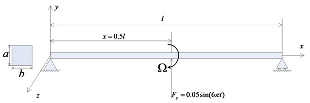
The external forces are as shown in Fig. 4, where , .
Fig. 4The external force acting on the structure
Two pairs of piezoelectric actuators and sensors are collocated at the 7th and 15th element in direction, respectively. The feedback gain is set to 6×10⁵, and the typical properties of piezoelectric material are as follows, –7.5, the voltage is 100 V, is 2×10⁴ Ω.
5.1. Dynamic responses of ZOAC and FOAC model
Fig. 5 shows the transverse responses of a beam spinning at 150 rad/s derived by AMM and FEM, respectively. The difference between the displacements derived by two different methods is obvious. The main reason is that AMM directly uses the analysis results of the vibration frequencies and modals in structural dynamics, which neglects the effect of a large overall motion. On the other hand, FEM allows a rigid multibody formalism to study flexible slender bodies directly [20]. Therefore, FEM could obtain more accurate dynamic responses of spinning flexible beams.
Fig. 6 illustrates the transverse responses of a spinning flexible beam at a speed of 50 rad/s based on ZOAC and FOAC model. The differences are so small since the effect of the rigid-flexible coupling terms is small. As a result, the ZOAC model is a valid dynamic model of a spinning flexible beam at low spinning speeds.
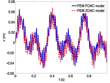
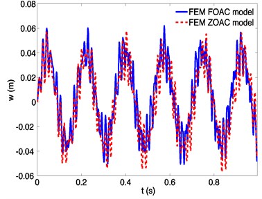
At 400 rad/s the differences in transverse responses of a spinning flexible beam predicted by the FOAC and ZOAC models are more apparent (Fig. 7). The differences are large due to the effect of the rigid-flexible coupling terms increases as spinning speed and cannot be neglected.
Fig. 5Dynamic responses of a spinning beam using assumed mode method (AMM) and finite element method (FEM), respectively, at a spinning speed 150 rad/s
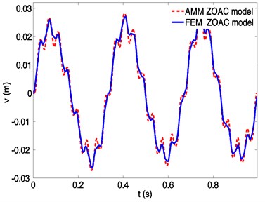
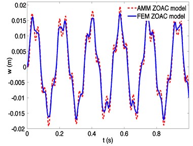
Fig. 6Dynamic responses of a spinning beam using finite element method based on FOAC model and ZOAC model, respectively, at a spinning speed 50 rad/s
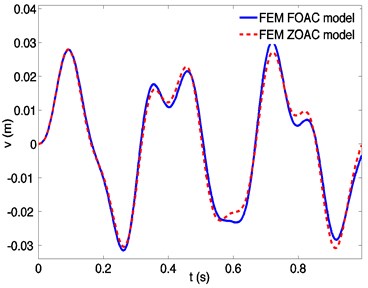
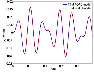
Fig. 7Dynamic responses of a spinning beam using finite element method based on FOAC model and ZOAC model, respectively, at a spinning speed 400 rad/s
The differences of transverse responses derived by a ZOAC and an FOAC model are investigated. Define values as following that reflect the similarity of the responses:
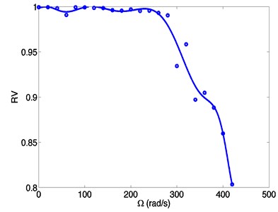
where , represent the displacements of an arbitrary point derived by a ZOAC model, and , represent the displacements of the same point derived by an FOAC model. If and are 1, it implies that the displacements derived by a ZOAC model and an FOAC model are the same. Corresponding values of 0 mean that the displacements are totally different.
Fig. 8 shows that the difference between the responses derived by the two models gets larger as the spinning speeds increase. The similarity decreases sharply at a speed over 280 rad/s, to 0.9 at about 320 rad/s, meaning that the difference is so large that the ZOAC model is not accurate any more. It can be seen that at higher spinning speeds, accounting for the effect of the rigid-flexible coupling is a key factor to obtain a more accurate dynamic response.
Fig. 8Similarity of dynamic responses of a spinning beam using finite element method based on FOAC model at different spinning speeds
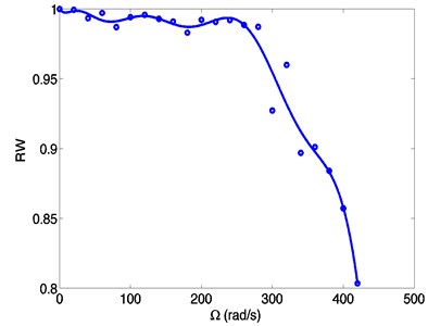
From the above discussions, the dynamic matrices are influenced by the effect of the rigid-flexible coupling terms, which increases as the spinning speeds increase. The effect is small and has little influence on the dynamic matrices at low speeds. Thus the dynamic responses derived by two different models are almost the same. In these low speed cases, the ZOAC model is valid. However, in high speed cases, the dynamic matrices change a lot since the coupling effect gets lager. The difference of the dynamic responses is obvious and the ZOAC model is no longer accurate.
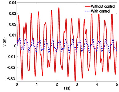
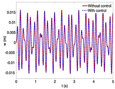
Fig. 9Dynamic responses of a spinning beam without and with control at a spinning speed 50 rad/s
5.2. Vibration control
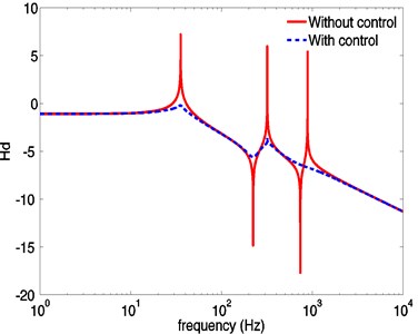
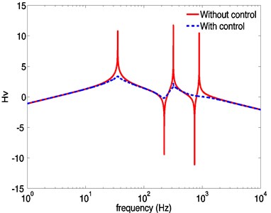
Numerical simulation of active vibration control of the spinning flexible beam in Figs. 9-10. It shows that the piezoelectric controllers increase system damping and result in an obvious vibration suppression of the spinning beam. The displacement and the velocity in direction are suppressed markedly, and the peak of dynamic response could be reduced about 78 %. There is no effect on response in direction due to the fact that the piezoelectric actuators only suppress the vibration perpendicular to the planes of piezoelectric films. Besides, since the beam is forced by centrifugal forces caused by eccentricity all the time, the transverse responses don’t decay asymptotically to zero.
Fig. 10Displacement frequency response a) and velocity frequency response b) without and with control
a)
b)
6. Conclusions
In this paper, finite element modeling and velocity feedback control strategy for the active vibration control of a high-speed spinning flexible mechanical-electric coupled beam are developed. The dynamic equations of a pinned-pinned spinning flexible Rayleigh beam accounting for the effect of the rigid-flexible coupling are derived in detail on the basis of a first order approximate coupling (FOAC) model, and a finite element method is used to obtain the dynamic responses. The numerical simulation of a spinning beam at different speeds concludes that a zero order approximate coupling (ZOAC) model is valid to be used as the dynamic model of a spinning flexible beam at low speeds, but invalid at high speeds. This problem is largely overcome by use of the FOAC model, which accounts for the effect of the rigid-flexible coupling. In addition, the vibration of the spinning beam can be suppressed effectively by the proposed velocity feedback controller.
References
-
Bauer Helmut F. Vibration of a rotating uniform beam, part I: orientation in the axis of rotation. Journal of Sound and Vibration, Vol. 72, Issue 2, 1980, p. 177-189.
-
Pai P. Frank, Qian Xin, Du Xingwen Modeling and dynamic characteristics of spinning Rayleigh beams. International Journal of Mechanical Sciences, Vol. 68, 2013, p. 291-303.
-
Dimentberg Fedor M. Flexural Vibrations of Rotating Shafts. Butterworths, London, 1961.
-
Bauer H. F., Eidel W. Vibration of a rotating uniform beam, part II: orientation perpendicular to the axis of rotation. Journal of Sound and Vibration, Vol. 122, Issue 2, 1988, p. 357-375.
-
Pai P. Frank Highly Flexible Structures: Modeling, Computation, and Experimentation. AIAA Education Series, 2007.
-
Irving H. Shames Energy and Finite Element Methods in Structural Mechanics. CRC Press, 1985.
-
Muszynska Agnieszka Rotordynamics. CRC Press, 2010.
-
Yamamoto Toshio, Yukio Ishida Linear and Nonlinear Rotordynamics: a Modern Treatment with Applications. John Wiley & Sons, Vol. 11, 2001.
-
Sheu G. J., Shih-Ming Yang Dynamic analysis of a spinning Rayleigh beam. International Journal of Mechanical Sciences, Vol. 47, Issue 2, 2005, p. 157-169.
-
Qian Xin, Guo Chang Lin, Xing Wen Du Vibration measurement and data analysis of a spinning shaft using a camera-based motion analysis system. Applied Mechanics and Materials, Vol. 29, 2010, p. 203-208.
-
Boukhalfa A. Dynamic analysis of a spinning laminated composite-material shaft using the hp-version of the finite element method. Advances in Vibration Analysis Research, 2011, p. 161-186.
-
Lee U., Jang I. J., Park I. W. Frequency-domain spectral element model of a uniform spinning shaft. Applied Mechanics and Materials, Vol. 224, 2012, p. 264-267.
-
Mustapha K. B., Zhong Z. W. Spectral element analysis of a non-classical model of a spinning micro beam embedded in an elastic medium. Mechanism and Machine Theory, Vol. 53, 2012, p. 66-85.
-
Chan K. T., et al. Revolving superposed standing waves in a spinning Timoshenko beam. Journal of Sound and Vibration, Vol. 331, Issue 4, 2012, p. 815-832.
-
Khadem S. E., Shahgholi M., Hosseini S. A. A. Two-mode combination resonances of an in-extensional rotating shaft with large amplitude. Nonlinear Dynamics, Vol. 65, Issue 3, 2011, p. 217-233.
-
Shahgholi Majid, Khadem Siamak Esmaeilzadeh Resonance analysis of gyroscopic nonlinear spinning shafts with parametric excitations and speed fluctuations. International Journal of Mechanical Sciences, Vol. 64, Issue 1, 2012, p. 94-109.
-
Shahgholi Majid, Khadem Siamak Esmaeilzadeh Resonances of an in-extensional asymmetrical spinning shaft with speed fluctuations. Meccanica, Vol. 48, Issue 1, 2013, p. 103-120.
-
Yoo H. H., Ryan R. R., Scott R. A. Dynamics of flexible beams undergoing overall motions. Journal of Sound and Vibration, Vol. 181, Issue 2, 1995, p. 261-278.
-
Mamandi Ahmad, Kargarnovin Mohammad H. Nonlinear dynamic analysis of an axially loaded rotating Timoshenko beam with extensional condition included subjected to general type of force moving along the beam length. Journal of Vibration and Control, Vol. 19, Issue 16, 2013, p. 2448-2458.
-
Valembois R. E., Fisette Paul, Samin Jean-Claude Comparison of various techniques for modelling flexible beams in multibody dynamics. Nonlinear Dynamics, Vol. 12, Issue 4, 1997, p. 367-397.
About this article
This work was supported by: (1) Funding of Jiangsu Innovation Program for Graduate Education (Grant No. CXZZ13_0148) and the Fundamental Research Funds for the Central Universities, (2) a Project Funded by the Priority Academic Program Development of Jiangsu Higher Education Institutions (PAPD).
