Abstract
The main goal of the active suspension system used in a vehicle is reducing the vehicle vibration. In this study, an adaptive control approach is applied to a nonlinear quarter car model with an active suspension system. An electromagnetic actuator is used in the active suspension system. The attractive aspect of the applied control method is not required to both vehicle parameters and actuator parameters. Using Lyapunov based stability analysis; it is shown that all the signals in the closed loop system are bounded. Hence, the applied controller ensures the vibration reduction of the nonlinear quarter car model. The simulation results show that the applied adaptive controller provide a good ride comfort despite the parametric uncertainties while keeping suspension travel and tire deflection in acceptable limits.
1. Introduction
Vehicle vibration is a serious cause of problem in automotive industry, because the undesired vibrations affect the passenger comfort and safety, and have a potential to cause mechanical failure on automobile parts. In this content vibration control becomes very important. The suspension systems isolate the force arisen from road roughness, and they are used to reduce the vehicle vibration arisen from different road conditions. There are three main types of suspension systems used for suppression of vibration in transportation systems. These are passive, semi-active and active suspension systems [1-4]. The passive systems consist of a damper and a spring [5, 6]. These types of suspension systems are not controllable. The controllable suspension systems are semiactive and active ones [1, 3]. Generally, in the semiactive suspension systems, controllable devices are used such as MR damper, etc. [7-11] When it comes to the active suspension systems, they are included an actuator, and offer a good performance in a wide frequency range. The active suspension systems are widely used in transportation systems [12-20]. Different types of actuators including electrohydraulic [21, 22], DC motor [23], PMSM (Permanent Magnet Synchronous Motor) [24] and electromagnetic [25-27] actuators are used in active controlled suspension systems. Electromagnetic actuators have a potential to be successful in vehicle vibration control. In particular, the electromagnetic actuators are preferred because of their efficiency and decreasing costs [27].
For several years, many researchers have been interested in control of suspension system and several active control methods are widely used. Intelligent control algorithms are utilized for active suspension systems. Demir, et al. [2] modeled and controlled a nonlinear half-vehicle car using hybrid fuzzy PID based intelligent controller which is combined fuzzy logic and classical PID approach. Guclu and Gulez [24] presented a neural network control for seat vibrations of a nonlinear full-vehicle model using PMSM actuator. Guclu [4] proposed a fuzzy logic controller for reducing the seat vibration of a nonlinear vehicle model. Besides, robust and adaptive control approaches also applied to active suspension systems. Akcay and Turkay [18] investigated the effect of tire damping on mixed H2/H∞ synthesis for half-car active suspensions using linear matrix inequalities. Onat, et al. [19, 20] designed an LPV (Linear Parameter Varying) based gain scheduling controller for active suspension systems and applied to full car model and quarter car model. The performance of the controller is evaluated by simulations and the results show that the developed control method successfully improves the ride comfort. Yagiz, et al. [28], and Yagiz and Yuksek [29] applied a robust control method for linear and nonlinear full vehicle model using sliding mode control to improve the ride comfort. Huang and Chen [30] designed a model-free adaptive sliding mode controller with self-tuning fuzzy compensation for an active vehicle suspension system. Yagiz, et al. [17] designed a nonchattering sliding mode control is combined with a single-input-single-output fuzzy logic controller and applied to active suspension systems for a nonlinear half-car model. Sharkawy [31] designed a fuzzy and an adaptive fuzzy control to active suspension system for providing good road handling and increasing the passenger comfort. Ozbulur [32] designed an adaptive compensator for a vehicle suspension system to improve ride comfort. Kaddisi, et al. [22] presented a nonlinear control strategy of an electrohydraulic active suspension system to control and reduce the car’s vertical motion and keep it to zero. The control strategy is based on a combination of backstepping and integrator forwarding. The simulation results show the effectiveness of the designed controller.
As understood from literature review given above, passenger comfort, road handling and limited suspension travel are crucial requirements of a successful suspension control. Moreover, the comfort and safety of the vehicle are changing dependent on the control methods. In order to control of suspension system, control methods based on the model parameters can be used. However, in practice, it is difficult to determine the actual system parameters. Many studies have been conducted on the dynamic characteristics of the vehicle and suspension system. There have been many researches on the vehicle system identification and many linear and nonlinear methods have been developed [33, 34]. Since the vehicle parameters are difficult to determine exactly, this affect the control performance especially in conventional control approaches. Hence, in order to provide good performance adaptive control method is chosen that can be coping with parametric uncertainty.
In traditional suspension systems, a passive hydraulic damper with a spring is used for vibration reduction. The vibration arisen from road irregularities is absorbed by the damper and converted into heat. The suspension system should absorb the road disturbance rapidly. This is difficult to achieve with a traditional passive suspension system. Besides, in automotive industry, electric car technologies are widespread because of oil prices, CO2 emissions, environmental sustainability, etc. These types of cars use battery which increases the vehicle weight. This increment adversely affects the comfort and safety. To provide passenger comfort, road handling and limited suspension travel, traditional passive suspension systems should be replaced with the semi-active and active suspension systems. Hydraulic and pneumatic systems can be used as an actuator in active suspension systems. However, Gysen, et al. [25, 26] reported that there are some disadvantages of hydraulic or pneumatic systems. For example, these systems have a relatively low bandwidth (around 1 Hz) and inefficient due to the need for a continuous pressurized system. On the other hand, electromagnetic suspension systems have a very small response time with a bandwidth in excess of 50 Hz. For this reason, they have good performance on absorbing the vibrations arisen from road disturbance and reacting in lane-change maneuvers. These actuators have a relatively high force density due to the tubular structure. Moreover, electromagnetic actuators have bidirectional power flow which allows both motor and generator modes [25, 26]. Different topologies are investigated by the researchers for the electromagnetic actuators. In this study, an electromagnetic actuator which is investigated and applied to vehicle systems by Gysen, et al. [25-27] is used as an actuator for active suspension system.
In this paper, an adaptive control approach is applied to nonlinear quarter car model in the presence of uncertain parameters in both vehicle and actuator. The attractive aspect of the applied control method is not required to both vehicle parameters and actuator parameters. Furthermore, for improving passenger comfort, this study focuses on reducing the vibration level of car body. Passenger comfort is provided by minimizing the force acting on the passenger. The electromagnetic actuator is used to implement the adaptive control. The rest of the paper is organized as follows. In Section 2, the problem formulation of nonlinear quarter car model with electromagnetic actuator is presented. The adaptive control development is given in Section 3. Section 4 provides the stability analysis of adaptive controller designed in Section 3. Lyapunov approach is used for the analysis. In Section 4, the designed adaptive control approach is utilized to nonlinear quarter car model using simulation studies. The results of the controller show the effectiveness of the controller on improvement of the ride comfort.
2. Problem formulation
In this study, a vibration control problem for a vehicle in the presence of parametric uncertainty is considered. To design an adaptive controller for the problem of vehicle vibration control, a nonlinear quarter car model with two degrees of freedom is offered. The quarter car models are widely used in the literature. It is assumed that the quarter car model reflects the many important characteristics of real suspension system and yet these models are simple. The nonlinear quarter car model which is studied in this paper is shown in Fig. 1.
Fig. 1A nonlinear quarter car model with electromagnetic actuator
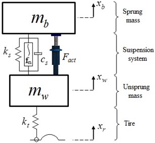
The model consists of a sprung mass, an unsprung mass, suspension components and a tire. In this model, the sprung mass represents the ¼ car body mass. The mass of wheel and the assembly of the axle are called as unsprung mass. The suspension system used in this study is an active controlled type suspension system which consists of a linear spring, a linear damping, a nonlinear spring and an electromagnetic actuator. Besides, the tire is modelled as a simple linear spring. Hence, the nonlinear quarter car model has two degrees of freedom, namely and . and are the vertical displacements of the sprung mass and unsprung mass, respectively. The roughness of the road is symbolized as . It is assumed that the tire is in point-contact with the road, so as the equation of the motion can be given in the following form:
where represents the sprung mass and describes the unsprung mass. The linear stiffness of the suspension spring symbolized as and the stiffness of the elastic tire denoted as . is the linear damping constant of suspension system. The nonlinear characteristic of the suspension system is defined as and modeled as cubic stiffness and defined as [2, 33]:
where is the nonlinear spring coefficient. ‘’ is the output force of the actuator which is produced by the electromagnetic actuator. Dynamics of the electromagnetic actuator is given in detailed in [25-27]. However, in the view of the fact that force-current dependency presented in [27], the complicated electromagnetic actuator dynamics can be simplified as:
where is approximated motor constant and is the amplitude of the current.
Property 1: The nonlinear quarter car model dynamics can be represented in matrix form as follows:
where , , describe the positive definite mass matrix, damping matrix and stiffness matrix, respectively. depicts the vector of the nonlinear suspension force and defined as . is the location vector of the electromagnetic actuator and depicted as . illustrates the disturbance input vector and defined as . , and represent the acceleration, velocity and displacement vectors, respectively.
Property 2: The nonlinear quarter car dynamics given in Eqs. (1), (2) and (5) can be parameterized as where contains the constant unknown mechanical system parameters including mass, damping, and linear and nonlinear stiffness. Then, it can be defined as follows:
denotes the known regression matrix that is a function of the displacement and velocity and described as:
Assumption 1: The subsequent control development is based on the assumption that and are measurable. Also, and are known and are bounded. Hence , and can be computed.
Assumption 2: The controller is designed under the constraint that the system parameters unknown, and the actuator parameter is uncertain, too.
3. Control formulation
As is well known, the vehicles are exposed the rough road conditions. The vibrations occur due to road roughness can cause damages to vehicles, unsafe driving condition, and unpleasant driving comfort. A key issue in the control of vehicle vibration is providing passenger comfort without compromising both road handling performance and suspension travel. Comfort and safety of the vehicle is changing dependent on the control methods. For vibration reduction, control methods based on the model parameters can be used. However, in practice, it is difficult to determine the actual system parameters. Since the vehicle parameters are difficult to determine exactly, this affect the control performance. On the other hand, adaptive control methods can cope with parametric uncertainties. Therefore, in this study, an adaptive control method applied to nonlinear quarter car model. The attractive aspect of the applied control method is not required to both vehicle parameters and actuator parameters.
3.1. Control objective
As is mentioned above, for vehicles, passenger comfort, road handling and limited suspension travel are crucial requirements of a successful suspension control. In this content, to improve the passenger comfort, this study focuses on reducing the vibration level of car body. In our final goal, we expect to reduce the vibration level of the car body called as sprung mass in Section 2. The objective of the controller is to develop a controller that regulate the vibration of sprung and unsprung masses to the desired value (0, 0). To quantify this control objective, an error signal can be defined as:
where is the displacement vector of the system and defined in Eq. (5). is the vector of desired vibration level of the system. It can be obviously said that the objective of vibration control is to force the vibration amplitude to zero. Therefore, the desired value should be equal to zero. Hence, the error signal and it is time derivative are defined as follows:
To further simplify the control design and stability analysis, an auxiliary error signal, denoted by , is also defined using error and time derivative of error as follows:
where denotes a constant diagonal positive-definite control gain matrix. Using , and their time derivatives, the auxiliary error signal can be written, as follows:
Remark 1. Based on the definition of the error signals given above, it is clear that if the control objective is met, then the acceleration objective of the study will be met. In other words, if the displacement and velocity of the vehicle is to be constrained to be bounded, the acceleration of the vehicle will be forced to bounded amplitude.
3.2. Open loop error system
The open-loop error system for can be obtained by taking the time derivative of Eq. (11) and premultiplying both sides of the resulting expression by and then substitute the system dynamics of Eq. (5) into the resulting expression to obtain the following equation:
Eq. (12) can be defined in a compact form using Property 2 as follows:
where and defined in Eq. (6) ,(7). After adding and subtracting the product to the right side of Eq. (13), we can rewrite the open-loop dynamics as follows:
where is the estimate error of the electromotor armature constant . For the simplicity, the term is used for the estimation of actuator force that is represented as follows:
where is the estimate of the .
3.3. Control design
Based on the previous development, an adaptive control law can be designed to regulate the vehicle vibration. Specifically, based on the open-loop error system given in Eq. (14) and the subsequent stability analysis, the control signal is defined as follows:
where is a constant diagonal positive-definite control gain matrix. is the parameter estimate vector and determined by an adaptation algorithm that is generated by the following update law:
where is a constant diagonal positive-definite adaptation gain matrix.
3.4. Closed loop error system
To facilitate the closed-loop error system development, the control input signal is substituted into the open-loop dynamics of given by Eq. (14) to obtain the following expression:
and simplifying the resulting expression using parameter estimation error of , the final expression of the closed-loop error dynamics for can be determined as:
where the parameter estimation error signals, denoted by and are defined as follows:
where is the estimate of electromagnetic actuator constant determined by an adaptation algorithm that is generated by the following update law:
By differentiating Eq. (20) and utilizing Eq. (17), the closed loop dynamics for can be expressed as:
Utilizing the same procedure, the is determined as follows:
4. Stability analysis
Theorem 1: Given the quarter car model defined by Eqs. (1) and (2), the adaptive controller consist of control input designed in Eq. (16), along with the update laws defined in Eq. (17) and Eq. (22), guarantees that the displacement and the velocity asymptotically driven to zero in the sense that:
Proof: To prove the Theorem 1, we define the following non-negative, continuously differentiable function denoted by as follows (Laypunov function candidate):
where is a positive constant adaptation gain and is a positive-definite constant adaptation gain matrix. After taking the time derivative of Eq. (26):
After substituting the closed loop-dynamics of Eq. (19) into Eq. (27), the following expression is obtained:
Applying the Eq. (23) and Eq. (24) to above expression and then canceling common terms, the time derivative of Lyapunov function obtained as follows:
From the above expression, it is clear that the time derivative of Lyapunov function is a nonpositive function. Therefore, is either constant or decreasing. Since is a non-negative function, it can be concluded that is bounded (). Furthermore, , and . Based on the fact that, , we can show that and and hence, and . It can be concluded that all of the signals remaining in the closed-loop system are bounded. Barbalat’s Lemma [35] can be utilized to obtain the result given in Eq. (25). The proof is completed.
5. Simulation and discussion
In this section, the proposed adaptive control method given in Section 3, is implemented to nonlinear quarter car model. For the demonstration of control performance on vibration suppression of proposed controller, the simulation studies are utilized. The proposed adaptive control algorithm applied to the nonlinear quarter car model with electromagnetic actuator, using Matlab-Simulink environment. The numerical parameters of the nonlinear quarter car model and the electromagnetic actuator are given in Table 1. Firstly, the vehicle is subjected to a bump road input which is used in the literature widely [2, 7, 36, 37]. The upward bump type road disturbance is used as shown in Fig. 2. For the proposed adaptive controller, the controller gains are selected as:
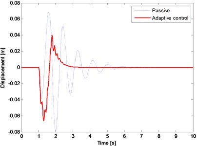
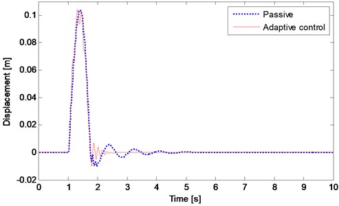
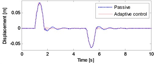
The performance of adaptive controlled system is compared with that of passive system. The results of the simulation employing upward bump function are shown in Figs. 3-8. Fig. 3 compares the displacement response of the vehicle body in terms of passive and adaptive controller. The dotted line depicts the passive case and the solid line shows the adaptive controlled case. It can be obviously seen that the adaptive controller effectively reduce the vibration amplitude of the vehicle body (sprung mass). Fig. 4 shows the suspension travel of the nonlinear quarter car model. As can be seen from figure, the suspension travel is both stayed in its limits and reduced by the adaptive controller. The tire deflection of the nonlinear quarter car model is illustrated in Fig. 5. As already noted above, the road holding ability concerning with tire deflection. It is clear from Fig. 5 that there is no remarkable change in tire deflection. Nonetheless, the maximum tire deflection for the adaptive controlled case does not exceed the passive one.
Table 1Nonlinear quarter car parameters
Parameter | Value | Parameter | Value |
Sprung mass – | 290 kg | Damping of the suspension – | 720 N.s/m |
Unsprung mass – | 45 kg | Nonlinear stiffness constant – | 16×104 N/m3 |
Stiffness of the suspension – | 17 000 N/m | Stiffness of the tire – | 170 000 N/m |
Fig. 2The road input used in simulation
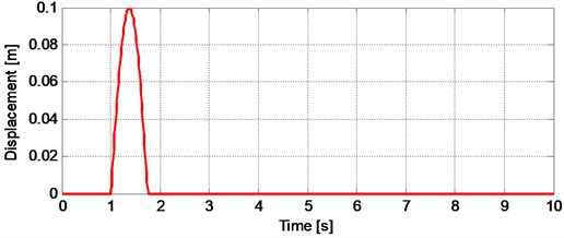
Fig. 3The displacement response of vehicle body (sprung mass)
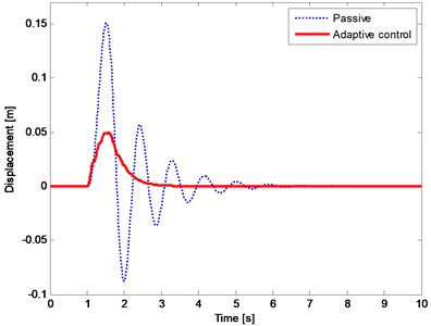
Fig. 4The suspension travel
The performance of the proposed controller was then evaluated with three different performance criteria. Since, the main aim of the adaptive controller design is to improve the ride comfort, the first criteria is defined as related with acceleration response of the body. It is called as ride index and defined as function of frequency weighted accelerations. For this purpose, the ride index calculation method is established [16]. A filter which is a better match to the international standard (ISO 2631) is used for calculation, which is given in [38]. The last two criteria are related with RMS values and peak levels of vibration. The comparison between passive and adaptive controlled cases by means of these performance criteria are given in Tables 2-4.
Table 2The ride index
Ride index | |
Passive | 0.0820 |
Adaptive control | 0.0212 |
Table 3The RMS values
RMS | ||||
- | ||||
Passive | 0.0506 | 1.7096 | 0.0269 | 0.0355 |
Adaptive control | 0.0194 | 1.1362 | 0.0205 | 0.0348 |
Table 4The maximum values
Peak value | ||||
- | ||||
Passive | 0.1508 | 5.0586 | 0.0793 | 0.1039 |
Adaptive control | 0.0498 | 4.4766 | 0.0662 | 0.1044 |
From the Table 2, it can be clearly seen that the adaptive controller performance is better than passive case in terms of ride index. Adaptive controller improves the ride index by 74.1 % as compared to passive case. RMS value of body displacement (), RMS value of body acceleration (), RMS value of suspension travel (-) and RMS value of tire deflection () are given in Table 3, too. Regarding the RMS values, the adaptive controller has a good performance. It has improvement by 61.7, 33.5, 23.8 and 2 % for body displacement, body acceleration, suspension travel, and tire deflection, respectively. Table 3 compares the passive and adaptive controlled case in term of peak value. The adaptive controller demonstrates a big reduction on both displacement and acceleration of body. Moreover, adaptive controller has achieved better improvement by means of suspension travel. Only the tire deflection performance is nearly the same with the passive case.
Fig. 5The tire deflection
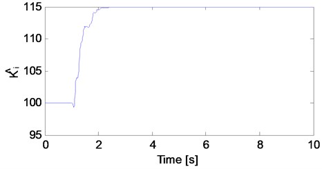
The parameter estimates of both the mechanical system and the electromagnetic actuator are presented in Figs. 6-8. Figs. 6 and 7 shows the estimates of the mass, damping and stiffness of the mechanical system. Fig. 8 illustrates the estimates of the electromagnetic actuator parameter. The initial values of the nonlinear quarter car parameter estimates are set to:
5.1. Simulation on series of a bump and a hole input
In order to validate the effectiveness of the designed controller a road input which consists of a bump and a hole is implemented to the nonlinear quarter ca model. The road input is shown in Fig. 9.
The results of the simulation employing a road profile which consists of a bump and a hole are shown in Figs. 10-12. The displacement responses of the vehicle body in terms of passive and adaptive controller are compared in Fig. 10.
Fig. 6The estimates of nonlinear quarter car model (mass and damping)
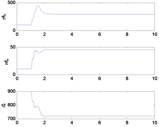
Fig. 7The estimates of nonlinear quarter car model (stiffness)
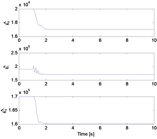
Fig. 8The estimate of electromagnetic actuator parameter
From the Fig. 10, it can be seen that the adaptive controller effectively reduce the vibration amplitude of the vehicle body under both bump and hole road inputs. The suspension travel of the nonlinear quarter car model under road profile given in Fig. 9 is illustrated in Fig. 11. The suspension travel limit is not exceeded under both bump and hole road profiles and reduced by the adaptive controller, too. Fig. 12 shows the tire deflection of the nonlinear quarter car model. It can be seen from Fig. 5 that there is no remarkable change in tire deflection.
Fig. 9The road input (a bump and a hole)
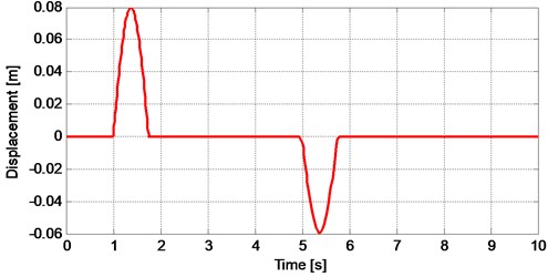
Fig. 10The displacement response of vehicle body under a road input consists of a bump and a hole
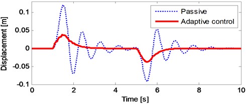
Fig. 11The suspension travel of vehicle under a road input consists of a bump and a hole
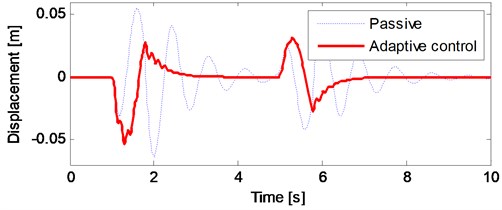
Fig. 12The tire deflection of vehicle under a road input consists of a bump and a hole
5.2. Simulation on stationary and non-stationary random road inputs
The road roughness can be defined using a white noise signal with a certain power spectral density. If a vehicle moves at a constant velocity, the road roughness can be expressed by the following equation [39]:
where is the road roughness, is a white noise signal, is the velocity of the vehicle and is the power spectral density of the road disturbance which is defined as [39-41]:
where is the spatial frequency, is the reference frequency and taken as 0.1. The value is the road roughness coefficient and provides a measure of the road roughness. is called as road roughness constant and shows the wavelengths of road. Generally, is taken as 2. is defined as , therefore the Eq. (30) can be rewritten as [39]:
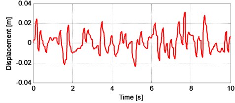
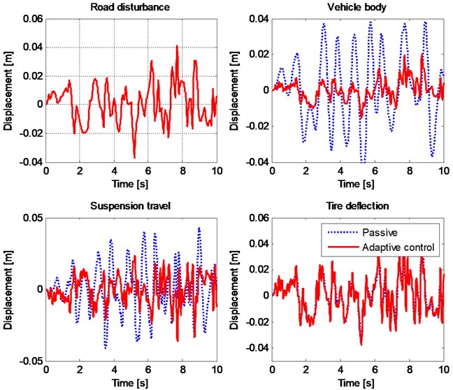
In Fig. 13, the time history of the stationary random road profile is illustrated. The vehicle speed is chosen as 20 m/s. The responses of the nonlinear quarter car model under stationary random road input are given in Figs. 14-16. Fig. 14 shows the comparison of the displacement responses of the vehicle body in terms of passive and adaptive controller under stationary random road input. It can be seen from the Fig. 14 that the adaptive controller achieves a good reduction along whole road profile.
Fig. 13The stationary random road input (V= 20 m/s)
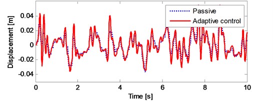
It can be seen from the Fig. 15 that the suspension travel of the nonlinear quarter car model is not exceeded the limit. Moreover, there is a reduction on the suspension travel of the vehicle. Fig. 16 shows the tire deflection of the nonlinear quarter car model and there is no remarkable change in tire deflection, too.
Fig. 14The displacement response of vehicle body under a stationary random road input
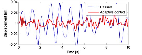
Fig. 15The suspension travel of vehicle under a stationary random road input
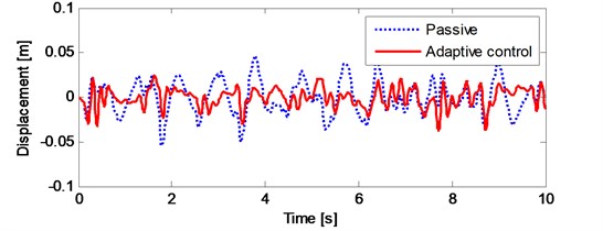
Fig. 16The tire deflection of vehicle under a stationary random road input
To validate the effectiveness of the proposed controller, lastly, the nonlinear quarter car model is simulated under non-stationary random road roughness. The equation used for stationary case can be adopted for the non-stationary case as follows [39]:
Fig. 17The results of vehicle under a non-stationary random road input
The initial speed of the vehicle is taken as 0 m/s. While the simulation, vehicle speed is change with the acceleration of 2 m/s2. Fig. 17 shows the non-stationary random road profile and the results of the simulation under the non-stationary random road profile. The results are very similar to stationary case. Again, the adaptive controller can effectively reduce the vibration amplitude of the vehicle body while the suspension travel limit is not exceeded. Moreover, it can be seen from Fig. 17 that there is no remarkable change in tire deflection, too.
Based on the simulation results, it can be concluded that the adaptive controller has a good performance on reducing the vehicle vibration. Especially, the applied controller is guarantees the ride comfort. The controller reduces the vibration level of body displacement and acceleration. Behind, it ensures the staying of suspension travel in its limits. The controller provides a reduction on suspension travel in terms of both RMS value and peak value, too. On the other hand, there is no remarkable change in tire deflection. Therefore, it can be concluded that, the adaptive controller that is applied to nonlinear quarter car model, increases the passenger comfort while the suspension deflection staying within acceptable limits and the tire-road contact has not changed.
6. Conclusion
In this study, an adaptive controller that can cope with uncertainties in both system and actuator parameters is proposed and applied to a nonlinear quarter car model with an electromagnetic actuator. In this control algorithm, the nonlinear quarter car model parameters and the electromagnetic actuator parameters are estimated by designed controller using the adaptation laws. Through the use of Lyapunov based stability analysis, it is shown that all the signals in the closed loop system are bounded. Therefore, the adaptive controller guarantees the vibration reduction of the nonlinear quarter car model. The advantage of the proposed controller is the ability to compensate parametric uncertainties in both system model and electromagnetic actuator. The simulation results prove that the applied adaptive controller provide a good ride comfort while keeping suspension travel and tire deflection in acceptable limits. It can be concluded that, the controller has a good performance on vibration reduction of nonlinear quarter car model despite the parametric uncertainties.
References
-
Cao D., Song X., Ahmadian M. Editors perspectives: road vehicle suspension design, dynamics, and control. Vehicle System Dynamics, Vol. 49, Issue 1, 2011, p. 3-28.
-
Demir O., Keskin I., Cetin S. Modeling and control of a nonlinear half-vehicle suspension system: a hybrid fuzzy logic approach. Nonlinear Dynamics, Vol. 67, Issue 3, 2012, p. 2139-2151.
-
Jin Y., Xuan L. Stochastic optimal active control of a half-car nonlinear suspension under random road excitation. Nonlinear Dynamics, Vol. 72, Issues 1-2, 2013, p. 185-195.
-
Guclu R. Fuzzy logic control of seat vibrations of a nonlinear full vehicle model. Nonlinear Dynamics, Vol. 40, Issue 1, 2005, p. 21-34.
-
Gonçalves J. P. C., Ambrosio J. A. C. Optimization of vehicle suspension systems for improved comfort of road vehicles using flexible multibody dynamics. Nonlinear Dynamics, Vol. 34, Issues 1-2, 2003, p. 113-131.
-
Nieto A. J., Morales A. L., Chicharro J. M., Pintado P. An adaptive pneumatic suspension system for improving ride comfort and handling. Journal of Vibration and Control, 2014.
-
Paksoy M., Guclu R., Cetin S. Semiactive self-tuning fuzzy logic control of full vehicle model with MR damper. Advances in Mechanical Engineering, Vol. 6, 2014, p. 816813.
-
Yıldız A. S., Sivrioğlu S., Zergeroğlu E., Çetin Ş. Nonlinear adaptive control of semi-active MR damper suspension with uncertainties in model parameters. Nonlinear Dynamics, Vol. 79, Issue 4, 2015, p. 2753-2766.
-
Song X., Ahmadian M., Southward S., Miller L. R. An adaptive semiactive control algorithm for magnetorheological suspension systems. Journal of Vibration and Acoustic, Vol. 127, Issue 5, 2005, p. 493-502.
-
Tusset A. M., Rafikov M., Balthazar J. M. An intelligent controller design for magnetorheological damper based on a quarter-car model. Journal of Vibration and Control, Vol. 15, Issue 12, 2009, p. 1907-1920.
-
Ahmadian M., Blanchard E. Non-dimensionalised closed-form parametric analysis of semi-active vehicle suspensions using a quarter-car model. Vehicle System Dynamics, Vol. 49, Issues 1-2, 2011, p. 219-235.
-
Metin M., Guclu R. Active vibration control with comparative algorithms of half rail vehicle model under various track irregularities. Journal of Vibration and Control, Vol. 17, Issue 10, 2010, p. 1525-1539.
-
Sezer S., Atalay E. Application of fuzzy logic based control algorithms on a railway vehicle considering random track irregularities. Journal of Vibration and Control, Vol. 18, Issue 8, 2012, p. 1177-1198.
-
Kalaivani R., Lakshmi P., Sudhagar K. Vibration control of vehicle active suspension system using novel fuzzy logic controller. International Journal of Enterprise Network Management, Vol. 6, Issue 2, 2014, p. 139-152.
-
Sakman L. E., Guclu R., Yagiz N. Fuzzy logic control of vehicle suspensions with dry friction nonlinearity. Sadhana, Vol. 30, Issue 5, 2005, p. 649-659.
-
Montezari-Gh M., Soleymani M. Genetic optimization of a fuzzy active suspension system based on human sensitivity to the transmitted vibrations. Proceedings of the Institution of Mechanical Engineers, Part D: Journal of Automobile Engineering, Vol. 222, Issue 10, 2008, p. 1769-1780.
-
Yagiz N., Hacioglu Y., Taskin Y. Fuzzy sliding-mode control of active suspensions. IEEE Transactions on Industrial Electronics, Vol. 55, Issue 11, 2008, p. 3883-3890.
-
Akçay H., Türkay S. Influence of tire damping on mixed H2/H∞ synthesis of half-car active suspensions. Journal of Sound and Vibration, Vol. 322, Issue 1, 2009, p. 15-28.
-
Onat C., Kucukdemiral I. B., Sivrioglu S., Yuksek I. LPV model based gain-scheduling controller for a full vehicle active suspension system. Journal of Vibration and Control, Vol. 13, Issue 11, 2007, p. 1629-1666.
-
Onat C., Kucukdemiral I. B., Sivrioglu S., Yuksek I., Cansever G. LPV gain-scheduling controller design for a nonlinear quarter-vehicle active suspension system. Transactions of the Institute of Measurement and Control, Vol. 31, Issue 1, 2009, p. 71-95.
-
Ekoru J. E., Pedro J. O. Proportional-integral-derivative control of nonlinear half-car electro-hydraulic suspension systems. Journal of Zhejiang University Science A, Vol. 14, Issue 6, 2013, p. 401-416.
-
Kaddissi C., Saad M., Kenné J.-P. Interlaced backstepping and integrator forwarding for nonlinear control of an electrohydraulic active suspension. Journal of Vibration and Control, Vol. 15, Issue 1, 2009, p. 101-131.
-
Zhang G., Zhang Y., Yu F. μ-Synthesis controller design for a DC-motor-based active suspension with parametric uncertainties. Journal of Vibration and Control, Vol. 19, Issue 4, 2013, p. 585-604.
-
Guclu R., Gulez K. Neural network control of seat vibrations of a non-linear full vehicle model using PMSM. Mathematical and Computer Modelling, Vol. 47, Issue 11, 2008, p. 1356-1371.
-
Gysen B. L., Janssen J. L., Paulides J. J., Lomonova E. A. Design aspects of an active electromagnetic suspension system for automotive applications. EEE transactions on Industry Applications, Vol. 45, Issue 5, 2009, p. 1589-1597.
-
Gysen B. L., Paulides J. J., Janssen J. L., Lomonova E. A. Active electromagnetic suspension system for improved vehicle dynamics. IEEE Transactions on Vehicular Technology, Vol. 59, Issue 3, 2010, p. 1156-1163.
-
Gysen B. L., Van der Sande T. P., Paulides J. J., Lomonova E. A. Efficiency of a regenerative direct-drive electromagnetic active suspension. IEEE Transactions on Vehicular Technology, Vol. 60, Issue 4, 2011, p. 1384-1393.
-
Yagiz N., Yuksek I., Sivrioglu S. Robust control of active suspensions for a full vehicle model using sliding mode control. JSME International Journal Series C Mechanical Systems, Machine Elements and Manufacturing, Vol. 43, Issue 2, 2000, p. 253-258.
-
Yagiz N., Yuksek I. Sliding mode control of active suspensions for a full vehicle model. International Journal of Vehicle Design, Vol. 26, Issues 2-3, 2001, p. 264-276.
-
Huang S.-J., Chen H.-Y. Adaptive sliding controller with self-tuning fuzzy compensation for vehicle suspension control. Mechatronics, Vol. 16, Issue 10, 2006, p. 607-622.
-
Sharkawy A. B. Fuzzy and adaptive fuzzy control for the automobiles’ active suspension system. Vehicle System Dynamics, Vol. 43, Issue 11, 2005, p. 795-806.
-
Ozbulur V. An adaptive compensator for a vehicle suspension system. Journal of Vibration and Control, 2014.
-
McGee C. G., Haroon M., Adams D. E., Luk Y. W. A frequency domain technique for characterizing nonlinearities in a tire-vehicle suspension system. Journal of Vibration and Acoustic, Vol. 127, 2005, p. 61-76.
-
Worden K., Hickey D., Haroon M., Adams D. E. Nonlinear system identification of automotive dampers: a time and frequency-domain analysis. Mechanical Systems and Signal Processing, Vol. 23, Issue 1, 2009, p. 104-126.
-
Slotine J. J., Li W. Applied Nonlinear Control. Prentice Hall, Englewood Cliff, 1991.
-
Weber P. A., Braaksma J. P. Towards a North American geometric design standard for speed humps. ITE Journal (Institute of Transportation Engineers), Vol. 70, Issue 1, 2000, p. 30-34.
-
Yang Z., Liang S., Sun Y., Zhu Q. Vibration suppression of four degree-of-freedom nonlinear vehicle suspension model excited by the consecutive speed humps. Journal of Vibration and Control, 2014.
-
Zuo L., Nayfeh S. A. Low order continuous-time filters for approximation of the ISO 2631-1 human vibration sensitivity weightings. Journal of Sound and Vibration, Vol. 265, 2003, p. 459-465.
-
He L., Qin G., Zhang Y., Chen L. Non-stationary random vibration analysis of vehicle with fractional damping. International Conference on Intelligent Computation Technology and Automation (ICICTA), Vol. 2, 2008, p. 150-157.
-
Du H., Li W., Zhang N. Integrated seat and suspension control for a quarter car with driver model. IEEE Transactions on Vehicular Technology, Vol. 61, Issue 9, 2012, p. 3893-3908.
-
Tyan F., Hong Y. F., Tu S. H., Jeng W. S. Generation of random road profiles. Journal of Advanced Engineering, Vol. 4, Issue 2, 2009, p. 1373-1378.
About this article

