Abstract
A unified solution for the in-plane vibration analysis of multi-span curved Timoshenko beams with general elastic boundary and coupling conditions by combining with the improved Fourier series method and Rayleigh-Ritz technique is presented in this paper. Under the current framework, regardless of boundary conditions, each of displacements and rotations of the curved Timoshenko beams is represented by the modified Fourier series consisting of a standard Fourier cosine series and several closed-form auxiliary functions introduced to ensure and accelerate the convergence of the series representation. All the expansion coefficients are determined by the Rayleigh-Ritz technique as the generalized coordinates. The convergence and accuracy of the present method are tested and validated by a lot of numerical examples for multi-span curved Timoshenko beams with various boundary restraints and general elastic coupling conditions. In contrast to most existing methods, the current method can be universally applicable to general boundary conditions and elastic coupling conditions without the need of making any change to the solution procedure.
1. Introduction
As one of the important structural components, curved Timoshenko beams has abundant engineering applications such as bridges, aircraft structures, space vehicles, turbo-machines and other industrial applications owing to their excellent engineering characteristics. Notably, these beams frequently work in complex environments and may suffer to arbitrary boundary restraints. Therefore, a good understanding of the vibration behavior of curved Timoshenko beams subjected to dynamic loads and general boundary conditions is of particular importance for satisfying the design requirements of strength and stiffness in practical designs.
In the last few decades, a number of computational techniques have been proposed and developed, such as Differential Quadrature method, the Galerkin method, meshless method, the Ritz method, Finite element method, dynamic stiffness method and discrete singular convolution method. An interesting review of the subject can be found in the review articles [1-3]. Culver and Oestel [4] presented a new method for determining the natural frequencies of multi-span horizontally curved girders. Lin and Lee [5] used closed-form solutions to analyze dynamic response of extensional circular Timoshenko beams with general elastic boundary conditions. Kang et al. [6] presented a systematic approach for the free in-plane vibration analysis of a planar circular curved beam system. Issa et al. [7] extended the dynamic stiffness matrix method to analyze the vibration of continuous circular curved beams with the clamped-clamped boundary condition. Chen [8, 9] developed an analytical technique to study the in-plane vibration of continuous curved beams. Wang [10] investigated the effects of rotary inertia and shear on natural frequencies of continuous circular curved beams undergoing in-plane vibrations by using the dynamic stiffness matrix method. Kawakami et al. [11] performed the in-plane and out-of-plane free vibration of horizontally curved beams with arbitrary shapes and variable cross-sections by an approximate method. Riedel and Kang [12] employed wave propagation techniques to study the free vibration of elastically coupled dual-span curved beams subject to classical boundary conditions. Lee [13] applied the pseudospectral method to analyze the free vibration of circularly curved multi-span Timoshenko beams with classical boundary and rigid coupling conditions. Huang et al. [14, 15] derived the in-plane and the out-of-plane transient response of a hinged-hinged and a clamped-clamped non-circular Timoshenko curved beam by using the dynamic stiffness matrix method and the numerical Laplace transform. Leung and Zhu [16] used finite element method to analyze the in-plane vibration of thin and thick curved beams with classical boundary conditions. Krishnan and Suresh [17] utilized a simple cubic linear beam element to study static and free vibration analysis of curved beams using finite element method. Chen [18] applied the differential transform method to investigate the in-plane vibration of arbitrarily curved beam structures. Yang et al. [19] studied free in-plane vibration of uniform and non-uniform curved beams with variable curvatures, including the effects of the axis extensibility, shear deformation and the rotary inertia by using the Galerkin finite element method. Ozturk [20] introduced the reversion method and finite element method to predict in-plane free vibration of a large deflected pre-stressed cantilever curved beam. Eisenberger and Efraim [21] presented an exact dynamic stiffness matrix for a circular beam with pinned-pinned and clamped-clamped boundary conditions.
In view of the aforementioned issues and concerns, it should be emphasized that most of the existing contributions were restricted to a single or two-span curved beam subjected to a limited set of classical supports. Little research has been devoted to the in-pane vibration problem of multi-span curved Timoshenko beams with general elastic boundary and coupling conditions. However, in practical engineering applications, the boundary and coupling conditions of multi-span curved Timoshenko beams may not always be classical boundary and rigid coupling conditions in nature, and there will always be some elastic boundary and coupling conditions. The in-plane vibration behaviors of multi-span curved Timoshenko beams with general boundary and coupling conditions have remained unsolved until now. Moreover, to the best of the authors’ knowledge, no unified, efficient and accurate solution is available in the literature for the in-plane vibration analysis of multi-span curved Timoshenko beams subjected to general elastic boundary and coupling conditions.
Recently, a modified Fourier series technique proposed by Li [22, 23] is widely used in the vibrations of plates and shells with general boundary constraints by Ritz method, e.g., [24-32]. Therefore, the present work can be considered as an extension of the method and attempts to provide a unified solution method for the in-plane vibration of multi-span curved Timoshenko beams with general elastic boundary and coupling conditions. Under the current framework, the modified Fourier series method together with the Rayleigh-Ritz procedure and the artificial stiffness-like spring technique is adopted to derive the theoretical formulation. The general elastic boundary and coupling constraints of the multi-span curved Timoshenko beams are realized by applying the artificial stiffness-like spring technique. Each of displacements and rotations of each curved Timoshenko beam is represented by the modified Fourier series consisting of a standard Fourier cosine series and several closed-form auxiliary functions introduced to ensure and accelerate the convergence of the series representation. Thereby, all the Fourier expanded coefficients are treated equally and independently as the generalized coordinates and are solved directly by using the Rayleigh-Ritz procedure. The convergence and accuracy of the present formulation are checked by a considerable number of convergence tests and comparisons. A variety of numerical examples are presented for the in-plane vibration of multi-span curved Timoshenko beams with general elastic boundary and coupling conditions, which may serve as benchmark solutions for validating new computational techniques in future.
2. Theoretical formulations
2.1. Geometrical configuration
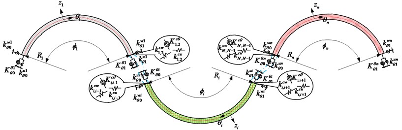
Fig. 1 shows a multi-span curved Timoshenko beam system, which consists of multiple curved beams coupled together via a set of joints, which are modeled by two groups of linear springs and one group of rotational springs. The use of the coupling springs between two adjacent curved beams allows accounting for the effects of some non-rigid or resilient connectors. The conventional rigid connectors can be considered as a special case when the stiffnesses of these springs become substantially large with reference to the bending rigidities of the involved curved beams. Each curved beam may also be independently supported on a set of elastic restraints at both ends. All the traditional intermediate supports and classical boundary conditions (i.e., the combinations of the simply supported (S), free (F), and clamped end conditions (C)) can be readily obtained from these general boundary conditions by accordingly setting the stiffness constants of the restraining springs to be equal to zero or infinity.
Fig. 1A multi-span curved Timoshenko beam subjected to general elastic boundary and coupling conditions
2.2. General boundary and coupling conditions
The Timoshenko model for a curved beam consists of three partial differential equations for the curved beam radial displacement , the tangential displacement and the rotation due to the bending of a cross section. Thus, The differential equations for the vibration of the th curved Timoshenko beam can expressed as[16]:
where is the angular frequency of the curved beam, , , , , and are the shear correction factor, the shear modulus, the cross-sectional area, the second moment of the area, the density of the beams and radius of curvature, respectively. The extensional strain , flexural strain , and shear strain component in the co-ordinate system are expressed in:
According to the linearly elastic theory, the normal force is linearly related to , while the bending moment is proportional to the change in curvature as in the technical theory of beams. The shear force-shear strain relation is the familiar one from curved Timoshenko beam theory. Thus:
From the previous reviews, in this study, the artificial stiffness-like spring technique is adopted to simulate the arbitrary boundary conditions and continuity conditions. With this method, the boundary and continuity conditions can be expressed as follows.
At 0:
At :
At the left end (of the first curved beam):
At the right end (of the th curved beam):
where, referring to Fig. 1, and denote the stiffnesses of the linear coupling springs in the -direction and -direction, and denote the stiffness of the rotational coupling spring at the junction of beams and , respectively; , , , are the stiffnesses of linear boundary springs, and , are the stiffnesses of the rotational boundary springs at the left and right ends of the curved Timoshenko beam , respectively.
All the conventional (homogeneous) curved beam boundary conditions can be considered as the special cases of Eqs. (10)-(21). For example, the simply supported end condition is easily modeled by simply setting the stiffnesses of the linear springs and rotational springs to be infinity and zero, respectively.
2.3. Admissible displacement functions
The admissible function is the essence of the weak formulation such as the Rayleigh-Ritz method to achieve an accurate, convergent and unified solution. The traditional Fourier series, a well-known form of admissible function for its excellent convergence, is limited to some very simple boundary conditions and would result in the discontinuities of the displacements and their derivatives as well. For the titled problem, the admissible functions are required not only to be regular enough to be differentiable, but also satisfy the geometry boundary conditions and continuity conditions at the junction. Recently, a modified Fourier series technique proposed by Li [22, 23] is widely used in the vibrations of plates and shells with different boundary conditions by Rayleigh-Ritz method, e.g., [24-32]. In this technique, each displacement of the structure under consideration is expressed as a conventional cosine Fourier series with the addition of several supplementary terms. The purpose of introducing the supplementary terms, taking the linear vibration of a classical beam for example, is explained here. Though an exact solution generally exists in the form of sine Fourier series when the beam is with the simply supported ends, it cannot be widely applicable for other boundary conditions. This is because that the original displacements and their derivatives of the edges exist potential discontinuities, in other words, the expanded expressions can’t be differentiated through term-by-term, which will make the solution not converge or converge slowly. The detail illustration is given in Ref. [22]. More information about the improved Fourier series can be seen in Refs. [23-32]. In this formulation, the modified Fourier series technique is adopted and extended to investigate the in-plane vibration of multi-span curved Timoshenko beams with general elastic boundary and coupling conditions.
Combining Eqs. (1)-(3) and (10)-(21), it is obvious that each displacement/rotation component of a multi-span curved Timoshenko beam is required to have up to the second derivative. Therefore, regardless of boundary and coupling conditions, each displacement/rotation component of the curved Timoshenko beams is assumed to be a one-dimensional modified Fourier series as:
where –1 and . denote the supplementary terms introduced to remove all the discontinuities potentially associated with the first-order derivatives at the boundaries and then ensure and accelerate the convergence of the series expansion of the curved beam displacement. , and are the expansion coefficients of standard cosine Fourier series. , and represent the corresponding expansion coefficients of the supplementary terms . These two supplementary terms are defined as:
It is easy to verify that:
2.4. Energy expressions
For the multi-span curved Timoshenko beams, the total strain energy () and kinetic energy () can be expressed as:
where and represent the strain energy and kinetic energy of the th curved Timoshenko beams, and is the potential energy expression in the connective springs related to th and 1th beams. The detailed expression of the , and can be written as:
2.5. Solution procedure
Having established the admissible displacement functions and energy functions of the multi-span curved Timoshenko beams, next, the corresponding coefficients of the admissible functions should be determined. In a weak formulation such as the Rayleigh-Ritz technique, however, all the expansion coefficients are considered as the generalized coordinates independent of each other. The strong and weak solutions are mathematically equivalent if they are constructed with the same degree of smoothness over the solution domain. The Rayleigh-Ritz technique will be adopted in this study since the solution can be obtained more easily. More importantly, such a solution process is better suitable for the future modeling of built-up structures.
The Lagrangian for the multi-span curved Timoshenko beams can be generally expressed as:
Substituting Eqs. (29) and (30) into the Lagrangian function Eq. (34), taking its derivatives with respect to each of the undetermined coefficients and making them equal to zero:
a total of equations can be obtained and they can be summed up in a matrix form as:
where and represent the stiffness matrix and the mass matrix of the beam, respectively. They are defined as:
The detail expressions for the sub-stiffness and sub-mass matrices are not shown here since they are easy to gain. According to the above formula, the general vibration characteristics of the multi-span curved Timoshenko beam will be obtained. Specifically, the frequencies (or eigenvalues) can be obtained directly by solving the Eq. (36), and the mode shapes will be acquired by substituting the corresponding eigenvectors into the series representations of displacement and rotation components. It should also be noted that the current method is particularly advantageous in obtaining other variables of interest such as power flows. Since the displacements are constructed sufficiently smoothly as required in a strong formulation, post-processing the solution can be done easily through appropriate mathematical operations, including term-by-term differentiations.
3. Numerical results and discussion
In this section, a comprehensive investigation concerning the in-plane free vibration of multi-span curved Timoshenko beams with various boundary and coupling conditions is given to demonstrate the accuracy and reliability of the present method. Throughout these examples, unless otherwise stated, the non-dimensional is used in the presentation, and the material and geometry properties of all the curved beams under consideration are: 7800 kg/m3 (1, 2,…, ), 0.3 (1, 2,…, ), 2.1×10¹¹ Pa ( 1, 2,…, ), 120° (1, 2,…, ), 1 m (1, 2,…, ), and 0.005 m×0.005 m (1, 2,…, ).
3.1. Determination of the boundary and coupling spring stiffness
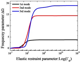
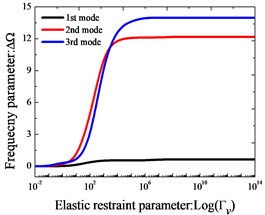
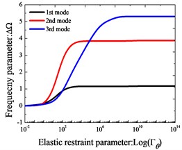
In the present work, the general boundary and coupling conditions are implemented by the artificial stiffness-like spring technique introduced to simulate the boundary forces and displacements, with the help of which, the general boundary and coupling conditions of the multi-span curved Timoshenko beams can be achieved by assigning the proper stiffness to the boundary and coupling springs. Taking a clamped end boundary (C) and rigid coupling (R) conditions for example, it can be realized by simply setting the stiffness of the entire springs to be “infinitely large” which is instead of a sufficiently large number in the actual calculation. So, it’s of great significance to investigate the effects of the spring stiffness of the boundary and coupling spring on the modal characteristics.
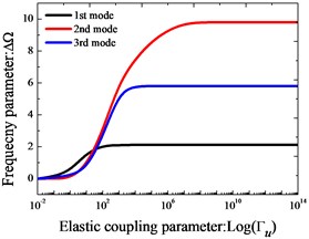
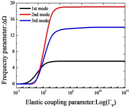
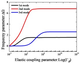
Effects of elastic boundary and coupling stiffness parameters on the frequency parameters of two-span curved Timoshenko beams are studied. In Fig. 2, variation of the lowest three frequency parameters versus the elastic boundary and coupling restraint parameters for two-span curved Timoshenko beams is shown. The elastic boundary restraint parameter refers to the situation that the beam is completely free at the left end boundary, rigid coupling restraint at the junction and elastically supported at the right end boundary, which is realized by only one group of spring component with the stiffness varying from 10-2 to 1014. According to Fig. 2, we can see that the frequency parameters exist the large change as the stiffness parameters increase in the certain range. In conclusion, the “infinitely large” in the actual calculations can be equal to 1×10¹⁴.
Fig. 2Variation of the frequency parameters ΔΩ versus the elastic restraint and coupling parameters for Timoshenko beams
Then the vibration analysis will be conducted and the frequencies and modal shapes of multi-span curved Timoshenko beams with different boundary conditions including the arbitrary classical, general elastic, general elastic coupling and their combinations will be presented. Here the left and first joint of the beam is taken as the example, considering three types of classical boundary conditions, three types of elastic boundary conditions and four types of coupling boundary conditions which are commonly encountered in engineering practices, the corresponding spring stiffness parameters are given as follows respectively:
Boundary conditions:
Coupling conditions:
As previously, the classical boundary conditions are defined in terms of the boundary spring parameter, the appropriateness of which deserves great attention and will be discussed and proved in later sub-sections. Notably, in this paper the boundary conditions of the multi-span curved Timoshenko beam are represented by several simple letter strings introduced to make the expression succinct (seen in the Fig. 3), i.e., identifies the three-span curved Timoshenko beams with , boundary conditions at the left and right ends boundary of beam, and , coupling conditions at joint 1 and joint 2, respectively.
3.2. Convergence study
Theoretically, there are infinite terms in the modified Fourier series solution. However, the series is numerically truncated and only finite terms are counted in actual calculations. The excellent convergence of the proposed method will be proved firstly. Considering the single curved Timoshenko beam as an element of the multi-span curved Timoshenko beams, thus the convergence can be studied by just checking the single curved Timoshenko beam’s. In the Table 1, the first six frequency parameters for and curved Timoshenko beams with eleven truncation schemes (i.e. 8, 9, 10, 11, 12, 13, 14, 15, 16, 17, 18) are presented. The frequency parameters of the beams are calculated by MATAB on a notebook. The configuration of the computer is: Inter Core(TM) i7-4970 CPU and 8 GB RAM. It is obvious that the present method has an excellent convergence, and is sufficiently accurate even when only a small number of terms are included in the series expressions. The maximum difference between the 12 and 18 is less than 0.051 % for the worst case. Besides, from the table, we can see that although the series are truncated as much as 50, the computing time is less 0.09 s. Unless otherwise stated, the truncated number of the displacement expressions will be uniformly selected as 12 in the following discussions.
Then the accuracy and reliability of the current formulation will be validated further by some more numerical examples. In each case, the convergence study is performed and for brevity purpose, only the converged results are presented here.
Table 1Convergence of the first six frequency parameters Ω for a single curved Timoshenko beam with C-C and F-F boundary conditions
1 | 2 | 3 | 4 | 5 | 6 | 1 | 2 | 3 | 4 | 5 | 6 | |
8 | 51.48 | 100.3 | 183.1 | 245.8 | 317.8 | 381.1 | 19.87 | 56.80 | 114.4 | 190.8 | 285.2 | 397.0 |
9 | 51.48 | 100.2 | 183.1 | 245.6 | 317.5 | 381.1 | 19.78 | 56.80 | 114.4 | 190.7 | 284.9 | 396.4 |
10 | 51.44 | 100.2 | 183.0 | 245.6 | 317.4 | 380.8 | 19.78 | 56.80 | 114.4 | 190.7 | 284.8 | 395.9 |
11 | 51.44 | 100.1 | 183.0 | 245.6 | 317.3 | 380.8 | 19.76 | 56.80 | 114.4 | 190.7 | 284.7 | 395.7 |
12 | 51.43 | 100.1 | 182.9 | 245.6 | 317.3 | 380.7 | 19.76 | 56.80 | 114.4 | 190.6 | 284.7 | 395.6 |
13 | 51.43 | 100.1 | 182.9 | 245.5 | 317.3 | 380.7 | 19.75 | 56.80 | 114.4 | 190.6 | 284.7 | 395.5 |
14 | 51.42 | 100.1 | 182.9 | 245.5 | 317.3 | 380.7 | 19.75 | 56.80 | 114.4 | 190.6 | 284.7 | 395.5 |
15 | 51.42 | 100.1 | 182.9 | 245.5 | 317.2 | 380.7 | 19.74 | 56.80 | 114.4 | 190.6 | 284.6 | 395.4 |
16 | 51.42 | 100.1 | 182.9 | 245.5 | 317.2 | 380.7 | 19.74 | 56.80 | 114.4 | 190.6 | 284.6 | 395.4 |
17 | 51.42 | 100.1 | 182.9 | 245.5 | 317.2 | 380.7 | 19.74 | 56.80 | 114.4 | 190.6 | 284.6 | 395.4 |
18 | 51.42 | 100.1 | 182.9 | 245.5 | 317.2 | 380.7 | 19.74 | 56.80 | 114.4 | 190.6 | 284.6 | 395.4 |
3.3. Multi-span curved Timoshenko beams with general boundary and coupling restraints
In this sub-section, multi-span curved Timoshenko beams with general boundary and coupling restraints are investigated. Firstly, the accuracy and reliability of the present method is validated by a verification study about the classical boundary conditions. In Tables 2-4, the first eight frequency parameters with classical boundary and rigid coupling conditions for single curved Timoshenko beam, two-span curved Timoshenko beam and three-span curved Timoshenko beam are presented, respectively. The results obtained from the FEM (ABAQUS) are also listed in the table as the reference, and the two results match very well. The differences between the two results are very small, and do not exceed 0.92 % for the worst case. Next, the in-plane vibration of multi-span curved Timoshenko beams with general elastic restraints will be studied.
Table 2Frequency parameters Ω for a single curved Timoshenko beam with different classical boundary conditions
Mode | ||||||||||
Present | FEM* | Present | FEM* | Present | FEM* | Present | FEM* | Present | FEM* | |
1 | 50.175 | 50.366 | 30.385 | 30.384 | 19.779 | 19.776 | 3.844 | 3.843 | 40.407 | 40.396 |
2 | 103.27 | 103.55 | 76.737 | 76.740 | 57.139 | 57.133 | 16.068 | 16.070 | 89.665 | 89.797 |
3 | 184.71 | 185.32 | 148.12 | 148.13 | 115.69 | 115.68 | 53.24 | 53.24 | 167.38 | 167.48 |
4 | 280.60 | 281.13 | 234.56 | 234.51 | 194.28 | 194.25 | 111.77 | 111.77 | 257.99 | 257.39 |
5 | 394.14 | 394.77 | 345.31 | 345.36 | 292.72 | 292.66 | 190.23 | 190.25 | 374.08 | 374.34 |
6 | 537.97 | 537.33 | 471.24 | 471.20 | 410.94 | 410.84 | 288.65 | 288.68 | 504.16 | 503.84 |
7 | 678.58 | 678.24 | 621.35 | 621.45 | 548.88 | 548.73 | 406.84 | 406.83 | 659.35 | 660.13 |
8 | 871.79 | 871.95 | 786.73 | 786.58 | 706.52 | 706.35 | 544.72 | 544.76 | 829.13 | 828.82 |
*The FEM results are form ABAQUS software | ||||||||||
Table 3Frequency parameters Ω for a two-span curved Timoshenko beam with different classical boundary conditions
Mode | ||||||||||
Present | FEM* | Present | FEM* | Present | FEM* | Present | FEM* | Present | FEM* | |
1 | 6.0095 | 6.0268 | 2.6165 | 2.6790 | 5.9400 | 5.9393 | 0.9826 | 0.9917 | 4.8761 | 4.8775 |
2 | 21.271 | 21.355 | 15.224 | 15.228 | 10.775 | 10.774 | 5.583 | 5.605 | 17.572 | 17.619 |
3 | 39.781 | 40.096 | 30.361 | 30.384 | 26.717 | 26.728 | 7.471 | 7.414 | 35.513 | 35.452 |
4 | 63.996 | 63.565 | 54.465 | 54.546 | 42.689 | 42.715 | 24.178 | 24.054 | 60.169 | 59.783 |
5 | 89.462 | 89.797 | 76.729 | 76.740 | 69.369 | 69.550 | 41.879 | 41.761 | 83.537 | 83.629 |
6 | 128.51 | 128.56 | 112.13 | 112.27 | 96.454 | 96.480 | 67.750 | 67.816 | 119.86 | 119.86 |
7 | 164.83 | 164.48 | 148.16 | 148.13 | 133.07 | 133.16 | 93.253 | 93.330 | 157.84 | 157.63 |
8 | 206.60 | 207.20 | 786.73 | 786.58 | 170.17 | 170.16 | 130.83 | 130.83 | 201.78 | 201.98 |
*The FEM results are form ABAQUS software | ||||||||||
Table 4Frequency parameters Ω for a three-span curved Timoshenko beam with different classical boundary conditions
Mode | ||||||||||
Present | FEM* | Present | FEM* | Present | FEM* | Present | FEM* | Present | FEM* | |
1 | 3.7242 | 3.7150 | 1.2770 | 1.2829 | 2.4610 | 2.4609 | 0.5704 | 0.5730 | 2.0351 | 2.0198 |
2 | 6.6241 | 6.6359 | 3.7794 | 3.7831 | 7.1872 | 7.1861 | 2.0940 | 2.0782 | 5.7446 | 5.7586 |
3 | 12.917 | 12.963 | 11.519 | 11.524 | 7.9489 | 7.9423 | 5.0785 | 5.0696 | 12.107 | 12.078 |
4 | 25.576 | 25.561 | 20.204 | 20.192 | 17.296 | 17.304 | 7.2865 | 7.3351 | 22.485 | 22.495 |
5 | 37.095 | 37.055 | 30.397 | 30.385 | 28.778 | 28.758 | 15.235 | 15.241 | 34.004 | 33.939 |
6 | 53.729 | 53.758 | 46.921 | 46.902 | 39.009 | 39.023 | 27.269 | 27.243 | 50.196 | 50.189 |
7 | 71.283 | 71.390 | 62.487 | 62.495 | 54.833 | 54.815 | 38.089 | 38.092 | 66.462 | 66.550 |
8 | 85.488 | 85.646 | 76.729 | 76.751 | 73.932 | 73.921 | 54.281 | 54.296 | 81.550 | 81.701 |
*The FEM results are form ABAQUS software | ||||||||||
Tables 5-7 show the first eight frequency parameters of single curved Timoshenko beam, two-span curved Timoshenko beam and three-span curved Timoshenko beam subjected to classical-elastic restraints and elastic boundaries, respectively. Besides, due to the lack of the open reported reference results and to be used as the comparison, the contrast results obtained using an FEM (ABAQUS) model are also given in Tables 5-7. An excellent agreement is achieved between the current and the FEM solutions. Finally, the in-plane vibrations of multi-span curved Timoshenko beams with general elastic boundary and coupling restraints are presented.
Table 5Frequency parameters Ω for a single curved Timoshenko beam with different elastic boundary conditions
Mode | ||||||||||
Present | FEM* | Present | FEM* | Present | FEM* | Present | FEM* | Present | FEM* | |
1 | 40.422 | 40.392 | 6.0279 | 6.0268 | 30.379 | 30.379 | 10.411 | 10.412 | 51.944 | 51.944 |
2 | 89.646 | 89.757 | 21.352 | 21.355 | 76.685 | 76.689 | 34.648 | 34.649 | 103.37 | 103.38 |
3 | 167.37 | 167.43 | 66.572 | 66.565 | 148.01 | 148.03 | 83.464 | 83.464 | 188.04 | 188.05 |
4 | 257.27 | 257.10 | 128.58 | 128.56 | 234.05 | 234.08 | 151.77 | 151.78 | 279.93 | 279.95 |
5 | 373.97 | 374.04 | 213.19 | 213.20 | 344.79 | 344.84 | 240.53 | 240.56 | 403.43 | 403.48 |
6 | 502.77 | 502.62 | 315.79 | 315.76 | 469.28 | 469.36 | 348.80 | 348.84 | 532.41 | 534.42 |
7 | 658.81 | 659.25 | 439.47 | 439.62 | 619.61 | 619.72 | 477.05 | 477.08 | 695.95 | 696.19 |
8 | 824.37 | 824.33 | 581.93 | 581.93 | 778.92 | 779.14 | 624.80 | 624.91 | 849.83 | 850.06 |
*The FEM results are form ABAQUS software | ||||||||||
Table 6Frequency parameters Ω for a two-span curved Timoshenko beam with different elastic boundary conditions
Mode | ||||||||||
Present | FEM* | Present | FEM* | Present | FEM* | Present | FEM* | Present | FEM* | |
1 | 4.9212 | 4.9475 | 0.5005 | 0.8976 | 2.6791 | 2.6790 | 2.6791 | 2.6790 | 6.0279 | 6.0265 |
2 | 17.533 | 17.618 | 6.039 | 6.089 | 15.228 | 15.227 | 10.411 | 10.412 | 21.352 | 21.352 |
3 | 35.505 | 35.450 | 10.746 | 10.845 | 30.397 | 30.381 | 15.235 | 20.407 | 40.370 | 40.389 |
4 | 60.124 | 60.132 | 27.821 | 27.599 | 54.539 | 54.539 | 34.666 | 34.649 | 66.536 | 66.547 |
5 | 83.395 | 83.615 | 48.025 | 47.940 | 76.729 | 76.715 | 54.539 | 54.546 | 89.720 | 89.742 |
6 | 119.87 | 119.84 | 73.712 | 73.815 | 112.21 | 112.23 | 83.464 | 83.464 | 128.47 | 128.47 |
7 | 157.84 | 157.83 | 101.57 | 101.58 | 148.09 | 148.09 | 112.24 | 112.27 | 167.33 | 167.36 |
8 | 201.71 | 202.02 | 139.77 | 139.85 | 191.66 | 191.66 | 151.77 | 151.78 | 212.97 | 213.00 |
*The FEM results are form ABAQUS software | ||||||||||
Table 7Frequency parameters Ω for a three-span curved Timoshenko beam with different elastic boundary conditions
Mode | ||||||||||
Present | FEM* | Present | FEM* | Present | FEM* | Present | FEM* | Present | FEM* | |
1 | 2.0251 | 2.0198 | 0.8059 | 0.8075 | 1.2843 | 1.2830 | 1.2843 | 1.2829 | 3.7169 | 3.7147 |
2 | 5.7442 | 5.7586 | 2.8042 | 2.7927 | 3.7831 | 3.7831 | 3.7831 | 3.7831 | 6.6352 | 6.6359 |
3 | 12.053 | 12.078 | 5.2625 | 5.2651 | 11.519 | 11.524 | 10.415 | 10.411 | 12.954 | 12.962 |
4 | 22.500 | 22.495 | 10.304 | 10.306 | 20.204 | 20.191 | 11.519 | 11.525 | 25.540 | 25.558 |
5 | 33.976 | 33.938 | 16.707 | 16.710 | 30.397 | 30.383 | 20.204 | 20.191 | 37.058 | 37.051 |
6 | 50.200 | 50.189 | 29.551 | 29.539 | 46.884 | 46.899 | 34.666 | 34.649 | 53.729 | 53.751 |
7 | 66.460 | 66.543 | 42.468 | 42.453 | 62.487 | 62.487 | 46.884 | 46.902 | 71.356 | 71.371 |
8 | 81.543 | 81.694 | 58.182 | 58.208 | 76.7 29 | 76.733 | 62.487 | 62.491 | 85.598 | 85.609 |
*The FEM results are form ABAQUS software | ||||||||||
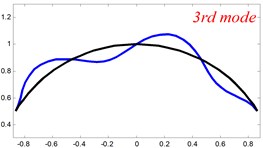
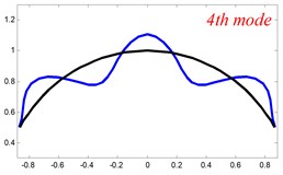
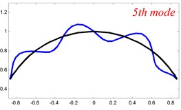
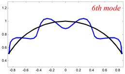
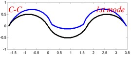
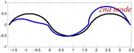
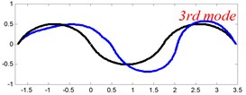
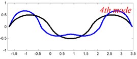
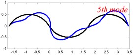
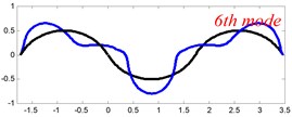
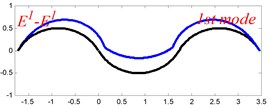
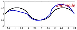
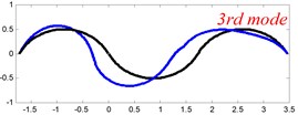
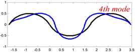
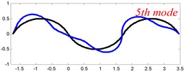
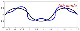
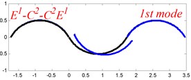
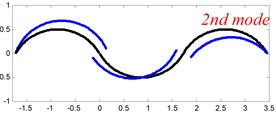
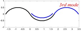
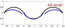
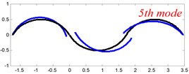
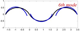
In Tables 8 and 9, the detailed comparisons between results obtained by the present method and those provided by FEM solutions (ABAQUS) are presented, in which two types of multi-span curved Timoshenko beams (two-span curved Timoshenko beam and three-span curved Timoshenko beam) are included. It’s very clear that the current results have a great agreement with the reference data. In order to improve our comprehension of the effects of elastic boundary and coupling restraints on vibration characteristic of multi-span curved Timoshenko beams. The first six mode shapes of the single curved Timoshenko beam, two-span curved Timoshenko beam and three-span curved Timoshenko beam with different boundary and coupling restraints are given in Figs. 4-6, respectively. It can be seen that the elastic boundary and coupling restrain have a quite significant effect on the vibration characteristics of the beam structures.
Fig. 3A simple letter string of a multi-span curved Timoshenko beam
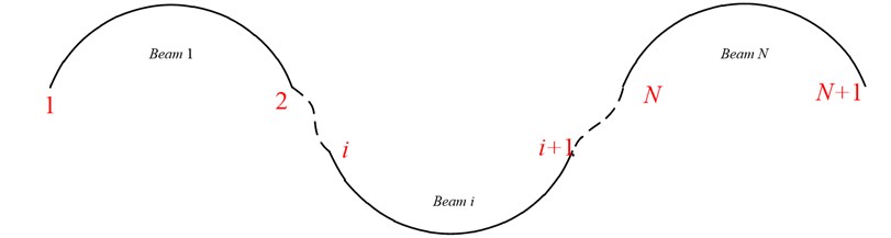
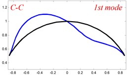
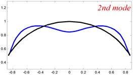
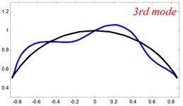
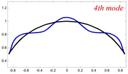
Fig. 4The lowest six mode shapes for single curved Timoshenko beams with different boundary conditions
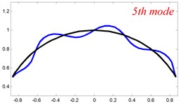
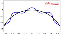
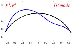
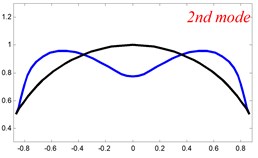
According to the above analysis, it can be seen that the current method is reliable to make correct predictions of the modal characteristics for the multi-span curved Timoshenko beam with the elastic restraint boundary and coupling conditions as well as the classical boundary and rigid coupling conditions. It should be noted that for sake of simplifying the research, only the three-span curved Timoshenko beam is studied in this paper, but it doesn’t mean the current method is restricted to the three-span. Through the theoretical formulations, it can be seen that when the number of the curved beams is added, which merely increases the dimensional of the stiffness matrix and mass stiffness, the corresponding analysis can be easily obtained.
Table 8Frequency parameters Ω for a two-span curved Timoshenko beam with different elastic coupling conditions
Mode | ||||||||||
Present | FEM* | Present | FEM* | Present | FEM* | Present | FEM* | Present | FEM* | |
1 | 3.7459 | 3.8427 | 3.7635 | 3.8427 | 0.0468 | 0.0471 | 0.0147 | 0.0152 | 6.0279 | 6.0261 |
2 | 16.066 | 16.068 | 6.0004 | 6.0261 | 10.775 | 10.773 | 0.0147 | 0.0160 | 21.352 | 21.351 |
3 | 40.316 | 40.392 | 16.149 | 16.068 | 30.379 | 30.380 | 0.0736 | 0.0573 | 40.370 | 40.385 |
4 | 53.236 | 53.221 | 21.392 | 21.355 | 42.709 | 42.700 | 0.0736 | 0.0581 | 66.536 | 66.547 |
5 | 89.610 | 89.786 | 53.002 | 53.221 | 76.699 | 76.707 | 5.9249 | 5.9382 | 89.720 | 89.727 |
6 | 111.74 | 111.75 | 66.666 | 66.565 | 96.46 | 96.43 | 10.415 | 10.411 | 128.47 | 128.48 |
7 | 167.54 | 167.48 | 111.78 | 111.75 | 148.05 | 148.07 | 26.717 | 26.724 | 167.33 | 167.35 |
8 | 190.40 | 190.20 | 128.02 | 128.56 | 170.09 | 170.04 | 34.666 | 34.648 | 212.97 | 213.02 |
*The FEM results are form ABAQUS software | ||||||||||
Table 9Frequency parameters Ω for a three-span curved Timoshenko beam with different elastic coupling conditions
Mode | ||||||||||
Present | FEM* | Present | FEM* | Present | FEM* | Present | FEM* | Present | FEM* | |
1 | 2.9826 | 2.9699 | 3.5457 | 3.5304 | 7.1096 | 7.1025 | 3.9340 | 3.9321 | 3.7152 | 3.7147 |
2 | 3.0338 | 3.0255 | 4.8516 | 4.8533 | 14.4988 | 14.4950 | 7.9195 | 7.9195 | 6.6360 | 6.6359 |
3 | 9.8554 | 9.9093 | 7.5732 | 7.5835 | 30.380 | 30.382 | 10.415 | 10.411 | 12.962 | 12.962 |
4 | 17.469 | 17.459 | 16.892 | 16.881 | 37.192 | 37.191 | 23.442 | 23.421 | 25.557 | 25.558 |
5 | 36.253 | 36.227 | 19.151 | 19.127 | 48.616 | 48.599 | 30.250 | 30.253 | 37.045 | 37.047 |
6 | 46.308 | 46.244 | 28.191 | 28.247 | 76.703 | 76.715 | 34.666 | 34.649 | 53.745 | 53.747 |
7 | 54.380 | 54.373 | 54.312 | 54.480 | 87.846 | 87.843 | 63.628 | 63.588 | 71.362 | 71.367 |
8 | 84.173 | 84.292 | 60.592 | 60.555 | 105.051 | 105.007 | 75.809 | 75.795 | 85.574 | 85.591 |
*The FEM results are form ABAQUS software | ||||||||||
Fig. 5The lowest six mode shapes for two-span curved Timoshenko beams with different boundary conditions
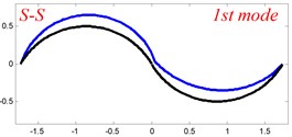
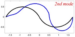
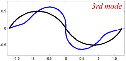
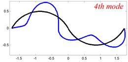
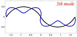
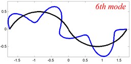
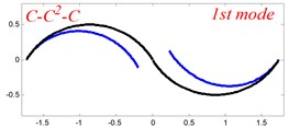
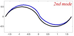
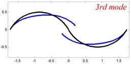
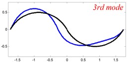
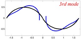
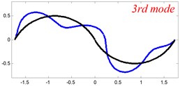
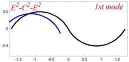
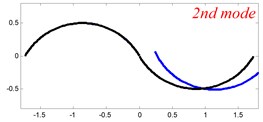
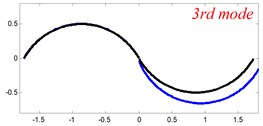
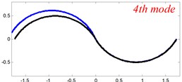
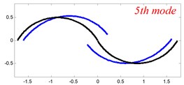
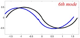
Fig. 6The lowest six mode shapes for three-span curved Timoshenko beams with different boundary conditions
4. Conclusions
A unified method is presented for in-plane vibration analysis of multi-span curved Timoshenko beams with general elastic boundary and coupling conditions. Each of the displacements and rotations of every curved Timoshenko beam, is expressed as a modified Fourier series, which is constructed as the linear superposition of a standard one-dimensional Fourier cosine series supplemented with auxiliary polynomial functions introduced to eliminate all the relevant discontinuities with the displacement and its derivatives at the ends and accelerate the convergence of series representations. All the expansion coefficients are determined by the Rayleigh-Ritz technique as the generalized coordinates. The excellent accuracy and reliability of the current solutions are confirmed by comparing the present results with FEM solution, and numerous new results for multi-span curved Timoshenko beams with various classical cases, classical-elastic restraints, and elastic boundary and coupling conditions, are presented, which can be served as the benchmark solutions for other computational techniques in the future research.
References
-
Laura P., Filipich C., Cortinez V. In-plane vibrations of an elastically cantilevered circular arc with a tip mass. Journal of Sound and Vibration, Vol. 115, Issue 3, 1987, p. 437-446.
-
Laura P., Maurizi M. Recent research on vibrations of arch-type structures. The Shock and Vibration Digest, Vol. 19, Issue 1, 1987, p. 6-9.
-
Chidamparam P., Leissa A. W. Vibrations of planar curved beams, rings, and arches. Applied Mechanics Reviews, Vol. 46, Issue 9, 1993, p. 467-483.
-
Culver C., Oestel D. Natural frequencies of multispan curved beams. Journal of Sound and Vibration, Vol. 10, Issue 3, 1969, p. 380-389.
-
Lin S. M., Lee S. Y. Closed-form solutions for dynamic analysis of extensional circular Timoshenko beams with general elastic boundary conditions. International Journal of Solids and Structures, Vol. 38, Issue 2, 2001, p. 227-240.
-
Kang B., Riedel C., Tan C. Free vibration analysis of planar curved beams by wave propagation. Journal of Sound and Vibration, Vol. 260, Issue 1, 2003, p. 19-44.
-
Issa M., Wang T., Hsiao B. Extensional vibrations of continuous circular curved beams with rotary inertia and shear deformation. 1. Free vibration. Journal of Sound and Vibration, Vol. 114, Issue 2, 1987, p. 297-308.
-
Chen S. In-plane vibration of continuous curved beams. Nuclear Engineering and Design, Vol. 25, Issue 3, 1973, p. 413-431.
-
Chen S. Coupled twist-bending waves and natural frequencies of multispan curved beams. The Journal of the Acoustical Society of America, Vol. 53, Issue 4, 1973, p. 1179-1183.
-
Tung-Ming W., Guilbert M. P. Effects of rotary inertia and shear on natural frequencies of continuous circular curved beams. International Journal of Solids and Structures, Vol. 17, Issue 3, 1981, p. 281-289.
-
Kawakami M., Sakiyama T., Matsuda H., Morita C. In-plane and out-of-plane free vibrations of curved beams with variable sections. Journal of Sound and Vibration, Vol. 187, Issue 3, 1995, p. 381-401.
-
Riedel C. H., Kang B. Free vibration of elastically coupled dual-span curved beams. Journal of Sound and Vibration, Vol. 290, Issue 3, 2006, p. 820-838.
-
Lee J. Free vibration analysis of circularly curved multi-span Timoshenko beams by the pseudospectral method. Journal of Mechanical Science and Technology, Vol. 21, Issue 12, 2007, p. 2066-2072.
-
Huang C.-S., Tseng Y.-P., Lin C.-J. In-plane transient responses of arch with variable curvature using dynamic stiffness method. Journal of Engineering Mechanics, Vol. 124, Issue 8, 1998, p. 826-835.
-
Huang C., Tseng Y. P., Chang S. H., Hung C. L. Out-of-plane dynamic analysis of beams with arbitrarily varying curvature and cross-section by dynamic stiffness matrix method. International Journal of Solids and Structures, Vol. 37, Issue 3, 2000, p. 495-513.
-
Leung A., Zhu B. Fourier p-elements for curved beam vibrations. Thin-Walled Structures, Vol. 42, Issue 1, 2004, p. 39-57.
-
Krishnan A., Suresh Y. A simple cubic linear element for static and free vibration analyses of curved beams. Computers and Structures, Vol. 68, Issue 5, 1998, p. 473-489.
-
Chen C.-N. DQEM analysis of in-plane vibration of curved beam structures. Advances in Engineering Software, Vol. 36, Issue 6, 2005, p. 412-424.
-
Yang F., Sedaghati R., Esmailzadeh E. Free in-plane vibration of general curved beams using finite element method. Journal of Sound and Vibration, Vol. 318, Issue 4, 2008, p. 850-867.
-
Ozturk H. In-plane free vibration of a pre-stressed curved beam obtained from a large deflected cantilever beam. Finite Elements in Analysis and Design, Vol. 47, Issue 3, 2011, p. 229-236.
-
Eisenberger M., Efraim E. In-plane vibrations of shear deformable curved beams. International Journal for Numerical Methods in Engineering, Vol. 52, Issue 11, 2001, p. 1221-1234.
-
Li W. L. Free vibrations of beams with general boundary conditions. Journal of Sound and Vibration, Vol. 237, Issue 4, 2000, p. 709-725.
-
Li W. L. Comparison of Fourier sine and cosine series expansions for beams with arbitrary boundary conditions. Journal of Sound and Vibration, Vol. 255, Issue 1, 2002, p. 185-194.
-
Du J., et al. An analytical method for the in-plane vibration analysis of rectangular plates with elastically restrained edges. Journal of Sound and Vibration, Vol. 306, Issues 3-5, 2007, p. 908-927.
-
Du J. T., Li W. L., Zhang X. Free in-plane vibration analysis of rectangular plates with elastically point-supported Edges. Journal of Vibration and Acoustics – Transactions of the ASME, Vol. 132, Issue 3, 2010, p. 031002.
-
Shi D., Wang Q., Shi X., Pang F. A series solution for the in-plane vibration analysis of orthotropic rectangular plates with non-uniform elastic boundary constraints and internal line supports. Archive of Applied Mechanics, Vol. 85, Issue 1, 2015, p. 51-73.
-
Shi X., Shi D., Li W. L., Wang Q. A unified method for free vibration analysis of circular, annular and sector plates with arbitrary boundary conditions. Journal of Vibration and Control, 2014, p. 1077546314533580.
-
Jin G., Ye T., Chen Y., Su Z., Yan Y. An exact solution for the free vibration analysis of laminated composite cylindrical shells with general elastic boundary conditions. Composite Structures, Vol. 106, 2013, p. 114-127.
-
Jin G., Ye T., Ma X., Chen Y., Su Z., Xie X. A unified approach for the vibration analysis of moderately thick composite laminated cylindrical shells with arbitrary boundary conditions. International Journal of Mechanical Sciences, Vol. 75, 2013, p. 357-376.
-
Chen Y., Jin G., Liu Z. Flexural and in-plane vibration analysis of elastically restrained thin rectangular plate with cutout using Chebyshev-Lagrangian method. International Journal of Mechanical Sciences, Vol. 89, 2014, p. 264-278.
-
Jin G., Ma X., Shi S., Ye T. A modified Fourier series solution for vibration analysis of truncated conical shells with general boundary conditions. Applied Acoustics, Vol. 85, 2014, p. 82-96.
-
Jin G., Ye T., Jia X. A general Fourier solution for the vibration analysis of composite laminated structure elements of revolution with general elastic restraints. Composite Structures, Vol. 109, 2014, p. 150-168.
Cited by
About this article

The authors would like to thank the anonymous reviewers for their useful and constructive comments.
