Abstract
In this paper, a modified Fourier-Ritz approach is adopted to analyze the free vibration of orthotropic annular sector thin plates with general boundary conditions, internal radial line and circumferential arc supports. In the present method, regardless of boundary conditions, the displacements of the sector plates are invariantly expressed as a standard Fourier cosine series and several auxiliary closed-form functions. These auxiliary functions are introduced to eliminate any potential discontinuities of the original displacement function and its derivatives throughout the whole domain including its edges, and then to effectively enhance the convergence of the results. Since the displacement field is constructed to be adequately smooth in the whole solution domain, an accurate solution can be obtained by using Ritz procedure based on the energy functions of the sector plates. The excellent accuracy and reliability of the current solutions are compared with the results found in the literature, and numerous new results for annular sector plates with various boundary conditions are presented. New results are obtained for annular sector plates subjected to elastic boundary restraints and arbitrary internal radial line and circumferential arc supports in both directions, and they may be served as benchmark solutions for future researches.
1. Introduction
Orthotropic annular sector thin plates are widely used in many engineering applications such as ships, curved bridge decks, aeronautical and space structures and other industrial applications due to their excellent engineering features. The orthotropic annular sector thin plates in these applications can be subjected to various boundary conditions, such as classical restraints, elastic supports and their combinations. In addition, the internal radial line and circumferential arc supports may be placed to reduce the magnitude of dynamic and static stresses and displacements of the plates as well as satisfy special functional requirements. Therefore a thorough understanding of the vibration behaviors of orthotropic annular sector thin plates with general boundary restraints, internal radial line and circumferential arc supports is of great interest for the designers to realize proper and comparatively accurate design of machines and structures.
In recent decades, the wide use of annular sector thin plate structures has motivated a huge amount of research efforts in developing the more accurate and applicable model and methods for analyzing their dynamic behaviors. Onoe [1] presented a mathematical method on basis of Love’s theory for contour vibrations of isotropic circular plates. Mcgee et al. [2] used a novel Ritz method to analyze free vibration of the sectorial plate with complete free boundary conditions. Wang and Thevendran [3] employed the Rayleigh-Ritz method to solve the free vibration problem of annular plates with internal axisymmetric supports. Wang et al. [4] extended the differential quadrature method to study the free vibration analysis of annular plates with classical boundary conditions. Later, Wang et al. [5] developed the differential quadrature method to analyze the free vibration of circular annular plates with classical boundary conditions and non-uniform thickness. Furthermore, Wang [6, 7] extended the differential quadrature method to analyze the free vibration of thin sector plates with various sector angles and six combinations of classical boundary conditions. Irie et al. [8] employed Ritz method to the free vibration of ring-shaped polar-orthotropic sector plates with classical boundary conditions. Singh et al. [9] used Rayleigh-Ritz method to analyze the transverse vibrations of circular plates with variable thickness and classical boundary conditions. Wong et al. [10] investigated the sensitivity of changes in displacement mode shapes of annular plates relative to the hole size and obtained approximations to frequencies and mode shapes of circular plates with variable thickness by using mode subtraction method. Houmat [11] presented a sector Fourier p-element on basis of finite element method for free vibration analysis of sectorial plates with classical boundary conditions. Chen et al. [12] applied a meshless method for free vibration analysis of circular and rectangular clamped plates with clamped boundary condition. Seok and Tiersten [13, 14] presented a variational approximation procedure for free vibration analysis of annular sector cantilever plates. Aghdam et al. [15] performed bending analysis of thin annular sector plates with clamped boundary condition by extended Kantorovich method. Li [16] employed finite strip method to study the free vibration of circular and annular sectorial thin plates subject to classical boundary conditions. Kim and Yoo [17] utilized a novel analytical solution to flexural responses of annular sector thin plates with classical boundary conditions. Mirtalaie and Hajabasi [18] studied the free vibration of annular sector thin plates with classical boundary conditions by using differential quadrature method.
A review of the scientific literature in this field reveals that the majority of the existing free vibration investigation mainly focused on the isotropic annular sector plate which has the same material property along different directions, while the reported work on the free vibration of the orthotropic annular sector thin plate is little. Most of the contributions on free vibration analysis of orthotropic annular sector thin plates with classical boundary supports are confined. In addition, orthotropic annular sector thin plates with internal radial line and circumferential arc supports are widely encountered in the engineering practices. Without these intermediate supports, the plates may undergo large deformation and acute shaking and eventually lead to structural failure. The only work focused on this subject is that Liew et al. [19] presented the vibrations of Thick isotropic annular sector plates with classical boundary conditions. However, a variety of possible elastic boundary condition cases which may not always be classical in nature can be encountered in practice. The existing solution procedures are often only customized for a specific set of different boundary conditions, and thus typically require constant modifications of the trial functions and corresponding solution procedures to adapt to different boundary cases. Therefore, the use of the existing solution procedures will result in very tedious calculations and be easily inundated with various classical boundary conditions and their combinations. To the best of authors’ knowledge, there are no reported solutions on the free vibration of orthotropic annular sector thin plates with general boundary conditions, internal radial line and circumferential arc supports in the literature. Therefore, it is necessary and of great significance to develop a unified, efficient and accurate formulation which is capable of universally dealing with orthotropic annular sector thin plates subjected to general boundary conditions, internal radial line and circumferential arc supports.
The purpose of the present study is to develop an efficient and accurate solution for free vibration analysis of orthotropic annular sector thin plates subjected to general boundary restraints, internal radial line supports, circumferential arc supports. In a previous study, a modified Fourier series technique proposed by Li [20, 21] is widely used in the vibrations of plates and shells with general boundary conditions by Ritz method, e.g., [22-30]. Therefore, the present work can be considered the combination of the modified Fourier series technique and Ritz method to present a modified Fourier-Ritz approach for free vibration of orthotropic annular sector thin plates subjected to general boundary conditions, internal radial line and circumferential arc supports. Under the current framework, regardless of boundary conditions, the displacements of the sector plates are invariantly expressed as a standard Fourier cosine series and several auxiliary closed-form functions. These auxiliary functions are introduced to eliminate any potential discontinuities of the original displacement function and its derivatives, throughout the whole domain including its edges, and then to effectively enhance the convergence of the results. Since the displacement field is constructed to be adequately smooth in the whole solution domain, an accurate solution can be obtained by using Ritz procedure based on the energy functions of the sector plates. The excellent accuracy and reliability of the current solutions are compared with the results found in the literature, and numerous new results for annular sector plates with various boundary conditions are presented. New results are obtained for annular sector plates subjected to elastic boundary restraints and arbitrary internal radial line and circumferential arc supports in both directions, and they may serve as benchmark solutions for future researches.
2. Theoretical formulations
2.1. Description of the model
Fig. 1 shows a orthotropic annular sector thin plate with uniform thickness , inner radius , outer radius , width of plate in the radial direction and sector angle . The geometry and dimensions are defined in an orthogonal cylindrical coordinate system . A local coordinate system is also shown in the Fig. 1, which will be used in the analysis. Since the main focus of this paper is to develop a unified solution for the vibration analysis of orthotropic annular sector thin plates with general boundary conditions, thus, in order to satisfy the request, the artificial spring boundary technique is adopted here, in which each boundary of a plate is assumed to be restrained by one group of linear springs () and one group of rotational springs () to simulate the given or typical boundary conditions. The stiffness of the boundary springs can take any value from zero to infinity. By assigning the stiffness of the boundary springs with various values, it is equivalent to impose different boundary forces on the mid-plane of the plate. For example, the clamped boundary conditions are essentially obtained by setting the spring stiffness substantially larger than the bending rigidity of the plate.
2.2. Governing equations and boundary conditions
The governing equation of motion for the free vibration of orthotropic annular sector thin plates can be written as:
where is the sector plate deflection, are the standard bending rigidities in the classical lamination theory. For an orthotropic annular sector thin plate, the stiffness constants are related to the lamina engineering constants and the plate thickness as:
In terms of the flexural displacement, the bending and twisting moment and transverse shearing forces can be expressed as:
Fig. 1Schematic diagram of annular sector thin plate with arbitrary boundary condition
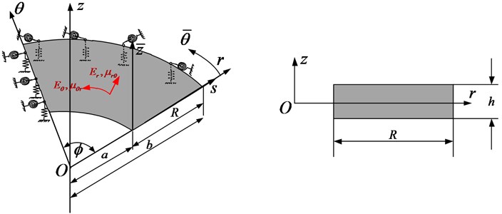
In this study, the general boundary conditions along each edge will be described in terms of two restraining springs, a linear spring and a rotational spring , where subscripts , , and represent the springs at the boundary edges of the plate respectively, as shown in Fig. 1. Accordingly, the boundary conditions become:
Eqs. (11)-(14) represent a set of general boundary conditions. By setting the spring stiffnesses to appropriate values, all the classical homogeneous boundary conditions can be readily simulated.
From Eqs. (6)-(10), the boundary conditions can be finally written as:
At 0:
At :
At 0:
At :
2.3. Admissible displacement functions
Mathematically, it is often desired to express the displacement, , in the form of a Fourier series expansion because Fourier functions constitute a complete set and exhibit an excellent numerical stability. Unfortunately, the conventional Fourier series expression will generally have a convergence problem along the boundary edges except for a few simple boundary conditions. In addition, without being uniformly convergent, the derivatives of a Fourier series cannot be obtained simply through term-by-term differentiation. To overcome these problems, the displacement function will be here expressed as a more robust form of Fourier series expansion:
where the eight supplementary terms are introduced to deal with any possible discontinuities or jumps at the boundaries which are potentially associated with the displacement function and its derivatives when they are periodically extended onto the entire solution domain. It should be noted that these discontinuities are not inherently related to the displacement function over the solution domain; instead they are the artifact resulting from the Fourier series representation of the displacement solution.
The four -functions in the direction and -functions in the direction in Eq. (23) are here chosen as:
It is easy to verify that their first and third derivatives are mostly equal to zero along the boundary edges except for:
It can be proven mathematically that the series expression in Eq. (23) is able to expand and uniformly converge to any function for . Also, this series can be simply differentiated, through term-by-term, to obtain the uniformly convergent series expansions for up to the fourth-order derivatives. Mathematically, an exact displacement (or classical) solution is a particular function for which satisfies the governing equation at each field point and the boundary conditions at every boundary point.
2.4. Solution procedure
Once the admissible displacement functions and energy functions of the sector plate are established, the following task is to determine the coefficients in the admissible functions. Because of its simplicity and high accuracy, Ritz method is widely used in the vibration analysis of structural elements as a very powerful tool. In the Ritz method, the solutions can be obtained by minimizing the energy functional with respect to the coefficients of the admissible functions.
The strain energy of the sector plate is given as:
By neglecting the rotary inertia, the kinetic energy of an orthotropic annular sector thin plate can be written as:
As mentioned in Sections 2.1 and 2.2, each boundary of a sector plate is assumed to be restrained by one group of linear springs () and one group of rotational springs () to simulate the given or typical boundary conditions. Therefore, the deformation strain energy () stored in the boundary springs during vibration can be defined as:
The Lagrangian functional () of the plates during vibration can be expressed in terms of the energy expressions:
Substituting Eqs. (34)-(36) and Eq. (23) into Eq. (37) and performing the Ritz procedure with respect to each unknown coefficient, the equations of motion for plates can be yielded and are given in the matrix form:
where:
In Eq. (38), the is the stiffness matrix of the plate, and the is the mass matrix. For conciseness, the detailed expression for stiffness and mass matrices will not be shown here. By solving the Eq. (38), the frequencies (or eigenvalues) of orthotropic annular sector thin plates can be readily obtained and the mode shapes can be yielded by substituting the corresponding eigenvectors into series representations of displacement.
3. Numerical results and discussion
In this section, a systematic comparison between the current solutions and other methods is carried out to validate the excellent accuracy, reliability and feasibility of the present method. Unless otherwise stated, the non-dimensional is used in the presentation, and the material and geometry properties of orthotropic annular sector thin plates under consideration are: 7800 kg/m3, 70 GPa, 40, 7.3 GPa, 0.3, 90, 1 m, 2 and 0.005.
3.1. Determination of the boundary spring stiffness
In the present work, the general boundary conditions of the structure are implemented by introducing artificial spring boundary technique to separately simulate the boundary forces and displacements. As previously mentioned, the case of general boundary conditions of the plates can be easily simulated by assigning proper stiffness values to the boundary springs, for instance, a clamped boundary (C) can be readily achieved by simply setting the stiffness of the entire springs to be infinitely large. However, the “infinitely large” is represented by a sufficiently large number in actual calculations. Thus, effects of the spring stiffness of boundary springs on the modal characteristics should be investigated.
Effects of elastic boundary and coupling stiffness parameters on the non-dimensional frequency parameters of orthotropic annular sector thin plates are studied. A frequency parameter which is defined as the difference of the non-dimensional frequency parameter to those of the elastic restraint parameters to 10-2, i.e., 10-2 is used in the calculation. The plates under consideration are completely clamped at boundaries 0, , and free at boundary 0, while at edge , the plates are elastically supported by only one group of spring component with stiffnesses varying from 10-2 to 1016. In Fig. 2(a), the influences of the line springs on frequency parameters are given. It is shown that the frequency parameter almost stays unchanged when the non-dimensional stiffness of the liner springs is larger than 109 or smaller than 104. In Fig. 2(b), the influences of the rotation springs on frequency parameters are given. It is shown that the frequency curve changes greatly within the stiffness range from 103 to 108. Based on the analysis, it can be found the frequency parameters exist the large change as the stiffness parameters increase in the certain range.
In the following discussion, vibration frequencies and modal shapes of annular sector plates with arbitrary classical boundary conditions, general elastic boundary conditions and their combinations will be presented. Taking edge 0 for example, the corresponding spring stiffness parameters for three types of classical boundary conditions and three types of elastic boundary conditions which are commonly encountered in engineering practices are given as follows:
The appropriateness of defining the classical boundary conditions in terms of boundary spring parameters will be proved by several examples in later sub-sections. For the sake of simplicity, a simple letter string is employed to represent the boundary condition of the annular sector plate, circular sector plate, annular plate and circular plate, such as the FCSE identifies the annular sector plate with , , and boundary conditions at boundaries 0, 0, and , respectively.
3.2. Convergence study
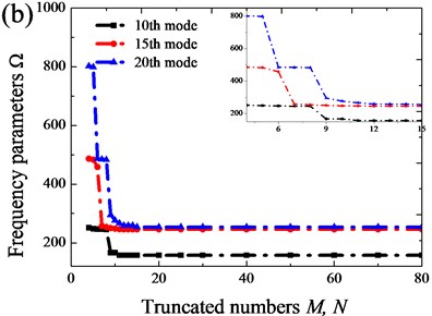
In this sub-section, the convergence of orthotropic annular sector plates with different boundary conditions is studied. The first eight frequency parameters for CCCC and FFFF orthotropic annular sector plates with different truncated number and (i.e. 8-14) are given in Table 1. The Table shows the proposed method has fast convergence. The maximum discrepancy for the worst case between the truncated configuration 12 and 14 is less than 0.004 %. In order to fully illustrate the convergence of the present method, the frequency parameters of the higher mode (10th, 15th and 20th) with various truncated numbers , subjected to CCCC and FFFF boundary conditions are shown in Fig. 3. The highly desired convergence characteristics are observed: (a) sufficiently accurate results can be obtained with only a small number of terms in the series expansions; (b) the solution is consistently refined as more terms are included in the expansions; (c) the frequency parameters for higher-order modes tend to converge slower. Thus, an adequate truncation number should be dictated by the desired accuracy of the interesting largest natural frequencies. In view of the excellent numerical behavior of the current solution, the truncation numbers will be simply set as 12 in the following calculations. To further validate the accuracy and reliability of the current solution, more numerical examples will be presented.
Fig. 2Variation of the frequency parameters Ω versus the elastic boundary restraint parameters for annular sector plate: a) transverse spring stiffness; b) rotation spring stiffness
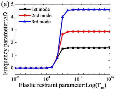
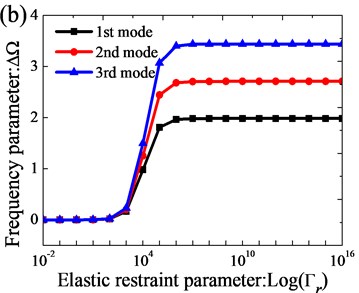
Fig. 3Variations of frequency parameter Ω with respect to truncated number M and N: a) FFFF; b) CCCC
3.3. Orthotropic annular sector thin plates with general boundary conditions
The target of this sub-section is to validate whether the present method can fit to solve the free vibration of orthotropic annular sector thin plates with general boundary conditions. First, a verification study about the classical boundary conditions is carried out to validate the accuracy and reliability of present method. In Tables 2 and 3, the first eight frequency parameters with different classical boundary conditions for isotropic annular sector thin plates and orthotropic annular sector thin plates are presented, respectively. In order to compare, the reference results taken from Ref. [18] and obtained using an FEM (ABAQUS) model are also given there. A great agreement can be obtained from the comparison. Next, we will focus on the free vibration of orthotropic annular sector thin plates with general elastic restraints. In Table 4, the detail comparisons between results obtained by the present method and those provided by FEM solutions (ABAQUS) are presented, in which nine types of elastic boundary conditions including classical-elastic case and complete elastic case are included. It is obvious that the current results match very well with the referential data. Based on the above analysis, it implies that the current method is able to make correct predictions for the modal characteristics of orthotropic annular sector thin plates with not only classical boundary but also elastically restrained boundary.
Table 1Convergence of frequencies parameters Ω for annular sector plate with CCCC and FFFF boundary conditions
Boundary conditions | Mode number | ||||||||
1 | 2 | 3 | 4 | 5 | 6 | 7 | 8 | ||
CCCC | 8 | 88.838 | 89.265 | 90.382 | 92.702 | 96.822 | 103.30 | 112.57 | 128.41 |
9 | 88.838 | 89.265 | 90.382 | 92.702 | 96.823 | 103.30 | 112.58 | 124.78 | |
10 | 88.838 | 89.265 | 90.381 | 92.702 | 96.821 | 103.30 | 112.55 | 124.78 | |
11 | 88.838 | 89.265 | 90.381 | 92.702 | 96.820 | 103.30 | 112.55 | 124.76 | |
12 | 88.838 | 89.265 | 90.381 | 92.702 | 96.820 | 103.30 | 112.55 | 124.76 | |
13 | 88.838 | 89.265 | 90.381 | 92.702 | 96.820 | 103.30 | 112.55 | 124.76 | |
14 | 88.838 | 89.265 | 90.381 | 92.702 | 96.820 | 103.30 | 112.55 | 124.76 | |
FFFF | 8 | 2.3039 | 2.3588 | 5.5209 | 6.6546 | 10.370 | 13.820 | 16.793 | 24.198 |
9 | 2.3017 | 2.3530 | 5.5201 | 6.6527 | 10.370 | 13.819 | 16.792 | 24.198 | |
10 | 2.3017 | 2.3530 | 5.5201 | 6.6526 | 10.370 | 13.819 | 16.792 | 24.197 | |
11 | 2.3013 | 2.3517 | 5.5199 | 6.6523 | 10.370 | 13.819 | 16.791 | 24.197 | |
12 | 2.3013 | 2.3517 | 5.5199 | 6.6522 | 10.370 | 13.819 | 16.791 | 24.197 | |
13 | 2.3012 | 2.3516 | 5.5199 | 6.6521 | 10.370 | 13.819 | 16.791 | 24.197 | |
14 | 2.3012 | 2.3516 | 5.5199 | 6.6521 | 10.370 | 13.819 | 16.791 | 24.197 | |
Table 2Frequency parameters Ω for isotropic annular sector plate with different classical boundary conditions
Boundary conditions | Methods | Mode number | |||||||
1 | 2 | 3 | 4 | 5 | 6 | 7 | 8 | ||
FSFS | Present | 21.067 | 66.722 | 81.604 | 146.41 | 176.12 | 176.9 | 274.57 | 298.37 |
DQM | 21.067 | 66.722 | 81.604 | 146.41 | 176.12 | 176.9 | – | – | |
FEM | 21.032 | 66.498 | 81.46 | 145.66 | 175.83 | 176.51 | 273.51 | 297.25 | |
SSSS | Present | 68.379 | 150.98 | 189.6 | 278.39 | 283.59 | 387.62 | 438.96 | 443.89 |
DQM | 68.379 | 150.98 | 189.6 | 278.39 | 283.59 | 387.62 | – | – | |
FEM | 68.112 | 150.55 | 189.12 | 277.75 | 282.4 | 386.99 | 437.32 | 442.9 | |
CSCS | Present | 107.57 | 178.82 | 269.49 | 305.84 | 346.46 | 476.3 | 487.39 | 508.57 |
DQM | 107.57 | 178.82 | 269.49 | 305.84 | 346.46 | 476.3 | – | – | |
FEM | 107.41 | 178.48 | 269.11 | 305.35 | 345.51 | 475.56 | 485.84 | 507.83 | |
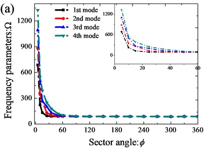
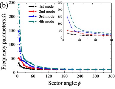
On the basis of verification of the presented method, next, the authors will study the influence of the stiffness ratio () and sector angle () on the vibration characteristics of orthotropic annular sector thin plates with classical boundary and elastically restrained conditions. Fig. 4 depicts the variations of the first four frequency parameters of orthotropic annular sector thin plates along the variations of the stiffness ratio with CCCC and E3E3E3E3 boundary conditions. From the Fig. 4, the frequency parameters decrease rapidly and may reach their crest around a critical stiffness ratio, and beyond this range, the frequency parameters almost remain unchanged. The variations of the first four frequency parameters of orthotropic annular sector thin plates relative to the sector angle are given in Fig. 5. It is evident that the variations of the vibration characteristics of the orthotropic annular sector thin plate have the similar tendency with the variations relative to the stiffness ratio.
Table 3Frequency parameters Ω for orthotropic annular sector plate with different classical boundary conditions
Boundary conditions | Methods | Mode number | |||||||
1 | 2 | 3 | 4 | 5 | 6 | 7 | 8 | ||
CCCC | Present | 88.838 | 89.265 | 90.381 | 92.702 | 96.820 | 103.30 | 112.55 | 124.76 |
FEM | 89.033 | 89.443 | 90.530 | 92.823 | 96.935 | 103.46 | 112.85 | 125.32 | |
SSSS | Present | 39.424 | 39.945 | 41.486 | 44.882 | 50.885 | 59.861 | 71.742 | 86.191 |
FEM | 39.457 | 39.971 | 41.504 | 44.905 | 50.941 | 60.012 | 72.072 | 86.798 | |
FFFF | Present | 2.3013 | 2.3519 | 5.5199 | 6.6522 | 10.370 | 13.819 | 16.791 | 24.197 |
FEM | 2.3014 | 2.3514 | 5.5231 | 6.6528 | 10.384 | 13.828 | 16.834 | 24.257 | |
CSCF | Present | 88.732 | 88.842 | 89.202 | 90.143 | 92.145 | 95.79 | 101.66 | 110.21 |
FEM | 88.930 | 89.029 | 89.365 | 90.270 | 92.234 | 95.85 | 101.74 | 110.37 | |
Table 4Frequency parameters Ω for orthotropic annular sector plate with various elastic boundary conditions
Boundary conditions | Methods | Mode number | |||||||
1 | 2 | 3 | 4 | 5 | 6 | 7 | 8 | ||
CE1CE1 | Present | 88.791 | 89.014 | 89.566 | 90.561 | 92.087 | 94.513 | 98.550 | 104.90 |
FEM | 88.990 | 89.199 | 89.733 | 90.700 | 92.176 | 94.540 | 98.542 | 104.91 | |
SE2SE2 | Present | 39.321 | 39.423 | 39.944 | 41.481 | 44.870 | 50.861 | 59.820 | 71.681 |
FEM | 39.356 | 39.455 | 39.971 | 41.499 | 44.891 | 50.916 | 59.971 | 72.010 | |
FE3FE3 | Present | 1.8326 | 4.7181 | 4.7284 | 8.5757 | 9.8222 | 12.718 | 15.337 | 17.275 |
FEM | 1.8327 | 4.7354 | 4.7400 | 8.6054 | 9.9099 | 12.785 | 15.489 | 17.384 | |
E2E1E2E1 | Present | 1.3032 | 4.8025 | 9.8634 | 15.543 | 21.385 | 27.578 | 34.504 | 36.093 |
FEM | 1.3037 | 4.8063 | 9.8763 | 15.567 | 21.422 | 27.642 | 34.611 | 36.077 | |
E3E2E3E2 | Present | 11.561 | 11.643 | 12.666 | 16.101 | 22.051 | 29.423 | 37.753 | 39.744 |
FEM | 11.553 | 11.707 | 12.739 | 16.172 | 22.141 | 29.555 | 37.958 | 39.747 | |
E1E3E1E3 | Present | 11.338 | 13.077 | 15.856 | 19.141 | 20.533 | 21.884 | 22.887 | 24.534 |
FEM | 11.284 | 13.045 | 15.850 | 19.164 | 20.427 | 21.868 | 22.921 | 24.759 | |
E1E1E1E1 | Present | 11.032 | 12.212 | 15.039 | 18.793 | 20.373 | 21.338 | 22.881 | 24.137 |
FEM | 10.975 | 12.168 | 15.015 | 18.793 | 20.261 | 21.259 | 22.913 | 24.234 | |
E2E2E2E2 | Present | 1.3226 | 5.0470 | 10.944 | 18.286 | 26.321 | 35.077 | 35.935 | 36.106 |
FEM | 1.3229 | 5.0506 | 10.960 | 18.328 | 26.408 | 35.239 | 35.942 | 36.135 | |
E3E3E3E3 | Present | 11.892 | 13.416 | 16.195 | 19.872 | 24.922 | 31.443 | 39.178 | 39.986 |
FEM | 11.830 | 13.376 | 16.204 | 19.932 | 25.019 | 31.583 | 39.368 | 39.950 | |
3.4. Orthotropic annular sector thin plates with line/arc supports
In the engineering practices, the plate structures are often restrained by internal line supports to reduce the magnitude of dynamic and static stresses and displacements of the structure or to satisfy special architectural and functional requirements. However, the research work on plates with internal line supports is scanty. Thus, in this paper, except the classical and general elastic boundary conditions, the authors also investigate the free vibration behaviors of orthotropic annular sector plates with internal radial line and circumferential arc supports. As shown in Fig. 4, the orthotropic annular sector plate is restrained by arbitrary internal radial line and circumferential arc supports. and represent the position of the th and th internal radial line and circumferential arc supports along the and directions, respectively. The displacement fields in the position of the line support satisfy 0 and 0. This condition can be readily obtained by introducing a group of continuously distributed linear springs at the location of each line/arc support and setting the stiffnesses of these springs equal to be infinite (which is represented by a very large number, 1014). Thus, the potential energy () stored in these springs is:
where and are the amount of circumferential arc supports and radial line in the and directions. and denote the corresponding circumferential arc supported and radial line springs distributed at and . By adding the potential energy stored in the line/arc supported springs in the Lagrangian energy function (Eq. (37)) and carrying out the Ritz procedure, the characteristic equation for a orthotropic annular sector thin plates with arbitrary boundary conditions and internal radial line and circumferential arc supports is readily obtained.
Fig. 4Variation of the frequency parameters Ω versus the stiffness rations (E1/E2) for annular sector plate: a) CCCC; b) E3E3E3E3
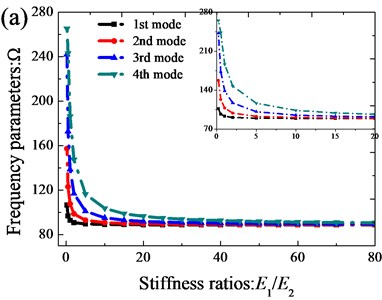
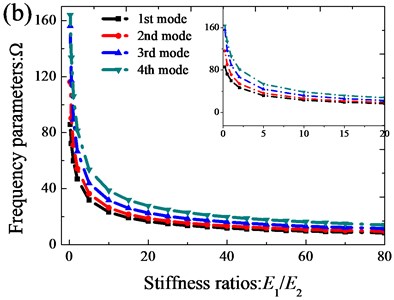
Fig. 5Variation of the frequency parameters Ω versus the sector angle for annular sector plate: a) CCCC; b) E3E3E3E3
In order to prove the validity of the present formulations for the vibration of orthotropic annular sector thin plates with internal radial line and circumferential arc supports, Table 5 presents the comparison of the first eight frequency parameters for sector plates with three classical boundary conditions, i.e. CCCC, SSSS, FFFF. For the purpose of stressing the effects of the line/arc supports, corresponding results for the considered annular sector plate without line/arc supports are also presented in the table. The benchmark results are provided by ABAQUS based on FEA method. From the table a consistent agreement of present results and referential date is seen. The discrepancy is very small and doesn’t exceed 0.61 % for the worst case. In addition, the table shows that the line/arc supports can increase the frequencies of the sector plate. Then, the influence of the locations of internal radial line and circumferential arc supports on the frequency of orthotropic annular sector plates is investigated. For simplicity of this research, when investigating the influence of the radial line support along direction, the circumferential edges of the plates are under clamped boundary conditions and we only change the radial boundary conditions; on the contrary, when studying the effect of the circumferential arc supports along direction, the radial edges are with clamped boundary condition and only the boundary conditions of the circumferential edges vary. In Fig. 7, the variations of the fundamental frequency parameters of the considered sector plate with against the radial line support location parameter and against the circumferential arc support location parameter are depicted. Six types of edge conditions used in the investigation are: C-C, S-S, F-C, C-F, F-S, S-F. It is obvious that the frequency parameters of the sector plate are significantly affected by the position of the radial line and circumferential arc support, and this effect varies with the edge conditions.
Fig. 6Schematic diagram of an annular sector plate with arbitrary internal radial line and circumferential supports
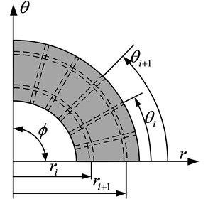
Table 5Comparison of the first eight frequency parameters Ω for orthotropic annular sector thin plate with different line supports
Line supports | Boundary conditions | Methods | Mode number | |||||||
1 | 2 | 3 | 4 | 5 | 6 | 7 | 8 | |||
None | CCCC | 20.453 | 20.552 | 20.809 | 21.343 | 22.291 | 23.783 | 25.913 | 28.724 | |
SSSS | 9.0767 | 9.1966 | 9.5514 | 10.333 | 11.715 | 13.782 | 16.517 | 19.844 | ||
FFFF | 0.5298 | 0.5415 | 1.2709 | 1.5316 | 2.3875 | 3.1816 | 3.8658 | 5.5709 | ||
CCCC | Present | 245.75 | 246.09 | 246.83 | 248.18 | 250.43 | 253.90 | 258.92 | 265.72 | |
FEM | 247.25 | 247.52 | 248.17 | 249.41 | 251.53 | 254.84 | 259.73 | 266.47 | ||
SSSS | Present | 157.85 | 158.20 | 158.99 | 160.50 | 163.08 | 167.11 | 172.92 | 180.65 | |
FEM | 158.40 | 158.73 | 159.46 | 160.90 | 163.41 | 167.38 | 173.17 | 180.95 | ||
FFFF | Present | 1.3847 | 2.6689 | 5.9102 | 11.2125 | 18.490 | 26.815 | 35.130 | 43.346 | |
FEM | 1.3822 | 2.6663 | 5.9101 | 11.2192 | 18.518 | 26.875 | 35.226 | 43.498 | ||
CCCC | Present | 246.09 | 246.26 | 248.18 | 248.97 | 253.90 | 256.03 | 265.72 | 270.00 | |
FEM | 247.52 | 247.68 | 249.41 | 250.17 | 254.84 | 256.85 | 266.47 | 270.36 | ||
SSSS | Present | 158.20 | 158.37 | 160.50 | 161.39 | 167.11 | 169.55 | 180.65 | 185.30 | |
FEM | 158.73 | 158.89 | 160.90 | 161.76 | 167.38 | 169.73 | 180.95 | 185.25 | ||
FFFF | Present | 2.6690 | 3.5863 | 11.212 | 14.306 | 26.815 | 30.980 | 43.346 | 47.782 | |
FEM | 2.6663 | 3.5829 | 11.219 | 14.304 | 26.875 | 30.992 | 43.498 | 47.812 | ||
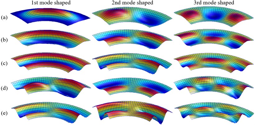
Since the vibration results for internal radial line and circumferential arc supported orthotropic annular sector thin plates with arbitrary boundary conditions are very limited in the literature, some new results are calculated here, which can be used for benchmark results by researchers as well as reference datum for practicing engineers. In Table 6, the first six frequency parameters of the considered orthotropic annular sector thin plate subjected to as many as nine possible boundary conditions are presented. And four different line/arc support conditions are considered in the calculation. In addition, the lowest four mode shapes for the sector plate with CE1CE1 boundary condition presented in Table 6 are given in Fig. 8. These view mode shapes are served to enhance our understanding of the vibratory characteristics of the orthotropic annular sector thin plates with internal radial line and circumferential arc supports.
Fig. 7Variation of the frequency parameters Ω versus the radial support locations and arc support locations for annular sector plate with different boundary conditions
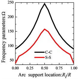
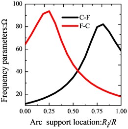
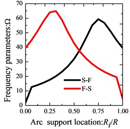
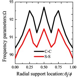
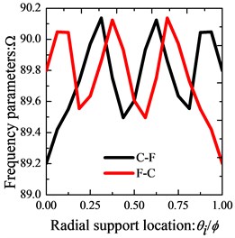
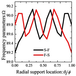
Fig. 8The lowest three modes shape for a CE1CE1 annular sector plate with various line supports: a) None; b) r1=R/2; c) r1=R/3, r2=2R/3; d) r1=R/2, θ1=ϕ/2; e) r1=R/3, θ1=ϕ/2, r2=2R/3
4. Conclusions
A modified Fourier-Ritz approach is presented for the free vibration analysis of orthotropic annular sector thin plates with general boundary conditions, internal radial line and circumferential arc supports. Under the current framework, the admissible displacement function of the plate, regardless of the boundary conditions, is expressed as a modified Fourier series, which is constructed as the linear superposition of a standard Fourier cosine series supplemented with auxiliary polynomial functions introduced to eliminate all the relevant discontinuities with the displacement and its derivatives at the edges and accelerate the convergence of series representations.
Table 6The first six frequency parameters Ω for orthotropic annular sector thin plates with different boundary conditions and various arc and radial line supports
Line supports | Mode | Boundary conditions | ||||||||
CE1CE1 | SE2SE2 | FE3FE3 | E2E1E2E1 | E3E2E3E2 | E1E3E1E3 | E1E1E1E1 | E2E2E2E2 | E3E3E3E3 | ||
1 | 245.70 | 157.75 | 3.9791 | 35.594 | 39.409 | 20.539 | 20.376 | 35.461 | 39.610 | |
2 | 245.88 | 157.85 | 8.1532 | 36.210 | 39.541 | 21.763 | 21.291 | 35.606 | 40.312 | |
3 | 246.21 | 158.20 | 12.735 | 37.691 | 40.215 | 23.898 | 23.511 | 36.347 | 41.593 | |
4 | 246.74 | 158.99 | 18.006 | 40.130 | 42.167 | 27.154 | 26.993 | 38.479 | 43.746 | |
5 | 247.60 | 160.49 | 24.718 | 43.639 | 46.157 | 32.158 | 31.553 | 42.773 | 47.563 | |
6 | 249.04 | 163.06 | 32.362 | 48.710 | 52.248 | 38.581 | 37.234 | 49.212 | 53.392 | |
1 | 454.35 | 355.14 | 71.101 | 115.53 | 117.55 | 75.70 | 75.66 | 115.47 | 117.63 | |
2 | 454.47 | 355.24 | 71.448 | 115.79 | 117.63 | 76.03 | 75.92 | 115.55 | 117.91 | |
3 | 454.72 | 355.56 | 72.082 | 116.31 | 117.95 | 76.64 | 76.52 | 115.87 | 118.40 | |
4 | 455.16 | 356.18 | 73.134 | 117.16 | 118.74 | 77.64 | 77.57 | 116.67 | 119.26 | |
5 | 455.87 | 357.23 | 74.895 | 118.48 | 120.29 | 79.34 | 79.17 | 118.24 | 120.80 | |
6 | 456.97 | 358.90 | 77.555 | 120.52 | 122.78 | 81.91 | 81.46 | 120.74 | 123.24 | |
1 | 245.88 | 157.85 | 8.1532 | 36.210 | 39.541 | 21.763 | 21.291 | 35.606 | 40.312 | |
2 | 245.94 | 157.89 | 10.185 | 36.694 | 39.664 | 22.614 | 22.070 | 35.743 | 40.779 | |
3 | 246.74 | 158.99 | 18.006 | 40.130 | 42.167 | 27.154 | 26.993 | 38.479 | 43.746 | |
4 | 247.00 | 159.43 | 21.022 | 41.583 | 43.696 | 29.301 | 29.013 | 40.134 | 45.253 | |
5 | 249.03 | 163.06 | 32.362 | 48.710 | 52.248 | 38.581 | 37.234 | 49.212 | 53.392 | |
6 | 249.88 | 164.62 | 36.274 | 51.791 | 55.762 | 42.035 | 40.395 | 52.880 | 56.802 | |
1 | 454.47 | 355.24 | 71.448 | 115.79 | 117.63 | 76.030 | 75.922 | 115.55 | 117.91 | |
2 | 454.50 | 355.26 | 71.657 | 115.92 | 117.67 | 76.228 | 76.095 | 115.59 | 118.04 | |
3 | 455.16 | 356.18 | 73.134 | 117.16 | 118.74 | 77.643 | 77.570 | 116.67 | 119.26 | |
4 | 455.31 | 356.42 | 73.818 | 117.63 | 119.26 | 78.300 | 78.205 | 117.20 | 119.80 | |
5 | 456.97 | 358.90 | 77.555 | 120.52 | 122.78 | 81.906 | 81.458 | 120.74 | 123.24 | |
6 | 457.49 | 359.74 | 79.145 | 121.74 | 124.22 | 83.437 | 82.829 | 122.20 | 124.67 | |
The general boundary conditions of the sector plate are accounted for by using the artificial spring boundary technique, in which the elastic restraint stiffnesses can take any value from zero to infinity to better simulate many real-world boundary conditions. Ritz procedure is used to obtain the exact solution based on the energy functions of those structures. The convergence of the present solution is checked and the excellent accuracy is validated by the comparison with the existing results published in the literature and FEM solutions. Excellent agreements are obtained from these comparisons. The effects of elastic restraint parameters and locations of radial line and circumferential arc supports are also investigated and reported. New results for free vibration of orthotropic annular sector thin plates with various edge conditions and internal radial line and circumferential arc supports are presented, which may be used for benchmarking of researchers in the field.
References
-
Onoe M. Contour vibrations of isotropic circular plates. Journal of the Acoustical Society of America, Vol. 28, Issue 6, 1956, p. 1158-1162.
-
Mcgee O. G., Leissa A. W., Huang C. S. Vibrations of completely free sectorial plates. Journal of Sound and Vibration, Vol. 164, Issue 3, 1993, p. 565-569.
-
Wang C. M., Thevendran V. Vibration analysis of annular plates with concentric supports using a variant of Rayleigh-Ritz method. Journal of Sound and Vibration, Vol. 163, Issue 1, 1993, p. 137-149.
-
Wang X., Striz A. G., Bert C. W. Free-vibration analysis of annular plates by the Dq-method. Journal of Sound and Vibration, Vol. 164, Issue 1, 1993, p. 173-175.
-
Wang X., Yang J., Xiao J. On free vibration analysis of circular annular plates with non-uniform thickness by the differential quadrature method. Journal of Sound and Vibration, Vol. 184, Issue 3, 1995, p. 547-551.
-
Wang X. W., Wang Y. L. Free vibration analyses of thin sector plates by the new version of differential quadrature method. Computer Methods in Applied Mechanics and Engineering, Vol. 193, Issues 36-38, 2004, p. 3957-3971.
-
Wang X. W., Wang Y. L. Re-analysis of free vibration of annular plates by the new version of differential quadrature method. Journal of Sound and Vibration, Vol. 278, Issue 3, 2004, p. 685-689.
-
Irie T., Yamada G., Ito F. Free-vibration of polar-orthotropic sector plates. Journal of Sound and Vibration, Vol. 67, Issue 1, 1979, p. 89-100.
-
Singh B., Hassan S. M. Transverse vibration of a circular plate with arbitrary thickness variation. International Journal of Mechanical Sciences, Vol. 40, Issue 11, 1998, p. 1089-1104.
-
Wong W. O., Yam L. H., Li Y. Y., Law L. Y., Chan K. T. Vibration analysis of annular plates using mode subtraction method. Journal of Sound and Vibration, Vol. 232, Issue 4, 2000, p. 807-822.
-
Houmat A. A sector Fourier p-element applied to free vibration analysis of sectorial plates. Journal of Sound and Vibration, Vol. 243, Issue 2, 2001, p. 269-282.
-
Chen J. T., Chen I. L., Chen K. H., Lee Y. T., Yeh Y. T. A meshless method for free vibration analysis of circular and rectangular clamped plates using radial basis function. Engineering Analysis with Boundary Elements, Vol. 28, Issue 5, 2004, p. 535-545.
-
Seok J., Tiersten H. F. Free vibrations of annular sector cantilever plates. Part 1: out-of-plane motion. Journal of Sound and Vibration, Vol. 271, Issue 3, 2004, p. 757-772.
-
Seok J., Tiersten H. F. Free vibrations of annular sector cantilever plates. Part 2: in-plane motion. Journal of Sound and Vibration, VVol. 271, Issue 3, 2004, p. 773-787.
-
Aghdam M. M., Mohammadi M., Erfanian V. Bending analysis of thin annular sector plates using extended Kantorovich method. Thin-Walled Structures, Vol. 45, Issue 12, 2007, p. 983-990.
-
Yongqiang L., Jian L. Free vibration analysis of circular and annular sectorial thin plates using curve strip Fourier p-element. Journal of Sound and Vibration, Vol. 305, Issue 3, 2007, p. 457-466.
-
Kim K., Yoo C. H. Analytical solution to flexural responses of annular sector thin-plates. Thin-Walled Structures, Vol. 48, Issue 12, 2010, p. 879-887.
-
Hajabasi M. A., Mirtalaie S. H. Free vibration analysis of functionally graded thin annular sector plates using the differential quadrature method. Proceedings of the Institution of Mechanical Engineers, Part C: Journal of Mechanical Engineering Science, Vol. 225, Issue 3, 2011, p. 568-583.
-
Liew K. M., Kitipornchai S., Xiang Y. Vibration of annular sector mindlin plates with internal radial line and circumferential arc supports. Journal of Sound and Vibration, Vol. 183, Issue 3, 1995, p. 401-419.
-
Li W. L. Free vibrations of beams with general boundary conditions. Journal of Sound and Vibration, Vol. 237, Issue 4, 2000, p. 709-725.
-
Li W. L. Comparison of Fourier sine and cosine series expansions for beams with arbitrary boundary conditions. Journal of Sound and Vibration, Vol. 255, Issue 1, 2002, p. 185-194.
-
Du J., Li W. L., Jin G., Yang T., Liu Z. An analytical method for the in-plane vibration analysis of rectangular plates with elastically restrained edges. Journal of Sound and Vibration, Vol. 306, Issues 3-5, 2007, p. 908-927.
-
Du J. T., Liu Z. Li W. L., Zhang X., Li W. Free in-plane vibration analysis of rectangular plates with elastically point-supported edges. Journal of Vibration and Acoustics-Transactions of the ASME, Vol. 132, Issue 3, 2010, p. 031002.
-
Shi D., Wang Q., Shi X., Pang F. A series solution for the in-plane vibration analysis of orthotropic rectangular plates with non-uniform elastic boundary constraints and internal line supports. Archive of Applied Mechanics, Vol. 85, Issue 1, 2015, p. 51-73.
-
Shi X., Shi D., Li W., Wang Q. A unified method for free vibration analysis of circular, annular and sector plates with arbitrary boundary conditions. Journal of Vibration and Control, 2014.
-
Jin G., Ye T., Chen Y., Su Z., Yan Y. An exact solution for the free vibration analysis of laminated composite cylindrical shells with general elastic boundary conditions. Composite Structures, Vol. 106, 2013, p. 114-127.
-
Jin G., Ye T., Ma X., Chen Y., Su Z., Xie X. A unified approach for the vibration analysis of moderately thick composite laminated cylindrical shells with arbitrary boundary conditions. International Journal of Mechanical Sciences, Vol. 75, 2013, p. 357-376.
-
Chen Y., Jin G., Liu Z. Flexural and in-plane vibration analysis of elastically restrained thin rectangular plate with cutout using Chebyshev-Lagrangian method. International Journal of Mechanical Sciences, Vol. 89, 2014, p. 264-278.
-
Jin G., Ma X., Shi S., Ye T., Liu Z. A modified Fourier series solution for vibration analysis of truncated conical shells with general boundary conditions. Applied Acoustics, Vol. 85, 2014, p. 82-96.
-
Jin G., Ye T., Jia X., Gao S. A general Fourier solution for the vibration analysis of composite laminated structure elements of revolution with general elastic restraints. Composite Structures, Vol. 109, 2014, p. 150-168.
About this article

The authors gratefully acknowledge the financial support from the National Natural Science Foundation of China (No. 51209052), Heilongjiang Province Youth Science Fund Project (No. QC2011C013) and Harbin Science and Technology Development Innovation Foundation of Youth (No. 2011RFQXG021).
