Abstract
This paper investigates the performance of the synthetic aperture focusing technique (SAFT) on ultrasonic imaging of concrete block. A 2D model is established to simulate the obstacle inside the concrete block by finite-difference time domain (FDTD) method. In order to better meet the directivity of ultrasonic sensor transmitting, the mobile perfectly matched layer (PML) absorbing boundary is used in this paper. Comparing with the experiment result in an artificial concrete specimen (70 cm (L) × 60 cm (W) × 60 cm (H)), the simulation result has good accordance, which proves the effectiveness of the proposed method.
1. Introduction
Concrete is a common building material and is widely used in bridges, dams, and other buildings. Due to aging and wear of concrete, the degradation may occur during the life cycle of concrete [1-2]. Considering the importance of concrete to people’s life safety, the health condition of concrete has attracted more and more attentions in recent years [3-7].
In order to evaluate the condition of concrete, a lot of non-destructive testing methods, such as Impact-Echo (IE), vibration testing and ultrasonic tomography, have been applied in many fields [8]. Because of the heavy attenuation and multi-path reflections of the ultrasonic wave propagating in concrete, the interpretation is not possible with single point measurement (A-scan) but requires the combination of several measuring points (B-scan or C-scan). With unprocessed measurement data, the resolution of ultrasonic imaging is still limited by B-scan or C-scan. In order to improve the resolution of ultrasonic imaging, Spies. M [9] reported the SAFT method in imaging of defects in composite material. Schickert [10] reviewed the progress in ultrasonic imaging of concrete with emphasis on linear array SAFT method. A. O. De la Haza [11] introduced their Mira and Eyecon ultrasonic imaging system based on SAFT in 2013.
Although some achievements had been obtained using the above methods, the reflection mechanism of concrete is still not clear, and the effect of some complicated factors is still need to be investigated, such as the diffusion angle, the waveform and the frequency of the transmitting signal, the target size, and the material characteristic. To observe the influence of these factors, numerical simulation is required. L. Satyanarayan [12] reported the simulation of phased array ultrasonic wave detection for imaging and sizing crack-like defects in mild-steel pipe using the finite-difference time domain (FDTD) method. Abhijit G. [13] investigates the influence of air void inside the concrete medium using FDTD method with PML absorbing boundary condition, but the diffusion angel was not considered in his research.
In this paper, we proposed the mobile PML absorbing boundary method to simulate the diffusion angel of ultrasonic sensor. As described in [13], the scattered wave field is generated by simulating acoustic wave propagation using the FDTD method. By transmitting and receiving alone a line, a set of ultrasonic data can be obtained. These data are processed by SAFT method and the cross-section of the concrete block can be displayed. In order to validate the effectiveness of the proposed method, we compare with the experiment result in an artificial concrete specimen (70 cm (L) × 60 cm (W) × 60 cm (H)), which shows the proposed method has good accordance.
The rest of paper is organized as follow: section 2 introduces the mobile PML absorbing boundary; section 3 designs the simulation experiment and analyzes the result; section 4 concludes the paper.
2. Acoustic wave equation discretization with mobile PML absorbing boundary
For simplicity, a 2D model is analysed using the FDTD method in homogeneous isostropic material. The 2D acoustic wave equation with a transmitting source can be given by:
where is divided into × grid, is the sound velocity, is the wave displacement, and is a transmitting source.
The control equation of Eq. (1) with PML absorbing boundary condition can be expressed as [14]:
where is the attenuation factor.
Perfectly matched layer absorbing boundary condition can be thought as an extra set of layers around the computational domain, which rapidly decay the acoustic wave propagating in the lossy layers. Considering the reflection will still arise as the enormous contrast of the attenuation factor, the attenuation factors are increased gradually in the lossy layers, which can be expressed as:
where and is the attenuation factor in direction and direction, respectively. is the amplitude factor, and is the thickness of the lossy layer. In our practical experiment, a pair of ultrasonic sensor is used along a line on the surface of the concrete block. Fig. 1 shows the operation principle of ultrasonic imaging system. The scanning direction is from A to B.
Fig. 1The operation principle of ultrasonic imaging system
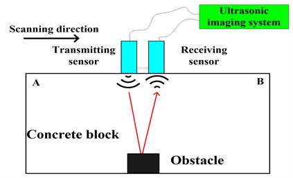
According to the directivity characteristic of ultrasonic sensor, the mobile PML absorbing boundary is proposed. In the simulation, two bugle-like banded absorbing layers are added and follow the transmitting point at each move. Considering the reflection from the bottom of the concrete block in practical experiment, we delete the lossy layer at the bottom in the simulation. The distribution of the attenuation factor with the mobile PML absorbing boundary is shown in Fig. 2.
Fig. 2The distribution of attenuation factors with the mobile PML absorbing boundary
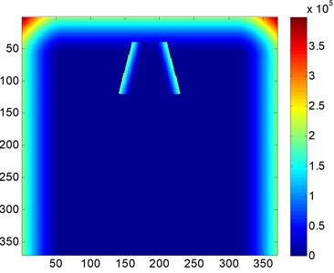
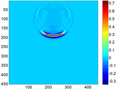
Fig. 3The snapshot of acoustic wave propagation
In the standard central FDTD method, all second derivatives in Eq. (1) are approximated by the second-order central difference formulas. The discretization formulas of Eq. (1) can be written as:
where is the time step. and are the spatial grid size in direction and direction, respectively. The displacement field updates as the time marches on. Fig. 3 is the snapshot of acoustic wave propagation.
3. Simulation result
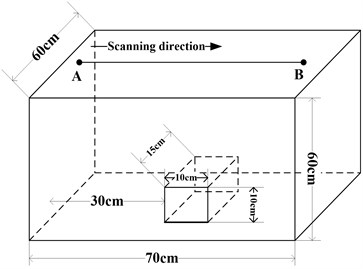
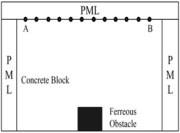
According to the size of the artificial concrete block specimen, a 2D model is established in the simulation. Fig. 4 shows the configuration and the cross-section of the tested concrete specimen. The specimen is 70 cm (L) × 60 cm (W) × 60 cm (H) with a ferreous obstacle inside it.
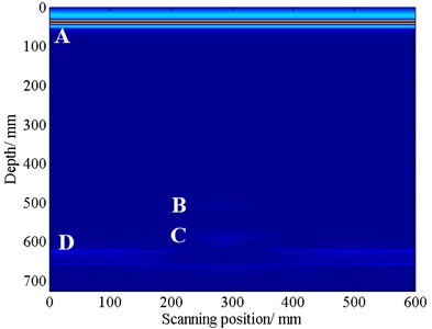
The sound velocity in concrete media is 3.8 km/s through pitch-catch method, and the sound velocity in ferreous media is 6.0 km/s. The transmitting source is located at the surface of the concrete block and its expression is , where 50 kHz. Time support for the simulation is 4.21×10⁻⁴ s. Uniform spatial grids are used and the spatial grid size is 0.004 m. Due to the limitation of the CFL condition, the time step is 4.24×10⁻⁷ s. Fig. 5 shows the results of the SAFT imaging.
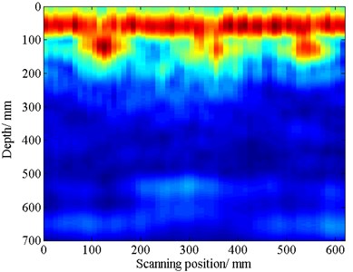
In Fig. 5(a), the reflections can be displayed clearly, which marks A, B, C and D. Part A is the direct wave form the transmitting sensor to the receiving sensor; Part B is the reflection form the surface of the ferreous obstacle; Part C is the reflection form the bottom of the ferreous obstacle; and part D is the reflection form the bottom of the concrete block. In Fig. 5(b), the imaging result is affected by unwanted noise. But there is a prominent bright block at position (300 mm, 500 mm), which can be though as the reflection from the ferreous obstacle. From Fig. 5(a) and (b), we can both find the ferreous obstacle at position (300 mm, 500 mm), which is similar to the configuration of the tested concrete specimen.
Fig. 4a) The configuration of the tested concrete specimen; b) the cross-section of the tested concrete specimen
a)
b)
Fig. 5a) The SAFT imaging result using simulation data; b) The SAFT imaging result using experimental data
a)
b)
4. Conclusion
In this paper, a mobile PML absorbing boundary is proposed to simulate the diffusion angle in ultrasonic transmitting. A 2D model corresponding to the artificial concrete block specimen is established, and a set of data is obtained. By comparing the SAFT imaging results between simulation data and experimental data, the simulation result has good accordance with the experimental result, which proves the effectiveness of the proposed method.
References
-
John S. P., Joseph L. R. A survey of developments in ultrasonic NDE of concrete. IEEE Transactions on Ultrasonic, Ferroelectrics, and Frequency Control, Vol. 41, Issue 1, 2001, p. 140-143.
-
Naffa S. O., Goueygou M., Piwakowski B., BuyleBodin F. Detection of chemical damage in concrete using ultrasound. Ultrasonic, Vol. 40, 2002, p. 247-251.
-
Chaix J. F., Garnier V., Corneloup G. Concrete damage evolution analysis by backscattered ultrasonic waves. NDT&E International, Vol. 36, 2003, p. 461-469.
-
Nihat M. B., Uthai B. Enhanced ultrasonic imaging with split-spectrum processing and polarity thresholding. IEEE Transactions on Acoustics, Speech and Signal Processing, Vol. 37, 1989, p. 1590-1592.
-
Shao Z. X., Shi L. H., Cai J. Wavelet modeling of signals for non-destructive testing of concretes. Measurement Science and Technology, Vol. 22, 2011, p. 1-8.
-
Philippidis T. P., Aggelis D. G. Experimental study of wave dispersion and attenuation in concrete. Ultrasonics, Vol. 43, 2005, p. 584-595.
-
Abdelrahman M., Eibatanouny M. K., Ziehl P. H. Acoustic emission based damage assessment method for prestressed concrete structures: modified index of damage. Engineering Structures, Vol. 60, 2014, p. 258-264.
-
McCann D. M., Forde M. C. Review of NDT methods in the assessment of concrete and masonry structures. NDT&E International, Vol. 34, 2001, p. 71-78.
-
Spies M., Rieder H., Dillhofer A., Schmitz V., Muller W. Synthetic aperture focusing and time-of-flight diffraction ultrasonic imaging-past and present. Journal of Nondestruct Evaluation, Vol. 31, 2012, p. 310-323.
-
Schickert M. Progress in ultrasonic imaging of concrete. Materials and Structures, Vol. 38, 2005, p. 807-815.
-
De la Haza A. O., Samokrutov A. A., Samokrutov P. A. Assessment of concrete structures using the Mira and Eyecon ultrasonic shear wave devices and the SAFT C image reconstruction technique. Construction and Building Materials, Vol. 38, 2013, p. 1276-1291.
-
Satyanarayan L., Sridhar C., Krishnamurthy C. V., Balasubramaniam K. Simulation of ultrasonic phased array technique for imaging and sizing of defects using longitudinal waves. International Journal of Pressure Vessels and Piping, Vol. 84, 2007, p. 716-729.
-
Abhijit G., Carey M. R., David A., Sara W. F. Synthetic aperture imaging for flaw detection in a concrete medium. NDT&E International, Vol. 45, 2012, p. 79-90.
-
Wang W. H., Ke X., Pei J. Y. Application investigation of perfectly matched layer absorbing boundary condition. Progress in Geophysics, Vol. 25, Issue 5, 2013, p. 2508-2514, (in Chinese).
