Abstract
As the certain gear transmission system becomes more complex and precise, the flexibility of shaft will influence the dynamic response of system. Build the rigid model of gear system and the finite element model of the gear shaft. Establish the rigid-flex coupling model with the virtual prototype technology, simulation and make a contrast between rigid model and rigid-flex model. Find the influence of shaft flexibility on the dynamic response of gear system, which can enhance the accuracy rating of the model. With the increase of the bearing interval, the impact of coupling will become severely. Furthermore, we analysis the influencing factor of the fatigue life of the shaft. Analysis the law of the fatigue life in the different , the result can provide a reference for the optimum structural design of the gear transmission system.
1. Introduction
Gear transmission system is a complex structure system including gear pair, drive shaft, gear wheel, bearing and so on. This kind of structure is different from that of a simple rotating system. In recent years, many researchers have done a lot of research and experiments on the dynamic characteristics of gear rotor system. The research contents are involved in the dynamic modeling [1-3], the inherent characteristics [4], the dynamic response [5], the vibration noise suppression [6, 7], and so on. Among them, the dynamic modeling and the inherent characteristic analysis are the basis of the study of the dynamic performance and the reduction of the vibration and noise.
According to the different modeling methods, we can divide the gear transmission model into three kinds: centralized parameter model, finite element model and rigid-flex coupling model [8-11]. Among them, lumped parameter model is widely used because it is simple and easy to be solved. In the traditional multi-body dynamics theory, kinematic constraints are often used in the establishment of a variety of models, which is considered as an ideal, so that the influence of the gap, flexibility and various nonlinear factors are neglected. With the development of modern mechanism, such as industrial robot, national defense automation equipment and aerospace mechanism are changing day by day, the effect on the dynamic performance and motion precision of the mechanism is not neglected.
At present, the method for treating the elastic rotor is usually use a system which is composed of a number of moments of inertia, and is coupled with the torsion vibration model of the gear system. This method takes into account the coupling effect between the gears and the rotor. But in the process of the discrete and the equivalent, the model is more flexible. With the aid of virtual prototype modeling, the model can be easily realized, and can be extended to complex multilevel gear transmission system. The load information of specific parts can be obtained by simulation.
In the view of the above problems. In this paper, we establish the rigid-flex coupling dynamic model of multistage gear transmission system and carry out the research of wear of bearing influence on system operation, and in the dynamic response analysis of the gear transmission system, this paper fully considered the nonlinear factors in the system. On the basis of this, the fatigue life of the transmission shaft is further analyzed, which lays the foundation for the next research.
2. Theory model of the gear system
The multi-stage gear system as shown in the Fig. 1, in order to make the analysis without loss of generality, we set the three gear axes not on the same straight line, the intermediate shaft and output axis connection to the positive direction, vertical in the direction of the intermediate shaft and output axis connection to a positive direction and counter clockwise direction to rotate in a positive direction, establish corresponding coordinate system, nonlinear dynamics of the system model, such as shown in Figure 1, in dynamics analysis for the problem is simplified to facilitate the study of nonlinearity system, do the following assumptions:
1) The system’s bearings are fixed support, and the gear box body also is fixed support;
2) The gear and bearing are rigid body, ignore the gear and bearing’s elastic;
3) Considering only the elastic of gear shaft, regardless of tooth contact friction and the friction between bearing and shaft;
4) Make the assumption that the meshing line direction is constant.
Fig. 1The structure of multistage gear system
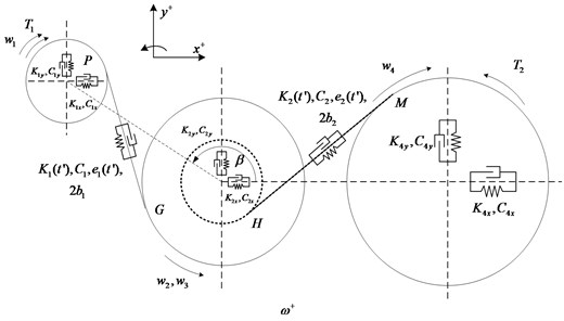
As shown in the gear system structure figure, , , , are the multistage gear system’s bearing stiffness and damping of the gear pair; , , , are the time-varying meshing stiffness, mesh damping, transmission error and the interval between the tooth; is the angular velocity of each gear; , is the input torque and the load torque; is the angle between the direction of the first line and a horizontal center of gear pair. The dynamic model is a two-dimensional plane vibration system, the gear 2, 3 has the same translational and rotational degree of freedom. Therefore, the model has 9 degrees of freedom, for the three gear shaft center along the direction of translational freedom degrees and around the respective axis rotational degrees of freedom, they are expressed as , , , , , , , , , introduced into the mesh points , along the meshing line direction relative displacement is , relative displacement of meshing point , along the contact line is , then the gear pair meshing force nonlinear function can be expressed as:
where is the mesh force of gear pair along the meshing line and the , is the time-varying mesh stiffness with ; is the function of gear interval with ; is the gear transmission error with ; is the gear’s radius with ; is the mesh angle of gear.
3. Building the simulation model of the system
3.1. Rigid-flex coupling model
3.1.1. Build the flex shaft
Because of the complex structure of the drive shaft, the structure model of the gear transmission system is reduced, and the error is reduced. In the finite element analysis software MSC.Patran, the model can be built into the finite element analysis software.
Fig. 2The finite model of gear shaft
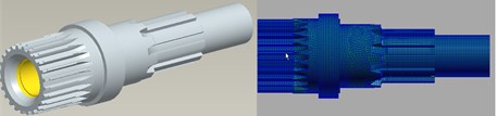
Interface point is set at the ends of the drive shaft and the bearing center position. Through the REB2 rigid beam element, the Interface points are connected with the contact surface of the gear shaft.
Fig. 3Stress envelope of drive shaft
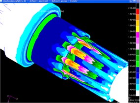
From the results of calculation and analysis, it can be seen that the dangerous part of the component is connected with the spline connection of the driving shaft.
3.1.2. Modal analysis
The modal analysis of the gear shaft is carried out, and the first six order mode is the rigid body mode of the gear shaft, which we can ignore them in this paper. The first 18 order modes are obtained from the beginning of the seventh order.
Table 1Modal frequency of flexible rotor
Mode | Frequency (Hz) | Mode | Frequency (Hz) | Mode | Frequency (Hz) |
7 | 2792.2 | 10 | 6878.8 | 13 | 11322.1 |
8 | 2818.2 | 11 | 6951.6 | 14 | 11493.7 |
9 | 6567.8 | 12 | 11235.8 | 15 | 11536.9 |
It can be seen that the low order mode is the low order mode of the first 12 order fixed interface mode and the constrained mode synthesis. High order modes are the free vibration modes of the free boundary, which is the fixed interface constraint mode. In the middle of higher order modes and low order modes, a narrow transition region can be ensured in the premise of ensuring the accuracy of the low order modes and all boundary constraints. Although the constrained modal frequency is very high, it cannot be abandoned, and the constraint mode is equivalent to the corresponding constraint.
We can get the modal neutral files (.MNF file) from the modal analysis of the drive shaft, lead these files into the gear transmission system of rigid model, replaced the previous rigid drive shaft, definition of drive shaft and gear to the connection is rigid connection, so that we establish the rigid-flex coupling gear transmission system.
3.2. Simulation and analysis
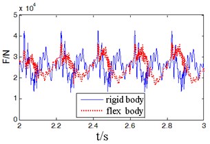
3.2.1. Analysis on the meshing force
Through figure 4, by the rigid and flexible gear meshing force contrast, we can see that when considering the flexible function of the drive shaft, because the impact energy of the gear meshing in and out were absorbed by the flexibility of the drive shaft, the meshing force vibration peak reduced by 14 %, compared with the rigid body model the result is more in line with the actual situation. In addition, in the calculation of the meshing force, considering the flexible rotor can significantly reduce the meshing force peak, reducing unnecessary redundancy when design the lightweight for the system.
Fig. 4Force contrast of gear meshing
3.2.2. Simulation and analysis on the wear of bearing
In order to analysis the condition of the system, we set the bearing interval as 0 mm and 0.3 mm, the Y-force of the bearing is shown as figure 5.
Fig. 5Y-force curve of bearing
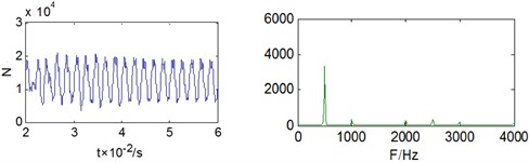
a) Theory value (0 mm)
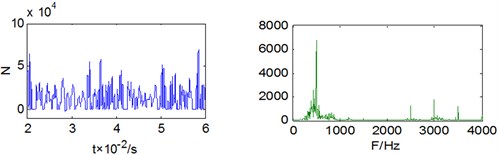
b) Big interval (0.3 mm)
From the figure 5 we can find that when the interval is 0, the basic frequency of the stress on the bearing is the meshing frequency with some double frequency. When the interval of bearing is bigger, the couple effects between gear, flexible shaft and bearing will enhance and the vibration amplitude of the bearing stress will increase obviously, the stress frequency will be continuous spectrum in low frequency, there will be sideband in fundamental frequency and double frequency, and the energy of high-order multiplier will increase.
4. Analysis on the influencing factor of the drive shaft fatigue life
According to the inquiry, the most important factor that influence the fatigue life of drive shaft is the ratio of inner diameter and external diameter () and the stress on the root segment of the spline. Next work is to analysis the different influence effect on the fatigue life of drive shaft under various . On the basis of dynamic simulation analysis, we will combine the fatigue analysis theory under random loading and the virtual prototype technology together to analysis the fatigue life of drive shaft. Furthermore, we analysis the stress of component on the transmission system, find a systematic method which can be applied to the transmission system’s fatigue life analysis and structure improvement.
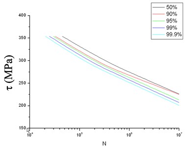
4.1. The P-S-N curve of material
From the finite element analysis and dynamic simulation, we can find that the most load are in the below of endurance limit , in order to calculate the damage of cyclic stress which below the endurance limit, we must analysis the P-S-N curve of material.
In the transmission system we analysis, the shaft and gear are mostly made of 20Cr2Ni4A, the strength characteristics are shown as Table 2:
Table 2Static strength character of 20Cr2Ni4A
Shear yield Intensity () | Strength of extension () | Ductility () | Percentage reduction of area () | Elasticity modulus () | Poisson ratio () |
1363 MPa | 1483 MPa | 10 % | 45 % | 2.07e5 MPa | 0.29 |
The figure 6 shows the fatigue life curves in different reliability.
Fig. 6Torsion fatigue’s P-S-N curve of 20Cr2Ni4A
4.2. Influence factor analysis on fatigue life of drive shaft
Keep the as fixed, the different will influence the fatigue life of drive shaft as Table 3.
Table 3Fatigue life of drive shaft on different d/D as fixed D
0.35 | 0.40 | 0.44 | 0.48 | |
Fatigue life (km) | 105000 | 92530 | 65760 | 13500 |
Weight of shaft (kg) | 31.5 | 30.1 | 29.6 | 26.2 |
Keep the as fixed, the different will influence the fatigue life of drive shaft as Table 4.
Table 4Fatigue life of drive shaft on different d/D as fixed d
0.35 | 0.40 | 0.44 | 0.48 | |
Fatigue life (km) | 105000 | 50880 | 25760 | 6890 |
Weight of shaft (kg) | 31.5 | 23.8 | 21.6 | 19.8 |
From the results above, we can find that the different values of have an enormous implications on fatigue life and weight of drive shaft, the detailed result is:
When decrease the external diameter of drive shaft, there will be an enormous implication on the fatigue life and weight of drive shaft, when the diameter of shaft decrease about 10 %, the weight will have a 15 % reduction and the fatigue life will decrease about 50 %. However, the influence on weight and fatigue life of drive shaft is not obviously when decrease the inner diameter : when the value increase 10 %, the weight will decrease about 5 % and the fatigue life will decrease 10 %.
5. Conclusion
This paper establish the rigid-flex coupling model of a certain gear transmission system, which will reflect the physical truth of the transmission system by concerning the deformable features of the drive shaft. On the basis of the rigid-flex coupling model, simulation the abrade of the bearing and analysis the relationship between the attrition and the stress on the bearing. Analysis the system performance in different values of interval, establish the foundation of fault diagnosis and prognosis of drive shaft. On the basis of dynamic simulation, we analysis the factors that influence the fatigue life of drive shaft, which have a guiding significance on the optimum structural design of drive shaft.
References
-
Hall J. F., Mecklenborg C. A., Chen D. M., et al. Wind energy conversion with a variable – ratio gearbox: design and analysis. Renewable Energy, Vol. 36, Issue 3, 2011, p. 1075-1080.
-
Sun Yuehai, Zhang Ce, Pan Fengzhang Dynamic model of a spur gear transmission system vibration. Chinese Journal of Mechanical Engineering, Vol. 36, Issue 8, 2000, p. 47-50.
-
Xia Boqian, Yu Lie, Xie Youbo Dynamics analysis of geared rotor-bearing system of DH type turbine compressor. Journal of Vibration Engineering, Vol. 16, Issue 2, 2003, p. 251-225.
-
Parker R. G., Vijayakar S. M., Imajo T. Non-linear dynamic response of a spur gear pair: modelling and experimental comparisons. Journal of Sound and Vibration, Vol. 237, Issue 3, 2000, p. 435-455.
-
Zhang Q., Jiang G. M., et al. Design of flexible electronic shogging system for high-speed warp-knitting machine. Journal of Donghua University (Eng. Ed.), Vol. 30, Issue 3, 2013, p. 202-206.
-
Li Ming, Hu Haiyan Steady state response of the coupled lateral-torsional vibrations of geared rotor system under a holonomic constraint. Journal of Vibration Engineering, Vol. 16, Issue 1, 2003, p. 79-84.
-
Li M. F., Lim T. C., Shepard W. S. Modeling active vibration control of a geared rotor system. Smart Materials and Structures, Vol. 13, Issue 3, 2004, p. 449-458.
-
Xu L. X., Li Y. G., et al. Effects of bearing clearance and flexibility on the dynamic errors of mechanisms. Chinese Journal of Mechanical Engineering, Vol. 48, Issue 7, 2012, p. 30-36.
-
Wang Q. M., Li H., Yao J. Dynamics simulation of the gearbox transmission system based on ADAMS. Mechanical Transmission, Vol. 37, Issue 6, 2013, p. 75-77, (in Chinese).
-
Zhang J. W., Liu Y. Q. Research on simulation and test of the nonlinear responses for the hydraulic shock absorber. Journal of Donghua University (Eng. Ed.), Vol. 20, Issue 4, 2003, p. 98-102.
-
Cheng Z., Hu N. Q., Gao J. W. Prognosis of fatigue crack in planetary gear sets based on physical model and modified gray theory. Journal of Mechanical Engineering, Vol. 47, Issue 9, 2011, p. 79-84, (in Chinese).
-
Heege A., Betran J., Radoveic Y. Fatigue load computation of wind turbine gearboxes by coupled finite element, multi-body system and aerodynamic analysis. Wind Energy, Vol. 10, Issue 5, 2007, p. 395-413.
About this article

