Abstract
Resonance is a phenomenon of utmost importance in railways engineering, leading to vast damages both in track and vehicles. Thus, to avoid the undesired effect of resonance, it must be studied, understood and predicted. To this aim, in the current study a FE model able to reproduce the dynamic behavior of a real stretch of track has been developed and its correct behavior has been calibrated with real data. Furthermore, different measures of mitigation have been proposed and its effect on displacements and vibrations in the mid-span section of a railway bridge have been evaluated.
1. Introduction
The dynamic response of a track subjected to the passage of a train is a complex phenomenon, whose understanding is of utmost importance to maximize track quality, minimize its maintenance needs and to assure its safety. The importance of the dynamic response of the track is even higher when it is built over a railway bridge, since resonance conditions may be reached.
The phenomenon of resonance takes place when frequencies similar to the eigenfrequencies of the bridge are induced by the passage of the train. These frequencies may be associated to the distance between adjacent wheelsets, the distance between adjacent sleepers or irregularities in the wheel-rail contact among others.
Under these circumstances, the vibratory response of a track is highly increased, thus enhancing the risk of damage to the structure and, sometimes, leading to its collapse. These reasons have encouraged the study of resonance in railway bridges over the last few decades. Some authors as [1] and [2] studied the effect of high-speed trains on bridges and the procedures to calculate the dynamical response of the bridge under resonance conditions.
The dynamic response of a railway bridge is influenced by numerous factors, such as structure natural frequencies and damping, train speed or the length of both the structure and the train. Within this context, [3] studied the influence of different parameters, including the bridge-to-carriage length ratio. [4] demonstrated that the primary frequencies in the bridge response might be caused by the driving frequencies, which are related to the time the train spent crossing the bridge, and the dominant frequencies, which are caused by the repeated loads.
Among the studies found along the literature, it may be said that there are different ways to calculate he dynamic response of a bridge under dynamic excitations. The bridge has been modeled from simple beams [5, 6] to complex FEM models with hundreds of DOF. Meanwhile, the effect of the train also presents different procedures to be simulated. The main methods are the moving loads [7-9], the moving mass [10-12], and the moving sprung mass models [5, 13, 14].
The present paper aims to assess the dynamic response of a real short-span bridge, whose dominant frequencies are excited by the passage of a train. This study has been performed by means of a detailed 3D FEM model, calibrated and validated with accelerations data from a gathering campaign. Then, the effect of the train over the bridge in several scenarios has been simulated following the moving loads procedure and, finally, conclusions have been drawn.
2. Methodology
In the present section, the methodology followed to evaluate the dynamic behavior of a bridge has been presented: first of all, the numerical FE model developed to simulate the bridge has been detailed. Then, to assess the validity of the model and the accurateness of the results, the vibrational data recorded in a real track have been compared to the accelerations calculated by the model; and finally, a modal analysis has been performed to calculate the flexural modes of the bridge.
Once bridge modes of vibration are known, the frequencies associated to these modes have been induced by a set of loads travelling through the stretch – simulating the passage of the wheelsets, so as to evaluate the behavior of the track under resonance conditions. Moreover, different scenarios including ballast improvements, variations on damping and changes on railpads and sleepers have been evaluated.
2.1. FE model
To simulate the behavior of the bridge and the track a FE model has been implemented by means of the commercial software ANSYS LS-DYNA V14, following the research carried out by [15].
As depicted in Fig. 1, the model consists on a ballasted track, provided with wooden sleepers and UIC-45 rails, built over a short-span bridge. The whole structure is modeled as a mesh of hexahedral elements, whose maximum size depends on the maximum wavelength transmitted through the track and the minimum size is set considering the computational time. Thus, following [15]. The maximum size of the elements has been set to 0.25 m.
Fig. 1Track model of the bridge
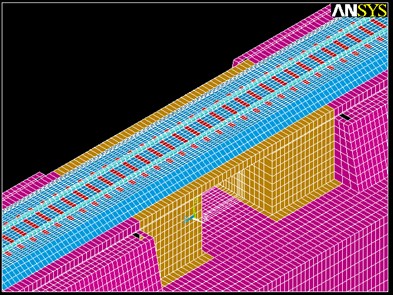
It has been proved that, in this case, the dynamic wave generated by the passage of a train does not induce large strains in the soil. Thus, displacements on the system are limited to the elastic range in the stress-strain diagram, as stated by [15], and this leads to the assumption that materials’ behavior is linear elastic. Following this hypothesis, the mechanical parameters assigned to each element of the model are presented in Table 1.
Results for displacements, velocities and accelerations are obtained by means of Lagrange equation, being the motion in each node calculated as follows Eq. (1):
Being the mass matrix, the damping matrix, the stiffness matrix, the displacement vector, the velocity vector, the acceleration vector and the external forces vector.
Regarding track excitation, in this case the moving loads method is considered. Furthermore, since a linear behavior for the materials is assumed, the superposition principle may be applied so as to calculate the vibration response induced by the train. Thus, following studies carried out by authors as [16] or [15], track response due to the passage of a wheelset is calculated and then extended in time, considering train axles distribution and vehicle speed.
Once the FE model is properly implemented, calibration and validation stage may be started.
Table 1Materials mechanical properties
(MPa) | (kg/m3) | ||
Rail | 210,000 | 0.3 | 7850 |
Railpad | 600 | 0.3 | 7850 |
Sleeper | 1310 | 0.35 | 700 |
Ballast | 80* | 0.2 | 1900 |
Concrete slab | 27500 | 0.225 | 2350 |
Soil | 200* | 0.3 | 1890 |
*Parameter subjected to calibration | |||
2.2. Calibration and validation
The main goals of this calibration and validation stage are, on the one hand, to obtain the unknown parameters needed to implement the model; in the present case, these parameters are ballast and soil elasticity modulus as well as damping coefficient. On the other hand, this stage is necessary to assess the correct behavior of the model. With this aim, data recorded in a gathering campaign are divided in two sets: a part of them are used to calibrate the unknown parameters of the model and then, the other part, to validate it. Therefore, the calibration has been performed from the accelerations registered in the sleepers, while the accelerations recorded in the rail web have been used to validate the model.
It must be noted that, among the several registers recorded in the gathering campaign, those accelerograms considered representative were the ones selected to calibrate and validate the model.
The gathering campaign was carried out near Xativa (Spain), in a simple ballasted track that belongs to a mid-distance network. In this track, UIC-45 rails are placed over wooden sleepers and, between them, steel railpads may be found. Below the sleepers, a 45 cm ballast layer rests over a 5 m long bridge, which is composed of a 40 cm thick reinforced concrete slab.
Fig. 2Gathering campaign
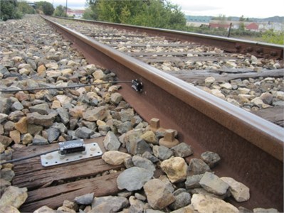
The studied stretch was instrumented as presented in Fig. 2, placing accelerometers both on the rail web (accelerometer 1) and on the sleeper (accelerometer 2). The devices used to this aim where SEQUOIA FAST TRACER accelerometers, whose main characteristics are shown in Table 2.
Table 2Main SEQUOIA FAST TRACER accelerometers characteristics
Rail | Sleeper | |
Accelerations range (m/s2) | ±180 | ±180 |
Frequency range (Hz) | [0-2500] | [0-2500] |
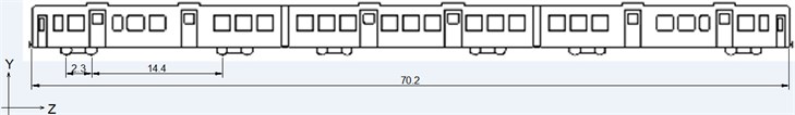
The vehicle running through the studied section is a S-592, from Alstom. Its maximum load per axle is 12 t, consists of three carriages, and the main distances between its elements are depicted in the following sketch (Fig. 3).
Fig. 3Registered rolling stock
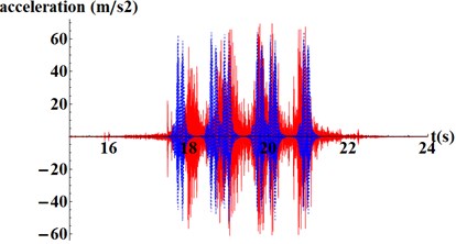
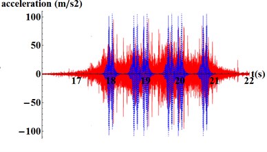
Being available the results from the model and the accelerations from the gathering campaign, a comparison between them is performed to reach the goals of the calibration stage. This comparison is presented in Fig. 4, where similar peak acceleration values can be appreciated for the real registers and the results from the model. Through this process, soil and ballast elasticity modulus and damping coefficient are set to: 200 MPa, 80 MPa and 0.0006 respectively.
From this verification it is concluded that a numerical model able to represent the vibrations in this track is available. Subsequently, the modal behavior of the track may be studied.
Fig. 4Comparison between real registers (red) and model results (blue): a) in the sleeper and b) in the rail web
a)
b)
3. Modal analysis
The natural frequencies of the bridge have been obtained from a modal analysis carried out by means of the FE model, being the geometry of the track and the structure the same as in the dynamic model. In the modal analysis, materials also have been assumed to present a linear-elastic behavior, damping has been neglected and the external actions have been disregarded. Consequently, the dynamic equation presented in Eq. (1) is reduced to Eq. (2):
In the linear system considered, free vibration is determined by harmonic functions as shown in Eq. (3):
In which represents the eigenvector associated to the mode shape of the th natural frequency ().
Combining Eq. (2) and Eq. (3), the modal analysis is performed solving Eq. (4):
Eq. (4) can be solved for values of the natural circular frequencies of the system and eigenvectors . Natural frequencies are then calculated as shown Eq. (5):
In single-track bridges, the main natural frequencies that may induce the resonance of the bridge are those related to the flexural shape modes since, due to the geometric and loading symmetry, torsional modes are not excited. Some authors as [2] claim that the first flexural mode is the most influential in the dynamic behavior of a bridge. In the present study, the firsts 20 natural frequencies (Table 3) are calculated by means of the FE model.
In Fig. 5, the mode shapes deformation is presented for the first and the third flexural modes of vibration.
Table 3Bridge modes of vibration. Flexural modes are highlighted
Number | Frequency (Hz) |
1 | 6.3794 |
2 | 7.3419 |
3 | 7.94 |
4 | 9.605 |
5 | 10.17 |
6 | 10.69 |
7 | 11.55 |
8 | 11.67 |
9 | 12.082 |
10 | 12.24 |
11 | 12.5664 |
12 | 12.6264 |
13 | 12.6264 |
14 | 12.99 |
15 | 14.475 |
16 | 14.9988 |
17 | 15.0867 |
18 | 15.33 |
19 | 16.695 |
20 | 17.4903 |
Fig. 5Shapes mode deformation at 10.17 Hz and 15.33Hz
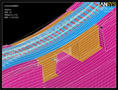
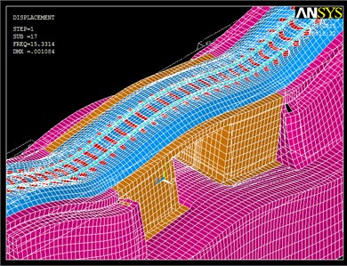
Once the modes of vibration of the system are known, in next section the natural frequencies associated to the flexural modes will be excited, and the displacements and accelerations induced by train passage under resonance conditions will be calculated. Furthermore, different scenarios will be analyzed so as to improve the track-structure behavior under these circumstances.
4. Analysis of different scenarios
In this section, first of all, the main flexural modes of vibration have been excited by the wheelsets passage. To do so, the distance between adjacent wheel axles has been set and different vehicle speeds have been simulated, thus inducing the natural frequencies of the system. Then, accelerations for each case have been calculated.
Moreover, the influence of different track parameters has been assessed: In the first scenario, improvements in ballast properties dues to a tamping process have been simulated; in the second scenario, changes in track damping have been assessed; and finally, in the third scenario the wooden sleepers available in the original track have been substituted by reinforced concrete sleepers, while steel railpads have been substituted by elastomeric railpads. These scenarios have also been studied both from the point of view of vertical displacements and accelerations.
It is well known that the repeated loads transmitted to the track by train passage may excite the natural frequencies of the bridge. Then, in the present study, a train of loads running over the track model have been simulated. Following the research carried out by [2], it may be said that the dynamic behavior of the bridge is determined mainly by its flexural modes. Thus, in the present research, the frequencies associated to these modes have been induced. Since frequencies are determined by Eq. (6):
Being, vehicle speed denoted by and the distance between adjacent loads by .
Then, to induce the frequencies associated to the main flexural modes, the distance between adjacent loads has been set according to the distance between adjacent axles, and different vehicle speeds have been fixed depending on the flexural mode that is being excited.
Following this procedure, Table 4 summarizes the studied cases.
Table 4Summary of the studied cases
Case | Mode | Frequency (Hz) | Vehicle speed (km/h) |
1 | 5 | 10.17 | 91.53 |
2 | 9 | 12.082 | 108.74 |
3 | 18 | 15.33 | 137.97 |
4 | 19 | 16.695 | 150.26 |
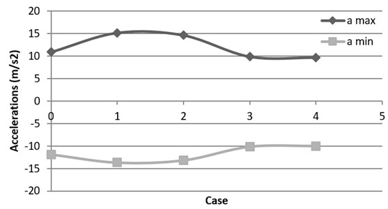
In Fig. 6 the accelerations calculated in the mid-span slab section for each case are shown. It may be highlighted that, according to the study performed by [2], the maximum accelerations are obtained for the first flexural mode.
Several authors, as [17] proved that the vertical accelerations are very sensitive to train speed being: the higher train speed, the higher the accelerations. Nevertheless, in this case, the higher the flexural mode, the higher the vehicle speed and then, according to Table 5, maximum acceleration values should be reached in Case 4. Regarding Fig. 6, the opposite behavior is shown in this case and it may be explained by the fact that the influence of resonance phenomenon is higher than the influence of vehicle speed.
Once the behavior of real track under resonance conditions is assessed, different scenarios are studied so as to evaluate the influence of different parameters on resonance phenomenon. In all the studied scenarios, it is supposed that the fifth mode of vibration is excited; since it has been proved that the most unfavorable situation from the point of view of vibrations is reached in this case.
Fig. 6Maximum and minimum accelerations for each flexural mode of vibration
4.1. Ballast improvement: Case A
In the present case, an improvement in ballast quality has been simulated. To this aim, the modulus of elasticity has been increased from the 80 MPa calibrated for the original model to 180 MPa, which is a common value for tracks recently tamped.
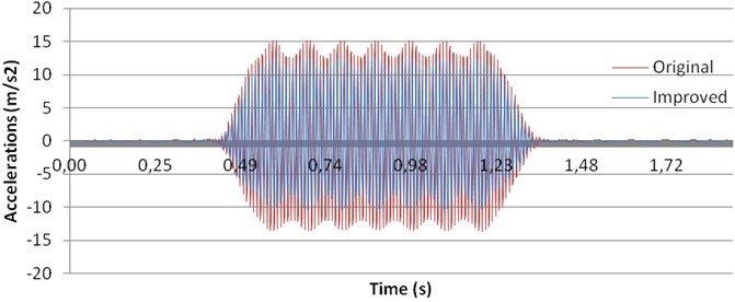
This analysis has been performed from the point of view of both vertical displacements and accelerations in the mid-span section of the bridge. In Fig. 7, the results for displacements are shown and, in Fig. 8, the results for accelerations.
Fig. 7Comparison between displacements before and after tamping process
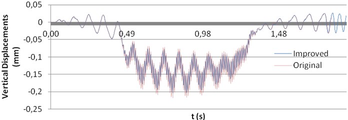
Fig. 8Comparison between accelerations before and after tamping process
According to Fig. 7, improvements in the ballast layer do not lead to significant changes in vertical displacements, although some diminution in the minimum values may be observed.
Nevertheless, the opposite behavior is presented for the accelerations, as seen in Fig. 8. In this case, increasing the stiffness of ballast layer induces high reductions in acceleration peaks. Then, this measure might be taken into account when resonance problems are found in short-span bridges so as to increase track security, passengers comfort and to reduce track damage and maintenance costs.
4.2. Influence of track damping: Case B
In this case, the influence of track damping has been assessed from the point of view of displacements and accelerations. To this aim, Rayleigh coefficient – set to 0.006 through the calibration process – has been changed: firstly, increased (0.009) and secondly decreased (0.003). The results of this analysis are presented in Fig. 9, for displacements, and in Fig. 10 for accelerations.
Fig. 9Influence of track damping on displacements
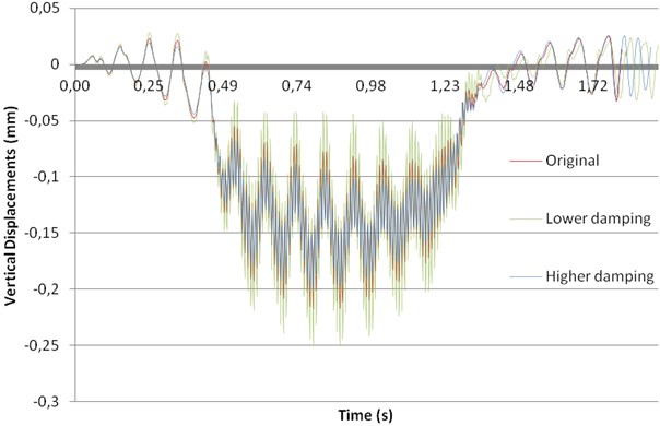
Fig. 10Influence of track damping on accelerations
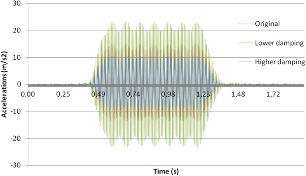
From this analysis, it may be clearly seen that the higher the damping, the lower both the displacements and the accelerations reached in the mid-span section of the bridge. Furthermore, comparing this case with the reductions obtained in Case A (ballast improvement), it may be concluded that the influence of track damping is much higher than the influence of ballast stiffness regarding both the vibrations and the accelerations. Thus, this measure should be taken into account by railway managers in problematic bridges under resonance conditions.
4.3. Changes in sleepers and railpads: Case C
The original track presented wooden sleepers and steel railpads. Although these elements may be commonly founded in old tracks, replacing them by reinforced concrete sleepers and elastomeric railpads would lead to improvements in track dynamic behavior. To quantify this improvement, said changes have been simulated.
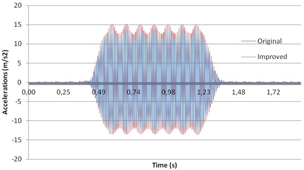
Results from this analysis have been presented in Fig. 11 for vertical displacements and in Fig. 12 for accelerations.
Fig. 11Influence of changes in sleepers and railpads on vertical displacements
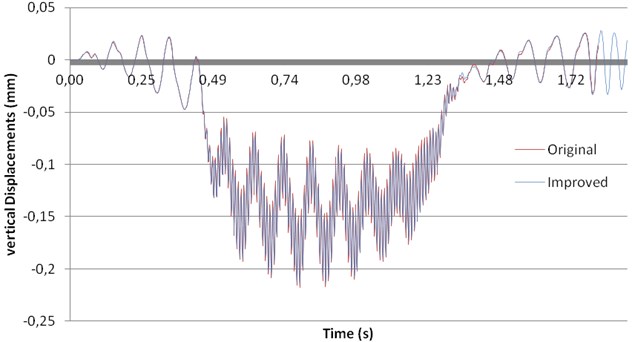
Fig. 12Influence of changes in sleepers and railpads on accelerations
On the one hand, from Fig. 11, where vertical displacements for both the original and the improved track are presented, it may be concluded that no noticeable changes are obtained from the point of view of vertical displacements.
On the other hand, according to Fig. 12, accelerations on the mid-span section of the bridge are reduced by changing sleepers and railpads. Nevertheless, although the reductions in vibrations are noticeable, this improvement is far from that reached by modifying track damping.
5. Conclusions
The current investigation aims to study the effect of resonance phenomena in a railway short-span bridge under different circumstances. To this aim, a FE model has been performed in time domain, and it has been calibrated and validated with experimental measurements.
To this goal, first of all, natural frequencies of the structures have been obtained by means of modal analysis. Then, frequencies associated to the main flexural modes have been induced by the train passage and, finally, different scenarios have been analyzed.
From this study, the following conclusions have been drawn:
• The higher the mode of vibrations, the lower the acceleration values obtained despite they are reached at higher vehicle speeds.
• The influence of vehicle speed is lower than the influence of resonance phenomenon
• The numerical model developed has provided accurate results for both shape modes and transient analysis. It allows designers to study the induced railway resonance phenomena in early design steps with a high accurate model.
• Improvements in ballast layer leads to slight decreases in vertical displacements and noticeable reductions in accelerations.
• Track damping is highly influent both from the point of view of track displacements and accelerations.
• Changes on sleepers and railpads only are influent on accelerations.
References
-
Domínguez J. Railways Bridges Dynamics for High-Speed Railways: Calculus Methods and Study of Resonance. 2001.
-
Museros P. Vehicle-Structure Interaction and Resonance Effects in Isostatic Railways Bridges for High-Sped Lines. 2002.
-
Lu Y., Mao L., Woodward P. Frequency characteristics of railway bridge response to moving trains with consideration of train mass. Engineering Structures, Vol. 42, 2012, p. 9-22.
-
Yang Y., Lin C. Vehicle bridge interaction dynamics and potential applications. Journal of Sound and Vibration, Vol. 284, Issues 1-2, 2005, p. 205-226.
-
Yang Y., Yau J. Vehicle bridge interaction element for dynamic analysis. Journal of Structural Engineering, Vol. 124, Issue 4, 1997, p. 1512-1518.
-
Lavado J., Doménech A. Dynamic performance of existing high-speed railway bridges under resonant conditions following a retrofit with fluid dampers supported on clamped auxiliary beams. Engineering Structures, Vol. 59, 2014, p. 255-374.
-
Timoshenko S. On the forced vibrations of bridges. Philosophical Magazine, Vol. 6, Issue 43, 1018, p. 1019-1922.
-
Tan C., Shore S. Response of horizontally curved bridge to moving load. Journal of Structural Engineering, Vol. 94, 1968, p. 2135-2151.
-
Olson M. On the fundamental moving load problem. Journal of Sound and Vibration, Vol. 145, Issue 2, 1991, p. 299-307.
-
Akin J., Mofid M. Numerical solution for response of beams with moving mass. Journal of Structural Engineering, Vol. 115, Issue 1, 1989, p. 120-131.
-
Lee H. Dynamic response of a beam with a moving mass. Journal of Sound and Vibration, Vol. 191, Issue 2, 1996, p. 289-294.
-
Foda M., Abdujabbar Z. A dynamic Green function formulation for the response of a beam structure to a moving mass. Journal of Sound and Vibration, Vol. 210, Issue 3, 1998, p. 295-306.
-
Yang Y., Wu Y. A versatile element for analyzing vehicle bridge interaction response. Engineering Structures, Vol. 23, Issue 1, 2001, p. 452-469.
-
Pesterev A., Yang B., Bergman L., Tan C. Response of elastic continuum carrying multiple moving oscillators. Journal of Engineering Mechanics, Vol. 127, Issue 3, 2001, p. 260-265.
-
Real J., Zamorano C., Hernández C., Comendador R., Real T. Computational considerations of 3-D finite element method models of railway vibration prediction in ballasted tracks. Journal of Vibroengineering, Vol. 16, Issue 4, 2014, p. 1709-1722.
-
El Kacimi A., Woodward P., Laghrouche O., Medero G. Time domain 3D finite modeling of train-induced vibration at high speed. Computers and Structures, Vol. 118, Issue 8, 2013, p. 66-73.
-
Gia N. Dynamic Effects Due to Railways Traffic Over Track Infrastructure and Structures. 2013.
Cited by
About this article

