Abstract
Environmental micro-vibration affects the accuracy of precision measurement devices. Passive isolation system can isolate most external vibration, decreasing its stiffness will improve isolation effect. Permanent magnet negative-stiffness device (PMNSD), which is mainly constructed from three permanent magnets, can decrease the system dynamic stiffness of isolation system without any effect to the static stiffness, when it is used parallel with positive-stiffness isolator. The mechanism of its negative stiffness is analyzed, and its stiffness is calculated by theory method and finite element method, it proves that the stiffness will decrease with the decrease of the initial air gap of magnets. A micro-vibration isolation platform using PMNSDs and air springs is constructed, it can carry many kinds of measurement instruments which weight 0-2000 Kg, keeping the system natural frequency under 1 Hz, it has good isolation capacity for micro-vibration over 2 Hz. The PMNSD will have greatly practical applications for its tunable negative stiffness, zero static stiffness, contact free, long life and so on.
1. Introduction
Along with the development of science and technology, manufacture, measurement and use of precision instrument make strict request of environment vibration [1, 2], such as that the calibration of high precision inertial instrument need the environment vibration acceleration controlled under 10-6 g. High precision vibration isolation measurement platform is a extremely effective method to solve the environment vibration problem, it can isolate the ground vibration caused by cars or metros, staff walk, other machines like air-condition, and so on, efficiently. Active vibration control has been used in many such platforms [3], and achieves great result, but the systems are so complicate and expensive to limit their widely used. High performance passive isolation platforms [4, 5] are still main solution. A lot of research is performed to improve the isolation effect, the quasi-zero-stiffness isolator [6, 7] is put forward as a efficient solution for the micro-vibration isolation recently. Combining with positive and negative stiffness parallel, this new type isolator achieves high static stiffness which makes the system has high load capacity, and low dynamic stiffness which makes the system has low natural frequency and thus great vibration isolation performance. This thesis introduce a new kind of negative stiffness device constructed by three permanent magnets, the mechanism of negative stiffness is analyzed, the stiffness is calculated through theory method and finite element method. Then using air spring combined with the permanent magnet negative stiffness device (PMNSD) parallel, a micro-vibration isolation platform is established, it has large load range and low nature frequency, satisfying many kinds of precision measurement instruments.
2. Mechanism of negative stiffness
Two magnets attract each other when opposite poles face to face. Many researchers have studied the exact expression of the relation between magnetic force and the air gap , but it is so difficult for complicated structure. To simplify the problem, the relation can be expressed by a third order polynomial:
where , , , are the magnetic constants that depend on the material and structure of magnets. It shows that the magnetic force is nonlinear to the air gap , the constants come from fitting the experiment data or finite element analysis.
If three same magnets arrange in the same pole direction, shown in Fig. 1, the middle magnet has the same air gap, , to the two side magnets and , so magnet is attracted by two side magnets , , at the same time. When magnets and are fixed, magnet moves a small displacement, , the two magnetic forces are given by:
Fig. 1Mechanism of negative stiffness
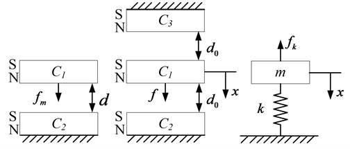
So the joint force on magnet , is given by:
If the middle magnet moves toward magnets , the air gap between magnet and magnet is smaller than that between magnet and magnet , the force magnet attracting magnet , , is larger than that magnet attracting magnet , , the joint force is toward magnet , and increases with increase of . The opposite is the same. Comparing to the mass-spring system, the magnetic force is opposite to the spring recover force , thus the three magnets mechanism has negative stiffness.
For micro-vibration, the motion displacement, , is extremely tiny, the stiffness of middle magnet approximately equals:
Eq. (4) shows that the stiffness decreases with the decrease of initial air gap . It can be called tuned negative stiffness character.
3. Structure of PMNSD
On the basis of mechanism analysis above, one type of PMNSD is depicted in Fig. 2. The PMNSD contain three 100 mm (length) × 70 mm (width) × 20 mm (thickness) NdFeB permanent magnets, upper magnet and under magnet are glued in the magnet carriages, two magnet carriages are installed in the base carriage through two bi-direction screws which are glued with adjustment hand wheels. The middle magnet is glued in the movable carriage, and placed in the center between upper and under magnets. The base carriage is fixed on the under platform, and the movable carriage is fixed on upper platform.
Fig. 2Structure of PMNSD
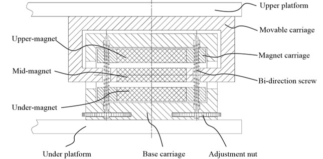
The base carriage is made of steel material with high permeability, it construct a close loop around the three magnets, the use of steel base carriage brings two advantages, firstly most of the magnetic line will place inside the base carriage, there is too weak magnetic field outside the PMNSD to magnetize other devices around, secondly there is almost not any magnetic flux leakage along the magnetic circuit, the magnetic force between magnets is maximized, thus the PMNSD can produce the strongest negative stiffness.
When the distance between upper and under platform is equal to the design height of PMNSD, the middle magnet is at the exact center between upper and under magnet, there is , from Eq. (3) the magnetic force on middle magnet , thus PMNSD brings no extra force between two platforms, it can be called zero extra load character.
When rotating the two adjustment hand wheels synchronously, the distance between upper magnet and under magnet can be adjust, the initial air gap can be adjusted from 2 mm to 10 mm, keeping the air gap between upper magnet and middle magnet the same as the air gap between middle magnet and under magnet all the time, thus the stiffness of PMNSD can be adjusted by rotating the adjustment hand wheel.
The PMNSD has an another function as limit-displacement device, for the middle magnet can move only between upper and under magnets, so the upper platform is limit in ±, avoiding the isolation system move too large displacement.
Base on the mechanism of negative stiffness, many other types of PMNSD can be designed.
4. Finite element analysis of PMNSD
Finite element method is a good choice to analysis PMNSD without any object experiments which cost lots of money and time. ANSYS has good capacity to analysis magnetic problem.
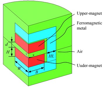
Fig. 3 depicts the two magnets model; it is a quartering model for the whole model has two symmetrical plane. The real size of upper magnet and under magnet is ××, the air gap between magnets is , around the magnets there is ferromagnetic metal whose thickness is , outside the ferromagnetic metal is air. APDL is used for fast analysis, a loop of is established.
Table 1Parameters in two magnets model
(mm) | (mm) | (mm) | (mm) | (mm) | (T) | (KA/m) |
50 | 35 | 20 | 2-120 | 20 | 1.5 | 995 |
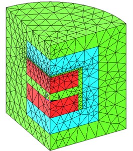
To establish the electromagnetic analysis, tetrahedral coupled-field solid element SOLID98 is used for all models. There are three kinds of material types, magnets, ferromagnetic and air, material define is detailed in Table 2 Free mesh is used, the smart size is 1, mesh shape choose ‘Tet’, the number of elements is also listed in Table 2. To calculate the magnetic force between two magnets, force and torque boundary conditions are applied to the upper-magnet element component.
Table 2Material define and number of element
Type | Material define | Number of element | ||||
20 | 50 | 100 | ||||
Magnet | MURX = 1.5 | Upper | 824 | 799 | 725 | 467 |
MGZZ = 995E5 | Under | 238 | 222 | 231 | 223 | |
Ferromagnetic metal | MURX = 1E5 (or MURX = 1) | 1960 | 1938 | 1875 | 1885 | |
Air | MURX = 1 | 4753 | 5327 | 5636 | 5532 | |
Fig. 3Finite element model of two magnets
In order to get the magnetic constants of PMNSD, the magnetic force is calculated when the air gap increase from 2 mm to 120 mm, the relationship between magnetic force and air gap is result in Fig. 4, it shows that magnetic force is greatly nonlinear relate to air gap.
By fitting the data (2-40 mm) in third order polynomial, the magnetic constants are given by:
Fig. 4Relationship between magnetic force and air gap of two magnets
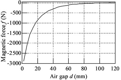
Fig. 5Comparison between experiment data and fit data
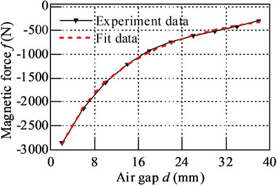
The experiment data from finite element analyze and fit data are plotted in Fig. 5, it shows that great match between them, and the error round in –1.61 %-1.13 %.
To compare the character whether there is ferromagnetic metal around magnets or not, set the relative permeability of ferromagnetic metal material or 1×10⁵, the magnetic flux density result is depicted in Fig. 6, and the magnetic force is 763.9 N and 1038.7 N.
Fig. 6Magnetic flux density result: a) without ferromagnetic metal, b) with ferromagnetic metal
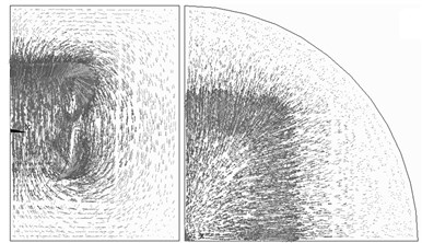
a)
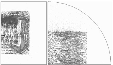
b)
It shows that there is strong magnetic flux all around the model when there is not ferromagnetic metal, and most of magnetic flux is in the ferromagnetic metal when there is ferromagnetic metal, there is just very little magnetic leakage. The magnetic force between two magnets is much bigger with ferromagnetic metal than that without ferromagnetic metal.
Fig. 7 depicts the finite element model of PMNSD with three magnets, for different initial air gap , the magnetic force on middle magnet is calculated when middle magnet moves in ±1 mm. To finish this analysis, two loops are established. Inner loop changes the displacement of middle magnet from –1 mm to 1 mm in 21 steps, outer loop changes the initial air gap from 2 mm to 10 mm in 5 steps. Force and torque boundary conditions are applied to the middle-magnet element component. When , the numbers of element for all are listed in Table 3.
Fig. 7Finite element model of PMNSD
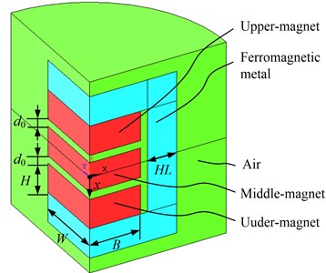
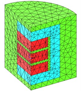
Table 3Number of PMNSD model element
Type | Number of element | |||||
2 | 4 | 6 | 8 | 10 | ||
Magnet | Upper | 2241 | 604 | 335 | 217 | 201 |
Middle | 6500 | 1027 | 333 | 229 | 304 | |
Under | 2417 | 612 | 514 | 240 | 219 | |
Ferromagnetic metal | 1615 | 1769 | 1598 | 1437 | 1480 | |
Air | 7805 | 4892 | 4198 | 3847 | 3828 | |
The calculation result shows in Fig. 8, it shows that the magnetic force decrease with the increase of displacement , so the stiffness is negative. For the displacement is so small, the - curves are almost straight lines, so the stiffness can be fitted as the slope of - curves.
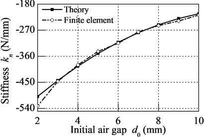
To examine the relationship between stiffness and initial air gap , take the parameters in Eq. (5) into Eq. (4), result shows by solid line in Fig. 9. The stiffness of PMNSD with different initial air gap is depicted by dash line. It shows great match between theory method and finite element method. When tuning the initial air gap from 2 mm to 10 mm, the stiffness increases from –532 N/mm to –218 N/mm.
Fig. 8Magnetic force on middle magnet of PMNSD for different air gap
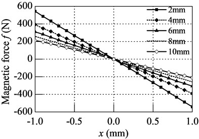
Fig. 9Stiffness – initial air gap characteristic
5. System component and property of micro-vibration isolation platform
The micro-vibration isolation platform uses four air springs to support the weight of upper platform and devices. Each air spring is controlled by a intake valve and a outlet valve, there are four displacement sensors beside four air springs to measure the working height of air springs, one controller get the height information, and calculates the exact attitude of platform, decides which air spring should be inflated or deflated compressed air. So no matter how weight the device is, all the air springs can be kept at design height.
If PMNSD is installed parallel beside air spring, it will not bring any effect to load capacity of air spring for its zero extra load character, and its negative stiffness can offset part of positive stiffness of air spring.
Because air spring works at design height all the time, its effective area remains unchanged, and the effective area change rate can be ignored for micro vibration, thus the stiffness of spring is approximately given by:
where is polytropic exponent, is the volume of air spring, is load of air spring. It shows that stiffness increases with the increase of load. The natural frequency of air spring is given by:
It shows that the natural frequency of air spring keeps constant, no matter how much weight is its load.
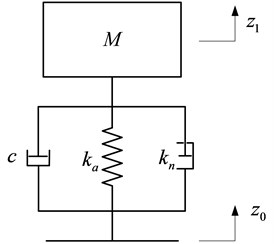
Assuming that the micro-vibration isolation platform moves only along the vertical direction, it can be taken as single-DOF system, depicted in Fig. 10, is the total load of upper platform and device, is the damping of air spring.
The system stiffness, , is given by:
And the natural frequency of system is given by:
So the transmissibility of the isolation platform is given by:
where is damping ratio, is disturbing frequency.
Fig. 10Diagram of isolation system
In order to keep the same isolation capacity when load different devices with different weight, should keep constant, thus should be tuned to match the change of , substituting Eq. (4), Eq. (6), Eq. (8) into Eq. (9), the suitable air gap of magnets is given by:
For different instruments on the platform, the load of air spring is different, the stiffness increases while the load increases, the stiffness of PMNSD should be tuned to keep the natural frequency as 1 Hz by turning the hand wheel.
Some real constants of micro-vibration platform are list in Table 4.
Table 4Constants of micro-vibration platform
Polytropic exponent | 1.4 |
Effective area of air spring (m2) | 1.33×10⁻² |
Volume of air spring (m3) | 3.9×10⁻³ |
Mass of upper platform (Kg) | 2000 |
Mass of instrument (Kg) | 0-2000 |
The suitable air gap of PMNSD is calculated using Eq. (11), result lists in Table 5. It shows that when tuned the air gap from 9.6 mm to 3.1 mm, the PMNSD can bring enough negative stiffness to keep the system natural frequency being 1 Hz. On the other hand, the PMNSD can provide enough negative stiffness to keep the system natural frequency under 1 Hz, Table 6 gives the suitable air gap for different natural frequency.
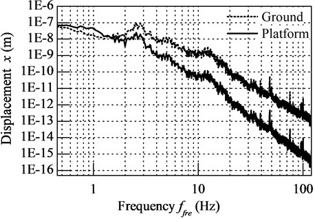
The dash line in Fig. 11 plots the vibration of laboratory ground where micro-vibration isolation platform places. When the natural frequency of platform is tuned at 1 Hz, the ground vibration is greatly isolated above 2Hz, the vibration of platform is plotted as solid line in Fig. 11.
Table 5Result of suitable air gap of PMNSD for different instruments
Mass of instrument (Kg) | 0 | 400 | 800 | 1200 | 1600 | 2000 |
Stiffness of air spring (N/mm) | 239.3 | 287.2 | 335.0 | 382.9 | 430.8 | 478.6 |
System stiffness needs (N/mm) | 19.7 | 23.7 | 27.6 | 31.6 | 35.5 | 39.5 |
Stiffness of PMNSD (N/mm) | –219.6 | –263.5 | –307.4 | –351.3 | –395.2 | –439.2 |
Suitable air gap of PMNSD (mm) | 9.6 | 7.5 | 6.1 | 5.0 | 4.0 | 3.1 |
Table 6Suitable air gap for different natural frequency
Natural frequency | Instrument weight | |||||
0 | 400 | 800 | 1200 | 1600 | 2000 | |
0.75 Hz | 9.1 | 7.2 | 5.8 | 4.6 | 3.7 | 2.8 |
0.5 Hz | 8.8 | 6.9 | 5.6 | 4.4 | 3.4 | 2.5 |
0.25 Hz | 8.6 | 6.8 | 5.4 | 4.3 | 3.3 | 2.4 |
0.1 Hz | 8.5 | 6.7 | 5.4 | 4.3 | 3.3 | 2.4 |
Fig. 11Isolation effect of Micro-vibration isolation platform
6. Conclusion
The mechanism of PMNSD’s negative stiffness is analyzed. The stiffness is calculated by theory method and finite element method, and the results match each other well. A particular type of PMNSD is designed, its negative stiffness can be adjusted by adjusting the hand wheel. It brings no extra load, not affecting the static stiffness of system. It also can be used as limit-displacement device. The micro-vibration isolation platform using four PMNSDs and four air springs parallel can keep the system natural frequency under 1 Hz for different weight of measurement instrument. It has good isolation capacity for micro-vibration over 2 Hz. The PMNSD can be widely used in different isolation systems.
References
-
Rivin E. I. Vibration isolation of precision equipment. Precision Engineering, Vol. 17, Issue 1, 1995, p. 41-56.
-
Gordon C. G. Generic criteria for vibration-sensitive equipment. Proceedings SPIE 1619, Vibration Control in Microelectronics, Optics, and Metrology, San Jose, CA, 1991.
-
Nakamura Y., Nakayama M., Masuda K. Development of active six-degree-of-freedom micro-vibration control system using hybrid actuators comprising air actuators and giant magnetostrictive actuators. Smart Mater Structures, Vol. 15, Issue 4, 2006, p. 1113-1160.
-
Zhang W., Yin J. L., Jin L. B., Li D. S. Study of natural frequency of precise air-spring isolation platform. Transducer and Microsystem Technologies, Vol. 30, Issue 10, 2011, p. 12-14.
-
Lee J., Dong Y., Lee M. G. Passive vibration reduction with silicone spring and dynamic absorber. Physics Procedia, Vol. 19, 2011, p. 431-435.
-
Carrella A., Brennan M. J., Waters T. P. On the design of a high-static-low-dynamic stiffness isolator using linear mechanical springs and magnets. Journal of Sound and Vibration, Vol. 315, 2008, p. 712-720.
-
Carrella A., Brennan M. J., Waters T. P. Force and displacement transmissibility of a nonlinear isolator with high-static-low-dynamic-stiffness. International Journal of Mechanical Sciences, Vol. 55, Issue 1, 2012, p. 22-29.
About this article

