Abstract
Optical beam deflectors are used to control direction of the optical beam therefore accuracy of the optical system strongly depends on dynamic characteristic of the deflector. Three degrees of freedom (3DOF) piezoelectric micro-actuator for optical beam deflector is investigated in the paper. Piezoelectric micro-actuator consists of piezoelectric cylinder and ferromagnetic hemisphere that contacts the cylinder in the three points. Electrodes of the outer surface of the cylinder are divided into three sections. Three harmonic electric signals are used for piezoelectric cylinder excitation. Numerical and experimental study was performed to analyse dynamic characteristics of the piezoelectric actuator. Results of the studies are compared and discussed.
1. Introduction
Optical beam deflectors are widely used for many applications such as microscopy, optical communication, laser radar systems, target-tracking systems, land survey systems, laser printers, space technologies, medicine, laser machining, metrology, laser scanning and other [1-5]. Optical beam direction control is also important for the laser beam communication system to control swarm of the pico satellites in space [1]. Beam positioning and control systems must have the following features as flexibility, high positioning accuracy, high resolution, quick response. Most of the existing optical beam positioning systems have large dimensions and consume considerable amount of electrical energy, therefore development of small size deflecting system is relevant [2]. Small size micro-optical components have the following advantages as compact size, fast response, and low-energy consumption, therefore positioning devices owning advanced features can be developed.
During the recent years, a lot of new micro optical devices and systems were developed i.e. micro beam splitters [6], micro lenses [7-9], micro positioners [10-13] and micro mirrors-deflectors [2-5, 14-16]. There are also reports on the piezoelectric type deflectors. This type of deflectors has simple mechanical structure, high holding force and mechanical durability [17]. Most of the authors use piezoelectric bending bimorphs as driving actuators of the deflectors. High resolution can be achieved using bending bimorphs but rotation angle of the deflector is limited [18, 19]. Also these positioning devices have just one degree of freedom.
3DOF piezoelectric micro-actuator for the optical beam deflector in proposed and analysed in the paper. Proposed design of the piezoelectric deflector allows achieving unlimited rotation angle of the mirror about three axes. High resolution of the deflector rotation can be achieved as well. Numerical modelling and experimental study was performed to analyse dynamic characteristics of the piezoelectric deflector.
2. Principle design of piezoelectric deflector
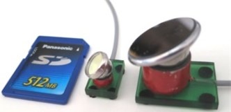
Investigated optical beam deflector consists of piezoelectric cylinder, passive ferromagnetic hemisphere, mirror and permanent magnet (Fig. 1(a), 1(b)). Piezoelectric cylinder has three contact points located on the top surface of the cylinder. Contact points are used to rotate hemisphere. The magnet is used to generate magnetic force and to preload hemisphere to the cylinder. Outer electrodes of the piezoelectric cylinder are divided into three equal sections as shown in Fig. 1(c). Inner electrode of the cylinder is grounded. Contact points generates the elliptical movement when harmonic voltage is applied on the outer electrodes therefore hemisphere is rotated by particular angle. Rotational movement about three axes are obtained when different electrode sections are excited. Rotating direction of the hemisphere around the , and axis is achieved applying different algorithms of electrodes excitation. The theory of elliptical trajectories formation and generation of rotational movement of the hemisphere was analysed in [20].
Fig. 1Piezoelectric deflector: 1 – laser beam, 2 – mirror, 3 – passive ferromagnetic sphere, 4 – piezoelectric cylinder, 5 – permanent magnet, 6 – contact points between passive ferromagnetic hemisphere and piezoelectric cylinder, 7 – electrodes
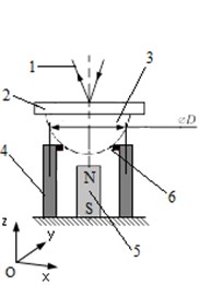
a) Schematic view
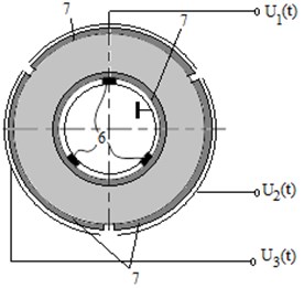
b) Configuration of electrodes
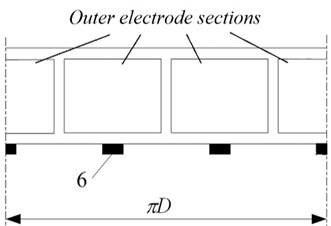
c) Outer electrode pattern
3. Numerical modelling and analysis
Finite element modelling (FEM) was used to perform harmonic response analysis and to calculate trajectories of the contact points motion when different electrodes are excited. FEM software ANSYS was employed for the simulation. Dimensions of piezoelectric cylinder were set to (××) 14×11×10 mm. PZT4 piezoelectric material was used for the simulation. Fig. 2(a) demonstrates the FEM model of a piezoelectric actuator. Cylinder has radial polarization. The actuator was actuated by 20 V harmonic electric signal. Shape of the standing wave of the cylinder at 112.7 kHz is presented in Fig. 2(b). This resonant frequency was set as operating frequency of the actuator.
Fig. 2Numerical modelling of the cylindrical actuator
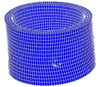
a) FEM model
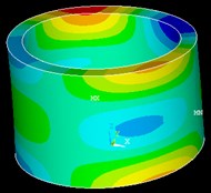
b) Deformations of the actuator (112.7 kHz)
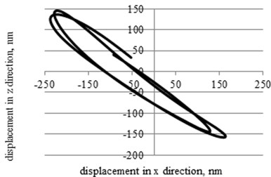
Results of harmonic response analysis was used to calculate trajectories of contact points motion when sinusoidal voltage was applied on different outer electrodes. Resonant frequency of 112.7 kHz was defined. The results of the calculations are presented in Fig. 3 where trajectories of all three contact points motion in plane are given.
Fig. 3The trajectories of the contact points movement in the xz plane (excitations of piezoelectric cylinder at 112.7 kHz)
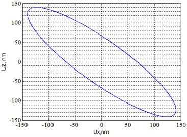
a) First contact point
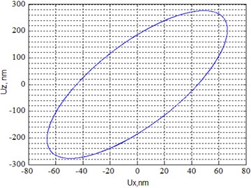
b) Second contact point
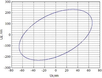
c) Third contact point
While analysing the trajectories of the contact point motion, it can be noticed that they have ellipsoidal shapes. The lengths of the major axes of the ellipses are 0.39 µm, 0.53 µm and 0.41 µm, and leaning angle of the major axis of the ellipses are 45.2°, 14.4° and 19.1° respectively for the first, second and third contact point (Fig. 3). It must be mentioned that length of the ellipses major axes is different because of the different location of the points in plane of coordinate plane.
4. Experimental measurement and results
A prototype piezoelectric deflector was made for experimental study (Fig. 4). Experimental investigation aimed to find out resonant frequency of piezoelectric cylinder, trajectories of the contact points and resolution of the rotation angle of the deflector. Shape of the piezoelectric actuator at the resonance frequency was obtained with the help of holographic imaging method. Holography system PRISM (Precise Real-time Instrument for Surface Measurement) was used for measurements. The experimental setup composed of control block, object beam splitter and camera (Fig. 5). Piezoelectric drive is not shown in this setup. The actuator was actuated by 20 V electric signal at the frequency 110.2 kHz. The holographic images of the oscillations amplitudes are presented in Fig. 6.
Fig. 4Prototype piezoelectric deflector
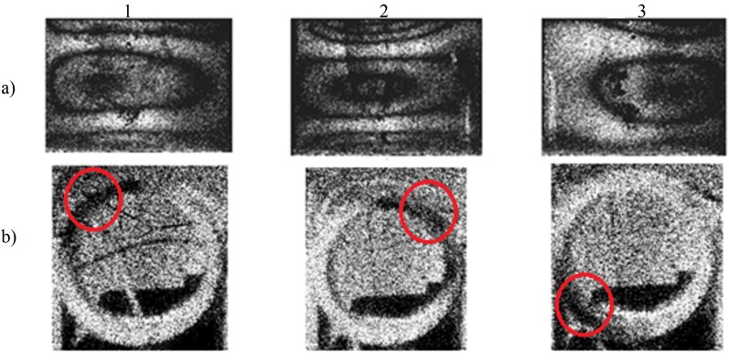
The visible dark areas illustrate the maximum of vibrations amplitudes and the light zones represent the minimum of oscillation amplitudes. Fig. 6(a) illustrates deformations of the piezoelectric cylinder area, where outer electrodes are located. Fig. 6(b) shows top view of the cylinder. The contacting elements are installed in the areas of the maximum oscillations (Fig. 6(b)).
Fig. 5Experimental setup of piezoelectric cylinder surface deformation measurement using holographic interferometry system PRISM: 1 – control block, 2 – object beam splitter, 3 – camera
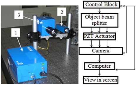
Fig. 6Holographic view (20 V, 110.2 kHz): a) deformations of piezoelectric cylinder, b) installation places of contact elements
Trajectories of contact points motion and the resolution of piezoelectric deflector were measured using another experimental set up consisted of a programmable signal generator, laser Doppler Vibrometer Polytec TM, high voltage amplifier, analog-digital converter PicoScope, and a computer with installed scanning vibrometer software package (PSV 8.8, Polytec Inc., Irvine, CA) (Fig. 7).
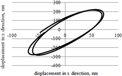
The experimental results revealed that maximum rotation speed of the mirror is achieved at 110.2 kHz. It also was validated experimentally that the contacting points move in ellipse shape trajectory (Fig. 8). However, trajectories of the different points are not equal. Also parameters of the ellipses do not fully correspond with results of numerical modelling. Differences mainly comes because of the manufacturing and assembling errors of the prototype actuator, differences in areas of the electrodes, properties of the materials, vibration distribution asymmetries of the piezoelectric actuator.
Fig. 7Experimental set up. Here: 1 – piezoelectric deflector, 2 – laser Doppler Vibrometer Polytec TM, 3 – high voltage amplifier, 4 – signal generator Agilent 33220A, 5 – PicoScope-3424, 6 – computer
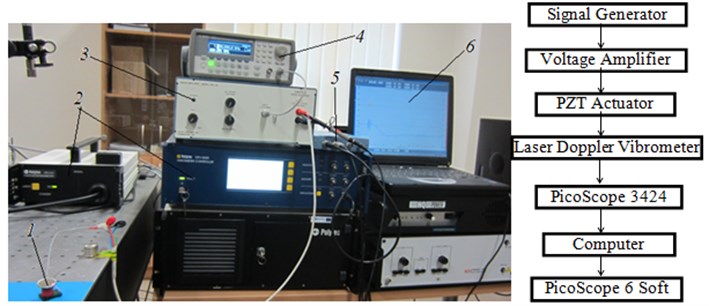
Fig. 8The trajectories of contact points movement in the xz plane (110,2 kHz, 20 V)
a) First contact point
b) Second contact point
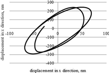
c) Third contact point
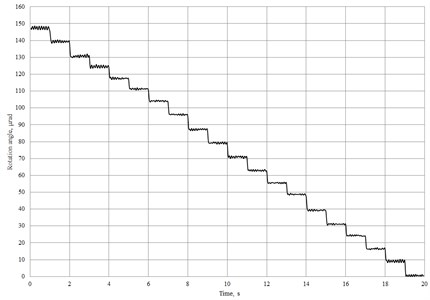
Resolution of the deflector rotation angle was determined by actuating piezoelectric actuator with a burst type electric signal. Burst period was 1 s, 2 cycles at 110.2 kHz frequency were applied. Resolution of the rotational angle is defined as a rotational angle of the deflector obtained from one burst type signal. Results of the experimental measurements were obtained using software package PSV 8.8 (Polytec Inc.) and subsequently graph was plotted (Fig. 9). Measured average resolution of the rotation angle of the piezoelectric deflector is 8 μrad.
Fig. 9Measured rotation angle of piezoelectric deflector
5. Conclusions
3DOF piezoelectric micro-deflector was developed. Numerical analysis of the actuator has shown possibilities to achieve elliptic trajectory of contact points movement when piezoelectric actuator is excited by harmonic electric signal. Experimental investigation of the actuator confirmed the main results of numerical analysis and the possibility to achieve rotating movement of the deflector about three axes. Average resolution of the rotation angle is 8 μrad.
References
-
Chao Y., Ying Z. Apparatus for Dynamic Control of Light Direction in a Broad Field of View. U.S. Patent No. 6,204,955, 2001.
-
Qiu Z. Optical MEMS. Microelectromechanical Systems and Devices, Editor Nazmul Islam, InTech, 2012, p. 291-330.
-
Glo S., Go R., Possner T. Micro-opto-mechanical beam deflectors. Optical Engineering, Vol. 36, Issue 5, 1997, p. 1339-1345.
-
Qiu Z., Pulskamp J. S., Lin X., Rhee C. H., Wang T., Polcawich R. G., Oldham K. Large displacement vertical translational actuator based on piezoelectric thin films. Journal of Micromechanics and Microengineering, Vol. 20, Issue 7, 2010, p. 1-10.
-
Wu L., Dooley S., Watson E., McManamon P. F., Xie H. A tip-tilt-piston micromirror array for optical phased array applications. Journal of Microelectromechanical Systems, Vol. 19, Issue 6, 2012, p. 1450-1461.
-
Wu M. C. Micromachining for optical and optometric systems. Proceedings of the IEEE, Vol. 85, Issue 11, 1997, p. 1833-1856.
-
Kumnorkaew P., Ee Y. K., Tansu N., Gilchrist J. F. Investigation of the deposition of microsphere monolayers for fabrication of microlens arrays. Langmuir, Vol. 24, 2008, p. 12150-12157.
-
Borrelli N. F. Microoptics Technology: Fabrication and Applications of Lens Arrays and Devices. Second Edition, Marcel Dekker Inc., New York, 1999.
-
Grilli S., Miccio L., Vespini V., Finizio A., De Nicola S., Ferraro P. Liquid micro-lens array activated by selective electrowetting on lithium niobate substrates. Optics Express, Vol. 16, Issue 11, 2008, p. 8084-8093.
-
Kim C. H., Kim Y. K. Micro XY-stage using silicon on a glass substrate. Journal of Micromechanics and Microengineering, Vol. 12, Issue 2, 2002, p. 103-107.
-
Gu L., Li X., Bao H., Liu B., Wang Y., Liu M., Cheng B. Single-wafer-processed nano-positioning XY-stages with trench-sidewall micromachining technology. Journal of Micromechanics and Microengineering, Vol. 16, Issue 7, 2006, p. 1349-1357.
-
Gorman J. J., Kim Y. S. Dagalakis N. G. Control of MEMS nanopositioners with nano-scale resolution. ASME International Mechanical Engineering Congress and Exposition, 2006, p. 151-159.
-
Chu L. L., Gianchandani Y. B. A micromachined 2D positioner with electrothermal actuation and sub-nanometer capacitive sensing. Journal of Micromechanics and Microengineering, Vol. 13, Issue 2, 2003, p. 279-285.
-
Douglass M. R. Lifetime estimates and unique failure mechanisms of the Digital Micromirror Device (DMD). The 36th Annual IEEE International Reliability Physics Symposium Proceedings, 1998, p. 9-12.
-
Fan L., Gloeckner S., Dobblelaere P. D., Patra S., Reiley D., King C., Husain A. Digital MEMS switch for planar photonic crossconnects. Optical Fiber Communication Conference and Exhibit, 2002, p. 93-94.
-
Hishinuma Y., Yang E. H. Piezoelectric unimorph microactuator arrays for single-crystal silicon continuous-membrane deformable mirror. Journal of Microelectromechanical Systems, Vol. 15, Issue 2, 2006, p. 370-379.
-
Tabib-Azar M. Microactuators Electrical, Magnetic, Thermal, Optical, Mechanical, Chemical and Smart Structures. Kluwer Academic Publishers, 1998, p 139-141.
-
Fung F. R., Chao S. C. Dynamic analysis of an optical beam deflector. Sensors and Actuators, Vol. 84, Issue 2000, 2010, p. 1-6.
-
Kim S. J., Cho Y. H., Nam H. J., Bu J. U. Piezoelectrically pushed rotational micromirrors using detached PZT actuators for wide-angle optical switch applications. Journal of Micromechanics and Microengineering, 18, p. 12-2008.
-
Hu M., Du H., Ling S. F., Teo J. K. A piezoelectric spherical motor with two degree-of-freedom. Sensors and Actuators A: Physical, Vol. 94, Issue 1, 2001, p. 113-116.
Cited by
About this article

The work was supported by the Research Council of Lithuania under the projects PiezoDeflect No. MIP-045/2014 and OptoControl No. TEC-02/2015.
RB conceived the concept of active kinematic pairs and participated in design of the investigated deflector. SN and VJ carried out the experimental investigations: optical measurements and visualization of vibrations of the investigated device and drafted the manuscript. VM made literature review and helped to draft the manuscript. GK and DM conducted the theoretical investigation of dynamics of the deflector. All authors read and approved the final manuscript.
