Abstract
Dynamic response of concrete lining structure in high pressure diversion tunnel under seismic load is of great importance for engineering design and safety assessment. In light of the basic idea of static damage constitutive in strain space, a dynamic damage and cracking model of concrete suitable for programming is established. Based on the explicit finite element method for analyzing the dynamic response of single-phase solid and fluid medium, combining with the boundary conditions at coupling interface, a dynamic explicit finite element solving format considering the coupling interaction of lining and inner water is presented. This method can directly integrate, solve without simultaneous equations, and greatly simplify the calculation process. Moreover, it can be easily used to analyze wave propagation problems with a variety of mediums. According to the damage evolution properties of concrete lining under seismic load, a calculation method of permeability coefficient considering the effect of damage and cracking is put forward, and the inner water exosmosis process with lining cracks is analyzed. The calculation results of engineering example can reasonably reflect the seismic response characteristics of concrete lining structure in high pressure diversion tunnel, and an effective analysis method is provided for the aseismic design of hydraulic tunnel.
1. Introduction
The spatial distribution of water resources is extremely uneven worldwide, which highlights the contradiction between water supply and demand. The development and utilization of water resources is gradually turning to the upstream of each watershed. So the long distance basin water diversion and power generation become the important developing directions of water conservancy and hydropower projects in the long run. The long distance diversion tunnels usually cross high earthquake intensity region, facing serious seismic stability problem [1-4]. Moreover, with the vigorous development of economic construction, more and more diversion tunnels with high head and large diameter appear, and the liquid sloshing with high pressure and great mass brings huge challenge to the seismic stability. Therefore, researching the anti-seismic stability of long distance water diversion project is of great significance for guaranteeing the safe and steady operation of the project.
The key to seismic stability analysis of high pressure diversion tunnel lies in the seismic response of concrete lining structure, so it is particularly important to establish a scientific and practical dynamic constitutive model for concrete. The current dynamic constitutive models are primarily nonlinear elasticity [5], plasticity [6], viscoplasticity [7, 8] and damage model [9, 10], which are usually established on the basis of experimental studies, and cannot be widely applied on account of many uncertain parameters, ignoring the fatigue damage characteristics under dynamic cyclic loading, iterative calculation which adversely affects the speed and precision. Furthermore, it lacks an effective simulation for dynamic damage and cracking process of lining structure. When analyzing the dynamic response of concrete lining structure under earthquake excitation, the interaction of inner water and lining should be taken into consideration, which is also proposed in aseismic design codes at home and abroad. However, current researches aimed at the dynamic interaction between lining structure and water in high pressure diversion tunnel under seismic load are very few, and the calculation and evaluation of hydrodynamic pressure are not clear. The interaction between inner water and lining structure belongs to the typical fluid-structure interface coupling problem [11, 12]. Studies on fluid-structure coupling problem have quickly developed in hydraulic, marine and other fields since 1980s, such as the liquid sloshing in the liquid reservoir vessel [13, 14], dam reservoir water fluctuation [15, 16] and the structure vibration of deep seabed tunnels[17, 18]. However, fluid-structure coupling analysis method is rarely applied to the high head and large diameter water conveyance tunnel. The effect of inner water is simply considered with the added mass method. The interaction law of lining structure and fluid cannot be reflected, and the seismic response characteristics of lining structure are not clear as well.
On the basis of former researches, a new dynamic explicit finite element analysis method considering the coupling interaction of fluid and lining is presented. Taking the dynamic damage and cracking process of concrete lining structure under seismic load into account, the inner water exosmosis process with lining cracks is analyzed. The research results are of important reference value in solving aseismic safety problem and enhancing the anti-earthquake designing level of hydraulic tunnel.
2. Dynamic damage and cracking model for concrete lining
Since concrete is a heterogeneous material with micro cracks, the macroscopic defects gradually produce and accumulate under seismic cyclic loading, resulting in the deterioration of material nature. Based on the theoretical research, combining with abundant indoor and outdoor tests, a dynamic damage constitutive model for concrete is established according to the basic idea of static damage constitutive [19, 20]. In light of damage states of elements, the dynamic cracking process is analyzed.
2.1. Dynamic damage evolution law
The static damage constitutive relation based on strain space can be expressed as follows:
where is the static initial elastic modulus for concrete; is the second order static damage tensor; is the unit matrix.
According to abundant indoor and outdoor tests [21, 22], the static and dynamic constitutive curves of concrete are shown in Fig. 1, in which curve 1 is static condition and curve 2 refers to dynamic conditon. The two curves are proved to be highly similar on the basis of some experimental results, and the geometric relationship is satisfied:
With reference to the static damage constitutive relation, the constitutive equation for concrete under seismic load can be assumed as follows:
where is the dynamic initial elastic modulus for concrete, which could be approximatively equal to with no special experiments; is the second order dynamic damage tensor.
Fig. 1Static and dynamic constitutive curves of concrete
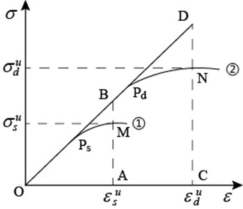
According to the similarity relation, we have:
where , ; and are the ultimate stress and strain of dynamic damage for concrete; and are the ultimate stress and strain of static damage for concrete.
In fact, for each pair of corresponding points on the static and dynamic curves, the above formula is tenable. But and are varying along with the change of strain and strain rate, which can be written in general form:
2.2. Dynamic damage constitutive model
In order to simply and approximately describe the change law of and , two basic assumptions are introduced. For any corresponding point on the dynamic curve: (1) Stress amplification coefficient is the same; (2) Stain amplification coefficient is the same. We have:
Based on many statistical results of dynamic loading tests for concrete, the calculation formulas for dynamic amplification coefficients of tension, compression stress and strain are provided by Euro-International Committee for Concrete (CEB) [23]:
where 3×10⁻⁶ s-1 is static strain rate; is dynamic strain rate, which is between 3×10⁻⁶ s-1 and 30 s-1; , ; and are static cylinder and cube compressive strength of concrete, respectively.
According to the basic assumption Eq. (2), the dynamic damage threshold strain for concrete can be obtained:
It indicates the dynamic damage threshold strain for concrete is proportional to the static condition, of which the static damage threshold strain refers to ultimate tensile strain and compression strain according to the stress states.
The dynamic damage constitutive equation for concrete can be obtained:
In order to display the damage state of lining structure in the post-processing, the second-order damage tensor is converted to a first-order damage scalar when outputting the damage results, which is applied to represent the whole damage state of element, namely .
The tensile and compressive damage evolution equations for concrete under static condition can be expressed as [24]:
where is the damage constant of concrete material.
2.3. Dynamic cracking process simulation
Without cracks, the concrete could be regarded as a linear-elastic isotropic material. For simplification, this paper assumes that the trend of crack growth is perpendicular to the direction of maximum principal strain. It should be noticed that since the compressive strength of concrete is far more than tensile strength, the damage and cracking mainly refer to tensile crack. In the calculation process, if the actual strain of concrete element exceeds the ultimate tensile strain, crack will appear in the lining. The schematic of lining cracking is shown in Fig. 2, in which refers to the direction of maximum principal strain, and it is perpendicular to the crack interface. The maximum principal stress of the cracked element will be released and stress will be redistributed. Consequently, the stiffness coefficient along the direction of maximum principal strain will be equal to zero, and the constitutive relation of the cracked element will become anisotropic, which should be corrected by the damage and cracking state of element. The stress matrix of cracked element under local coordinate system can be obtained [25]:
where:
and , are Poisson’s ratio and elastic modulus of concrete, respectively; is the residual shear coefficient, which is used to describe the residual shear capacity after concrete cracking; is the element damage variable. Through the coordinate transformation, the stress matrix of damage and cracked elements in the global coordinate system can be obtained.
Fig. 2Schematic of lining cracking
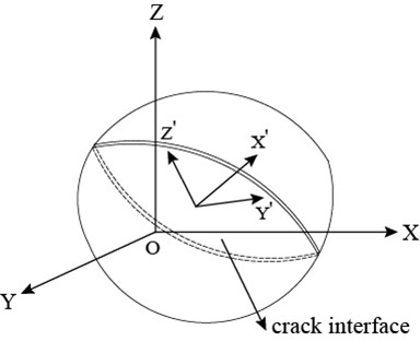
Fig. 3Combined bearing model of lining and steel
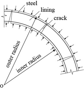
The combined bearing model of lining and steel in high pressure diversion tunnel is shown in Fig. 3. When the load is small, lining and steel work together with continuous deformation, otherwise, the bond-slip phenomenon occurs, resulting in cracks along the radial direction of tunnel. It is well known that the crack width has a close relationship with the thickness of protection layer, the spacing and strain of steel. The following formula is often used to estimate the crack width [26, 27]:
where is the maximal probability crack width; is the strain of steel; , , and are the thickness of protection layer and spacing of steel respectively.
The bond of lining and steel is a complex interaction to transfer stress and deformation. The damage variable is used to describe the change of material mechanical characteristic. When is more than zero, the lining will partly lose its force-bearing capacity, and the steel will share partial load. When cracks occur in lining, the load will be redistributed, and the strain of steel can be described by the maximum principal strain of lining element:
where is the elasticity modulus ratio of steel to lining; is the reinforcement ratio; is the maximum principal strain of lining element.
According to the Eqs. (12) and (13), the maximal probability crack width of lining elements can be estimated as follows:
3. Coupling interaction analysis model of inner water and lining
3.1. Dynamic explicit finite element method of fluid medium
In view of the horizontal seismic vibration in this paper, when performing finite element analysis aimed at the interaction system of inner water and lining structure, it can be assumed that the fluid in the limited computing area is a steady uniform flow, and mainly considering the normal interaction between fluid and structure, which almost meet the basic assumptions of fluid element based on displacement. The dynamic equation of non-viscous compressible fluid (ideal fluid) is obtained:
where the subscript 1 is the fluid medium; means the fluid density, means bulk modulus; and refer to acceleration and displacement, respectively; and are Cartesian coordinate components.
When the explicit element method is combined with multi-transmitting artificial boundary, a very little damping which is proportional to the stiffness matrix is introduced to eliminate the high frequency instability problem [28]. Meanwhile, the explicit finite element discretization equation of non-viscous compressible fluid can be written as:
where , and respectively refer to mass matrix, damping matrix and stiffness matrix of fluid medium; is external load matrix of fluid-lining coupling interface; , and are acceleration, velocity and displacement matrix of fluid medium.
From the viewpoint of stability and calculation workload, the explicit integration scheme based on time domain weighted residuals is adopted. The time domain explicit integral format [29] and the node force expression of fluid-lining coupling interface for dynamic analysis of non-viscous compressible fluid are obtained:
where the subscript refers to the node number of fluid medium, is the coordinate direction of node.
3.2. Dynamic explicit finite element method of solid medium
For lining structure and rocks, in the case of no volume force, a dynamic equation of linear elastic solid medium is obtained according to the classic linear elastic dynamics theory:
where the subscript 2 refers to lining or rock medium; and are Lame constants; is the density of lining or rock.
Discretizing the Eq. (20) with the explicit finite element method and introducing the Rayleigh damping terms can lead to the following explicit FEM equation of solid medium:
where , and respectively refer to mass matrix, damping matrix and stiffness matrix of solid medium; and respectively refer to the external load matrix of fluid-lining coupling interface and seismic load matrix of boundary.
Likewise, the explicit integration scheme based on time domain weighted residuals is adopted. The displacement and velocity responses of solid medium and node force of fluid-lining coupling interface can be expressed as:
With regard to fluid and solid medium, the following initial conditions can be introduced:
3.3. Boundary conditions of coupling interface and explicit finite element solution
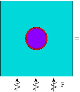
According to the mechanical properties of structure, the seismic response of diversion tunnel can be regarded as the superposition of conditional seismic response process of inner water and structure, as shown in Fig. 4. In which Fig. 4(a) is the sketch of seismic response of diversion tunnel; Fig. 4(b), 4(c) are respectively sketches of seismic response of structure and inner water; and are interaction forces of the fluid-lining coupling interface; and refer to seismic input load.
The continuity conditions of interface stresses and displacements are satisfied for ideal fluid medium and lining medium. The boundary conditions can be expressed as follows.
1) The normal stress of interface is continuous:
2) The tangential stress of interface is zero:
3) The normal displacement and velocity of interface are continuous:
where is the node number of fluid-lining coupling interface; and are normal and tangential direction of interface node.
Substituting the boundary condition equations from Eqs. (27) to (29) into the displacement and velocity Eqs. (17), (18) and (22), (23), the normal displacement and velocity of interface node of fluid and lining medium at time step can be acquired:
Substituting the normal displacement and velocity expressions of interface node into Eqs. (19) and (24), the nodal load of interface at next time step can be solved. Then substituting the nodal load expressions into Eqs. (18) and (23), the internal node velocity of fluid and lining medium at time step can be obtained.
It should be noted that this paper is just focused on the normal load of fluid-lining coupling interaction rather than the tangential load, and the normal load of interface at the initial time is the internal water pressure under the static condition.
Fig. 4Seismic response analysis model of diversion tunnel
a) Diversion tunnel
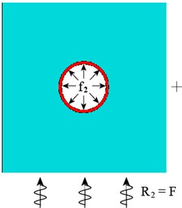
b) Lining and rocks
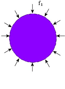
c) Inner water
4. Inner water exosmosis analysis after lining cracks
Under seismic load, concrete lining structure would enter into the damage evolution stage and eventually produce macroscopic cracks, resulting in inner water exosmosis along the cracks [30]. Because the formation time of seepage field is far more than seismic duration, studying the unsteady seepage problem under seismic load lacks practical significance. This paper just accounts for the situation of inner water exosmosis after earthquake.
It could be known from the results of permeation tests [31] that the permeability of concrete material will sharply increase with the formation and development of cracks, and it has a close relationship with the crack width. Because of the limitation of experiment condition, the fissure seepage rule [32] is based on the precondition that the fissures are smooth, flat and straight. In view of the roughness and partial contact of concrete cracks, the permeability along the propagation direction of the main crack can be calculated by the modified cubic law [33, 34]:
where and are the bulk density and dynamic viscosity factor of water respectively; is the roughness modification coefficient of crack; is the average raised height of granule in crack, which can be determined by tests; is the hydraulic diameter of crack, which is twice of the crack width.
The concrete with cracks can be regarded as an anisotropic medium. According to Darcy’s law, the basic equation of three-dimension stable seepage can be obtained as follows:
where , , are the main permeability coefficient in direction , , ; is the seepage quantity of unit volume; is the hydraulic head.
Based on the principle of FEM, the node hydraulic heads are interpolated through the interpolation principle after the seepage field is discretized. The basic equation of three-dimension stable seepage can be described as follows:
where is the seepage conductive matrix; is the nodal load matrix which is integrated at the seepage boundary.
Combining with two kinds of boundary conditions for three-dimension stable seepage, the inner water exosmosis considering lining cracks after earthquake can be solved.
5. Engineering application
5.1. Engineering background
Some hydropower station located in western Yunnan province of China is the fifth cascade hydropower plant of upper reaches of Lancang River. The diversion tunnel of the hydropower station spans 7126 m, which goes across different geological tectonic zones. The tunnel section from 2+500.00 to 2+680.00 located in the middle of water diversion system is chosen for analysis in this paper, of which the seismic intensity is up to VII. The tunnel section is designed in circular structure, with the excavation diameter 10.2 m, inner diameter 9.0 m after secondary lining, center elevation of tunnel 32.00 m, buried depth of tunnel 241.67 m and maximum inner head 135.24 m. The reinforced concrete structure is applied in the tunnel with C25 concrete, and the lining thickness is 0.6 m.
Fig. 5Complete finite element model
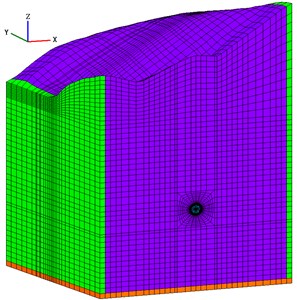
Fig. 6Local finite element model and monitoring points
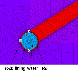
Three-dimensional finite element model of diversion tunnel including fluid, lining structure and surrounding rocks is established, which consists of 63307 nodes and 59584 hexahedron elements, and the lining and fluid element numbers are 2688 and 5264 respectively. Besides that, there is FSI of inner water and lining structure, of which the node number is 696. The model ranges along , , and -axes are 180.0 m, 180.0 m, and 321.67 m respectively. The complete finite element model of diversion tunnel is shown in Fig. 5, and the local finite element model and layout of monitoring points are shown in Fig. 6. The plane 90.0 m is chosen as the monitoring section, and point A on the vault, point B on the haunch, and point C on the inverted arch of the lining structure of monitoring section are selected as monitoring points to acquire the quantitative dynamic responses under seismic load.
It should be noted that static calculation of three-dimensional finite element should be conducted firstly to simulate the excavation and lining support of diversion tunnel in order to provide the seismic analysis with initial stress and displacement conditions. The mechanical parameters of the rock mass and lining material are shown in Table 1.
Table 1Mechanical parameters of materials
Material | Deformation modulus (GPa) | Cohesion (MPa) | Friction angle (°) | Tensile strength (MPa) | Permeability coefficient (cm∙s-1) |
Rock | 10 | 0.8 | 45 | 1.2 | 5×10⁻⁶ |
Lining | 28 | 1.8 | 40 | 1.27 | 1×10⁻⁷ |
Fluid | 2.1 | – | – | – | – |
5.2. Calculation conditions
Free field boundary condition is applied to absorb the reflection waves along the two vertical boundaries which are perpendicular to -axes, and Viscoelastic artificial boundary condition is used to absorb the incident waves from the bottom of the model[35].
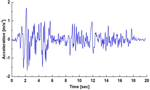
In this study, the acceleration time history curve of the wave of the 1940 EI Centro earthquake (north-south, magnitude 6.7, and maximum acceleration = 2.49 m/s2) is adopted. According to the existing codes, the peak value is adjusted to 0.17 ( is gravity acceleration), which is equivalent to the seven degree fortification criterion, and duration time is 20 s. The horizontal (direction of -axes) vibration is considered in this paper, and after pretreatment, the -acceleration time history curve which is inputted from the bottom of the limited area is shown in Fig. 7.
Fig. 7X-acceleration time history curve of input seismic wave
5.3. Calculation results and analysis
5.3.1. Displacement-time history analysis of lining structure
-displacement time curves of monitoring points of lining structure are shown in Fig. 8. The conclusions can be obtained: (1) The displacement time curve of the vault, haunch and inverted arch almost coincide; (2) -displacement reaches the maximum 7.12 cm at 2.66 s, and reaches the minimum –6.78 cm at 4.08 s; (3) The displacement reaches the wave peak or trough at the same time, indicating that various locations are in a synchronous vibration state.
By comparing with the displacement time curves of monitoring points, it can be known that the displacement of haunch is less than the vault and inverted arch when considering the hydrodynamic pressure, and the maximal differential displacement exceeds 10 mm, which seems small, but the relative deformation of 10 mm can make great influence on the mechanical properties of lining structure.
These conclusions indicate that the haunch of tunnel structure is significantly affected by the hydrodynamic pressure, which impedes the deformation of lining structure.
Fig. 8Displacement-time curves of monitoring points
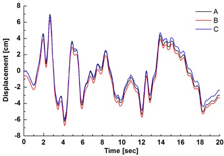
Fig. 9Maximum principal stress-time curves of monitoring points
5.3.2. Principal stress-time history analysis of lining structure
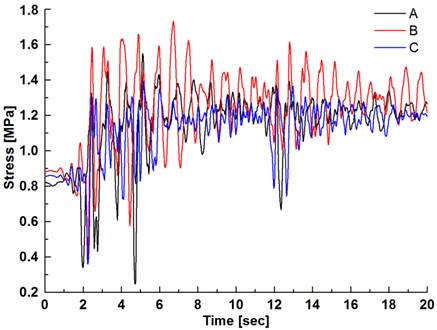
Since the compressive strength of concrete is far more than the tensile strength, the damage and failure modes of lining structure under seismic load mainly refer to tensile failure. This paper is focused on the change laws of maximum principal stresses of monitoring points. The maximum principal stress-time curves of monitoring points of lining structure are shown in Fig. 9, which indicate the following: (1) The maximum principal stress of lining structure is up to 0.8-0.9 MPa under the initial hydrostatic pressure and seismic load; (2) The maximum principal stress quickly increases, and gradually exceeds the tensile strength of concrete, in which the haunch of lining structure is remarkably influenced, leading to great stress increment; (3) The hydrodynamic pressure has a significant influence on the stress state of lining structure, and it is of great importance in the anti-earthquake design of tunnel to consider the coupling interaction of inner water and lining structure under seismic load.
5.3.3. Damage and cracking analysis of lining structure
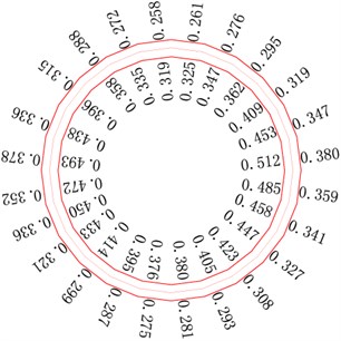
The dynamic damage and cracking model of concrete lining structure proposed in this paper is applied to simulate the damage and cracking process under seismic loading, and damage coefficient and maximal crack width distribution of lining structure at the monitoring section are shown in Fig. 10 and Fig. 11 (unit: mm).
It could be seen from Fig. 10 that under the earthquake and hydrodynamic pressure, the maximum principal stress of lining structure gradually exceeds the tensile strength of concrete, and damage and cracking of lining structure occur and develop gradually from the haunch to each side. Since lining structure mainly refers to elastic deformation under seismic load, hydrodynamic pressure becomes the key factor to cause the damage and cracking. Because the haunch of tunnel structure is remarkably influenced by earthquake and hydrodynamic pressure, causing serious damage, which gradually expands to both sides. In addition, the damage state of inner lining is much more serious than the outer layer, which indicates the parts with direct contact to inner water suffer more serious damage.
We can come to the conclusions from Fig. 11 that with the lining structure entering into damage evolution stage, cracking failure produces accordingly, and the maximal crack width distribution law is consistent with the damage coefficient. The maximal crack width at the monitoring section is up to 0.25-0.5 mm, in which the haunch has the maximal crack width, up to 0.5 mm, and expanding to the vault and inverted arch. By comparing the crack width of inner and outer lining structure, it can be seen that inner lining is significantly greater than the outer for the serious influence of hydrodynamic pressure, which reveals that the direct interaction with inner water would make great influence on lining structure, and it is the weak link of seismic design for diversion tunnel.
Fig. 10Damage coefficient distribution of lining
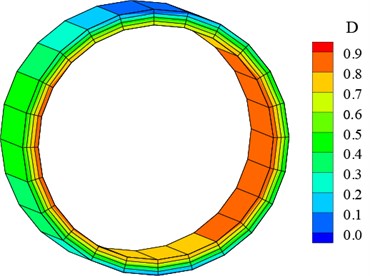
Fig. 11Maximal crack width distribution of lining
5.3.4. Inner water exosmosis analysis after lining cracks
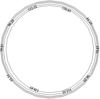
According to the three-dimensional seepage field analysis, the distribution of pressure head isolines of lining structure at the monitoring section is shown in Fig. 12. The isolines are distributed densely in the lining, and the value decreases quickly from the inner layer to the outer. Meanwhile, the distribution of the isolines in the inner layer is sparser than the outer layer, which implies that the crack width of the inner layer is bigger. Consequently, the hydraulic gradient increases from the inner layer to the outer in the lining. Since the lining structure of haunch and inverted arch suffers serious damage, leading to great increment of permeability coefficient, and resulting in the decrease of hydraulic gradient and sparser distribution of pressure head isolines than any other parts.
Furthermore, because of the damage and cracking of lining structure, inner water exosmosis makes the surrounding rocks bear more water pressure. It can be seen from Fig. 12 that the pressure head borne directly by surrounding rocks is up to 63.54 m, which accounts for about 47 % of inner head, and would greatly affect the stability of surrounding rocks.
Fig. 12Distribution of pressure head isolines of lining structure at the monitoring section
6. Conclusions
Based on the seismic response mechanism of concrete lining structure in high pressure diversion tunnel, a dynamic explicit finite element numerical simulation method considering the coupling interaction of lining and inner water is presented. Taking the dynamic damage and cracking process of concrete lining structure under seismic load into account, the inner water exosmosis process with lining cracks is analyzed. A diversion tunnel of some hydropower station is chosen as an engineering project to analyze the seismic response. We can reach the following conclusions.
1) The displacement time curves of monitoring points are consistent with the input wave, and various parts of diversion tunnel are in a synchronous vibration state. The displacement of haunch is obviously less than the vault and inverted arch due to the influence of hydrodynamic pressure.
2) Under seismic load and hydrodynamic pressure, the maximum principal stress quickly increases, and gradually exceeds the tensile strength of concrete, in which the haunch of lining structure is remarkably influenced, leading to great stress increment and serious damage.
3) The lining structure mainly enters into the stage of damage and cracking, in which the haunch is greatly affected, resulting in greater damage coefficient and crack width, and gradually extension to each side. The inner lining directly interacting with fluid is the weak link of seismic design for diversion tunnel.
4) Inner water exosmosis occurs after lining cracks. Affected by the distribution of crack width, hydraulic gradient is smaller and the distribution of pressure head isolines is sparser on the haunch. Inner water exosmosis makes the surrounding rocks bear more water pressure, and it would affect the stability of surrounding rocks.
References
-
Kazuhide Y., Yoshiyuki K. Historical earthquake damage to tunnels in Japan and case studies of railway tunnels in the 2004 Niigataken-Chuetsu Earthquake. QR of RTRI, Vol. 48, Issue 4, 2007, p. 136-141.
-
Wang W. L., Wang T. T., Su J. J., et al. Assessment of damage in mountain tunnels due to the Taiwan Chi-Chi Earthquake. Tunneling and Underground Space Technology, Vol. 16, 2001, p. 133-150.
-
Li T. B. Damage to mountain tunnels related to the Wenchuan earthquake and some suggestions for a seismic tunnel construction. Bulletin of Engineering Geology and the Environment, Vol. 71, 2012, p. 297-308.
-
Wang Z. Z., Gao B., Jiang Y. J., et al. Investigation and assessment on mountain tunnels and geotechnical damage after the Wenchuan earthquake. Technological Sciences, Vol. 25, Issue 2, 2009, p. 546-558.
-
Tedesco J. W., Powell J. C., Allen R. C., et al. A strain-rate-dependent concrete material model for ADINA. Computers and Structures, Vol. 64, Issue 5, 1997, p. 1053-1067.
-
Winnicki A., Cichon C. Plastic model for concrete in plane stress state. Journal of Engineering Mechanics, Vol. 124, Issue 6, 1998, p. 591-602.
-
Xiao S. Y., Li H. N., Du R. Q., et al. Four-parameter dynamic constitutive model of concrete. Journal of Harbin Institute of Technology, Vol. 38, Issue 10, 2006, p. 1754-1757.
-
Pandey A. K., Kumar R., Paul D. K., et al. Strain rate model for dynamic analysis of reinforced concrete structures. Journal of Structural Engineering, Vol. 132, Issue 9, 2006, p. 1393-1401.
-
Shkolnik I. K. Influence of high strain rates on stress-strain relationship, strength and elastic modulus of concrete. Cement and Concrete Composites, Vol. 30, 2008, p. 1000-1012.
-
Li Q. B., Zhang C. H., Wang G. L. Dynamic damage constitutive model of concrete in uniaxial tension and compression. Journal of Wuhan Institute of Hydraulic and Electric Engineering, Vol. 12, 1994, p. 55-60.
-
Wang J. T., Du X. L., Zhao C. G., et al. Explicit finite element scheme for dynamic analyses of wave propagation in multi-layered media. Chinese Journal of Rock Mechanics and Engineering, Vol. 22, Issue 1, 2003, p. 75-79.
-
Wang J. T., Du X. L., Zhao C. G. Explicit finite element method for dynamic analyses of fluid-saturated porous solid. Chinese Journal of Rock Mechanics and Engineering, Vol. 21, Issue 8, 2002, p. 1119-1103.
-
Wang T. T., Yang C. H., Yan X. Z., et al. Dynamic response of underground gas storage salt cavern under seismic loads. Tunnelling and Underground Space Technology, Vol. 43, 2014, p. 241-252.
-
Hashemi S., Saadatpour M. M., Kianoush M. R. Dynamic behavior of flexible rectangular fluid containers. Thin-Walled Structures, Vol. 66, 2013, p. 23-28.
-
Du X. L., Wang J. T. Seismic response analysis of arch dam-water-rock foundation systems. Earthquake Engineering and Engineering Vibration, Vol. 3, Issue 2, 2004, p. 283-288.
-
Bouaanani N., Renaud S. Effects of fluid–structure interaction modeling assumptions on seismic floor acceleration demands within gravity dams. Engineering Structure, Vol. 67, 2014, p. 1-8.
-
Nateghi R., Kiany M., Gholipouri O. Control negative effects of blasting waves on concrete of the structures by analyzing of parameters of ground vibration. Tunnelling and Underground Space Technology, Vol. 24, Issue 6, 2009, p. 508-515.
-
Cheng X. S., Xu W. W., Yue C. Q., et al. Seismic response of fluid-structure interaction of undersea tunnel during bidirectional earthquake. Ocean Engineering, Vol. 75, 2014, p. 64-70.
-
Song Y. P. Dynamic Constitutive Relation and Failure Criterion for Concrete. Academic Press, Beijing, China, 2013, p. 240-288.
-
Zhou X. Q., Hao H. Modelling of compressive behavior of concrete-like materials at high strain rate. International Journal of Solids and Structures, Vol. 45, 2008, p. 4645-4661.
-
Bischoff P. H., Perry S. H. Compressive behavior of concrete at high strain rates. Materials and Structures, Vol. 24, 1991, p. 425-450.
-
Brooks J. J., Al-Samarie N. H. Influence of Rate of Strength on Tensile Stress-Strain Behavior Concrete. Fracture of Concrete and Rock, Elsevier Science Publisher, 1989.
-
Chen J. Y., Hu Z. Q., Lin G. Seismic analysis of arch dam with joints based on a new strain-rate-dependent plastic damage model. Chinese Journal of Computational Mechanics, Vol. 24, Issue 1, 2004, p. 45-49.
-
Zhang Z. G., Xiao M., Chen J. T. Simulation of earthquake disaster process of large-scale underground caverns using three-dimensional dynamic finite element method. Chinese Journal of Rock Mechanics and Engineering, Vol. 30, Issue 3, 2011, p. 509-522.
-
Su K., Wu H. G. Nonlinear finite element analysis of reinforced concrete lining of hydraulic tunnels. Rock and Soil Mechanics, Vol. 26, Issue 9, 2005, p. 1485-1490.
-
Yuan J. L., Xiao M., Fu Z. H. Numerical analysis on lining structure of restricted cylindric surge chamber in rock masses with steep obliquity. Chinese Journal of Rock Mechanics and Engineering, Vol. 23, Issue 8, 2004, p. 1296-1300.
-
Chen J. T., Yang Y., Ye C., et al. Three-dimensional numerical analysis of compound lining in complex underground surge-shaft structure. Mathematical Problems in Engineering, 2015, p. 387379.
-
Liao Z. P. An Introduction to Wave Motion Theories in Engineering. Academic Press, Beijing, China, 2002, p. 65-322.
-
Wang J. T., Du X. L. An explicit difference method for dynamic analysis of a structure system with damping. Engineering Mechanics, Vol. 19, Issue 3, 2002, p. 109-111.
-
Zhao Y. L., Cao P., Wang Y. X., et al. Coupling model of seepage-damage-fracture in fractured rock masses and its application. Chinese Journal of Rock Mechanics and Engineering, Vol. 27, Issue 8, 2008, p. 1634-1643.
-
Gerard B., Breysse D., Ammouche A., et al. Cracking and permeability of concrete under tension. Materials and Structures, Vol. 29, Issue 3, 1996, p. 141-151.
-
Xiong X. B., Zhang C. H., Wang E. Z. A review of steady state seepage in a single fracture of rock. Chinese Journal of Rock Mechanics and Engineering, Vol. 28, Issue 9, 2009, p. 1839-1847.
-
Wu Y. Q. Types of rock mass structure and hydromechanical models in rock mass. Chinese Journal of Rock Mechanics and Engineering, Vol. 19, Issue 6, 2000, p. 687-691.
-
Bian K., Xiao M., Chen J. T. Study on coupled seepage and stress fields in the concrete lining of the underground pipe with high water pressure. Tunnelling and Underground Space Technology, Vol. 24, 2009, p. 287-295.
-
Zhang Z. G., Chen J. T., Xiao M. Artificial boundary setting for dynamic time-history analysis of deep buried underground caverns in earthquake disaster. Disaster Advances, Vol. 5, Issue 4, 2012, p. 1136-1142.
About this article

