Abstract
The most important thing in applying mass type dampers including Liquid Column Vibration Absorber (LCVA) is tuning its natural frequency to an optimum value which is a function of the natural frequency of the building and the mass ratio of damper to the building. However, exact prediction of the natural frequency of the building at design stage is very difficult especially for concrete buildings. Thus, continuous updating of the target frequency and correction of the design of the damper based on field measurement is necessary. In this paper, application of LCVAs to mitigate the wind-induced vibration of 64-story residential buildings is presented. The LCVA were designed to have adjustable dimension for vertical column to take the advantage of ease tuning and wide frequency range. For updating of initial design, the tuning and performance assessment of LCVA several tests and measurement were carried out. The ambient vibration measurement of a partially completed building and a completed building without water in LCVA was performed and final values of the width of vertical column and the height of water were determined from the system identification results based on the collected acceleration data. In addition, ambient vibration measurement of buildings with LCVA water was performed and the system identification results indicated that the apparent damping ratio due to LCVA was increased about 3.13 to 3.89 times.
1. Introduction
The increasing height of tall buildings in these days often requires supplementary damping systems for occupant comfort in windy condition. The tuned mass damper (TMD), tuned liquid damper (TLD), and tuned liquid column damper (TLCD), which are typical types of such supplementary damping systems, have been frequently researched and installed in practice for the mitigation of wind-induced motions [1-3]. Especially, the use of TLD and TLCD is increasing because of their cheap installation cost and ease of maintenance [4, 5].
More recently, a liquid column vibration absorber (LCVA) has attracted significant attention from both researchers and engineers [6, 8]. The LCVA is similar to the TLCD in that they both utilize the motion of liquid in the columns of a U-shaped container to counteract the external forces acting on the structure. However, unlike the TLCD, the LCVA has different dimensions for the width of columns and depth of horizontal tank, thus, it has the advantages of easy tuning and wide natural frequency range. Capability of adjusting the natural frequency is a major merit of LCVA comparing with the TLCD, since the accurate prediction of natural frequency via analytical model is generally difficult especially for the reinforced concrete buildings. It is reported that the measured natural frequencies of actual buildings increase by about 20 % compared to those of an analysis model [9].
However, researches on the LCVA have focused on the numerical analysis or experimental verification of performance using small scale models. Because the governing equation of the LCVA is derived from the equilibrium of a liquid in U-shaped column without considering the variation of velocity and separation of water flow, it does not represent the actual behavior of the liquid. Further, there exists a difference of dynamic characteristics between a scale model and a full-scale one due to size effect.
In this paper, assessment of effectiveness of an LCVA actually installed at 64-story residential buildings is presented. First, a brief description of the buildings is presented followed by the initial design of the LCVA’s. Then, a counter measure to cope with the difference between the actual frequency of the completed building and the initial prediction from a finite element (FE) analysis is illustrated. Finally, the performance evaluation of LCVA is presented based on the ambient vibration measurement of the building with and without LCVA water.
2. Building description
The buildings used in this study are the part of the Songdo First World building complex located in Incheon, Korea that includes four identical towers and several midrise buildings as shown in Fig. 1. The four towers that rise 237 m above street level consist of 64-story residential floors, a three-floor basement for parking, and three mechanical penthouse floors. The towers have a flat slab system whose gravitational loads are carried by a concrete core with varying thickness from 1200 mm to 600 mm and outer columns with maximum span of 6.8 m. The lateral resistance against wind load is provided mainly by the concrete core and two reinforced concrete outrigger walls located on the 33rd and 60th floor. The aspect ratio of towers is 237/33.8 = 7.0 causing susceptibility to wind-induced vibration.
Fig. 1Songdo First World
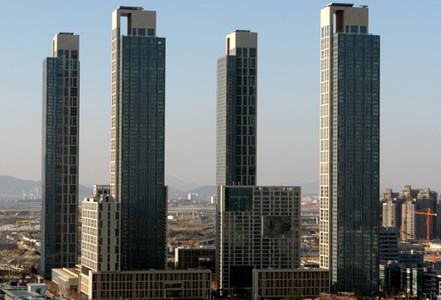
Fig. 2Acceleration prediction result from the wind tunnel test
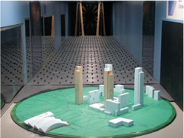
a) Wind tunnel test
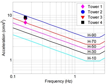
b) Predicted peak acceleration
Thus, the wind tunnel test using the high frequency force balance technique was carried out to estimate the wind-induced acceleration at the top occupied floor at the design stage (Fig. 2(a)). In the estimation, the wind speed of 1-year return period was used and the wind statistics for the wind tunnel test were based on surface wind measurement taken at Kimpo International Airport and Incheon Weather Station between 1950 and 1997.
The peak accelerations were determined based on the assumed overall damping ratio of 2.0 % critical for 1 year return period wind loading. Although the exact damping value of the towers is unknown, a 2.0 % is a typical value commonly used for the evaluation of vibration of concrete towers subjected to wind loading [10]. In Fig. 2(b), the predicted peak accelerations for four towers are compared with AIJ-2004 criteria [11]. The AIJ-2004 criteria provide five curves which indicate different perception probability as a percentage. The curve of H-10 means 10 % of people can perceive the vibration, and thus indicates the most severe criteria. The curve of H-90 is on the opposite side. While the target acceleration range for the towers is set to H-50, the wind tunnel test results showed that the acceleration range of all towers lie between the H-70 and H-90, Accordingly, it was decided to adopt the LCVA system in four towers to alleviate the vibration range.
3. Preliminary design of LCVA
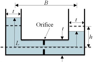
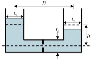
Fig. 3 shows schematic drawing of the TLCD and LCVA. In the figure, and indicate the central distance between the vertical columns and the water height measured from the center of horizontal column, respectively. For TLCD, is water tube length and is the width of water tube. For LCVA, and are the width of vertical columns and horizontal column, respectively.
Fig. 3Schematic drawings of TLCD and LCVA
a) TLCD
b) LCVA
Both of TLCD and LCVA utilize the motion of the liquid in a U-shaped container to counteract the forces acting on the structure. The LCVA as well as the TLCD may have orifices or louvers to increase the energy dissipation by providing resistance during the passage of the liquid. However, unlike TLCD that has constant rectangular section through the vertical and horizontal columns, the LCVA has different section areas for vertical and horizontal part of water tank as shown in Fig. 3(b). The natural frequency of TLCD is estimated using the water tube length [12]. Similarly, the natural frequency of an LCVA is estimated using the effective water tube length as in Eq. (1) [13]:
where is the natural frequency and is the gravitational acceleration. is the ratio of to ().
Eq. (1) was derived from theoretical observation considering the equilibrium of a liquid in U-shape tank. However, it does not serve exact results because the variation of velocity and separation of water flow near the transition of vertical and horizontal part was ignored [14].
In order to meet the target criteria for wind-induced motion, two perpendicular LCVAs that will be placed on the 66th floor was designed (Fig. 4). Preliminary design of LCVAs was performed assuming that the natural frequencies of the building are 0.181 Hz and 0.164 Hz in - and -directions, respectively, which are the predicted values using the FE model at design stage. From the FE model, the generalized mass in each direction was 34,908 ton and 36,365 ton, respectively. To decrease the current acceleration level of 6.9-9.1 cm/sec2 to below 5.375 cm/sec2 (H-50), the mass ratios of two perpendicular LCVAs were set to 0.59 % and 1.18 % in - and -directions, respectively.
Two adjustable louvers were provided in the vicinity of the intersection of the vertical and the horizontal part of the water tank. The purpose of the louvers is to achieve the desired damping force in an LCVA by creating turbulence flow. The louvers block 80 % of the cross section when it was fully closed.
Fig. 4Placement of LCVA on 66th floor
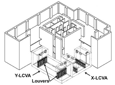
Fig. 5 shows preliminary design of the LCVA in y-direction of building (Y-LCVA). The Y-LCVA is 7.2 m wide, 20.2 m long and 7.3 m tall. The size of the -direction LVCA (X-LCVA) is smaller than the Y-LCVA. The width of vertical part of the Y-LCVA can be changed from 2 to 4 m as shown in Fig. 5. Because the natural frequency of the LCVA is a function of the ratio of to as in Eqs. (1) and (2), the natural frequency of this LCVA can be adjustable to an optimum value between 0.134 Hz to 0.180 Hz, which are about 82 %-110 % of initially estimated natural frequency of fundamental mode in -direction, 0.164 Hz. Mass of water that participates in controlling the motion of the structure also changes with the change of vertical column width from 418 to 437 ton for the Y-LCVA and 184 to 225 ton for X-LCVA.
Fig. 5Dimension of LCVA
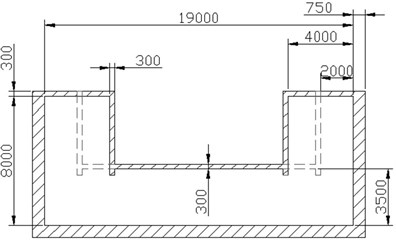
a) TLCD Section of Y-LCVA (in mm)
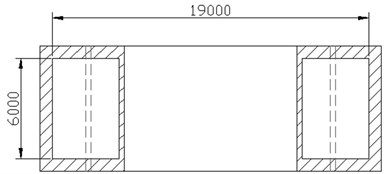
b) Plan of Y-LCVA (in mm)
4. Preliminary tuning of LCVA: ambient vibration measurement of a partially completed building
After finishing concrete casting of the 64th floor, a field measurement was performed to determine the width of vertical part of LCVA. The timing of the field measurement was selected such that the width of vertical part was addressed before the form work started for LCVAs located on the 66th floor. The measured natural frequencies of the partially completed building are compared to those of FE model with same configuration are summarized in Table 1. It can be noted from Table 1 that the actual building is stiffer than the FE analyzed one with natural frequency errors of 4.83 % and 3.70 % in - and -directions, respectively.
Table 1Measured and FE analyzed natural frequencies of a partially completed building
Description | -direction (weak direction) | -direction (strong direction) |
FE analyzed natural frequency | 0.212 Hz | 0.238 Hz |
Measured natural frequency | 0.220 Hz | 0.249 Hz |
Error | +3.70 % | +4.83 % |
The initial FE model was updated reflecting the comparison result presented in Table 2 and the modal analysis was performed again. The FE model updating was carried by altering the cracked stiffness of the concrete core wall and outer columns and the effective width of flat slab. The corresponding natural frequencies of the updated FE model of entire building along with initial ones are presented in Table 2.
Table 2Natural frequencies of updated FE model of entire building
Description | -direction (weak direction) | -direction (strong direction) |
Initial FE model | 0.164 Hz | 0.181 Hz |
Updated FE model | 0.171 Hz (+4.27 %) | 0.190 Hz (+4.97 %) |
The updated natural frequencies of the building in Table 2 were used to determine the final width of the vertical part of LVCA. Using the corrected estimation, the width of vertical part of LCVA was calculated to be 2.31 m for both X- and Y-LCVAs. Considering that the designs of four towers were identical and the difference of measured natural frequencies was negligible, the width of vertical part of LCVA in every tower was determined to be same.
5. Final tuning of LCVA: ambient vibration measurement of a completed building
The as-built frequencies of the completed building may also differ from ones obtained using the updated FE model due to the effects of non-structural members that were not considered in the analytical model. Once the dimensions of the LCVAs are fixed, their frequencies can be fine-tuned by altering the nominal water levels only. For this purpose, ambient vibration tests of completed buildings with empty LVCA were performed once after the construction was completed.
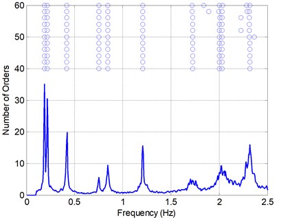
Fig. 6 shows the example acceleration time histories of the completed building with empty LCVA. All data was collected at 200 Hz sampling frequency. During the measurement, the building was subjected to a light wind. One of time domain system identification techniques referred to as Stochastic Subspace Identification (SSI) technique [15] was used for identification of natural frequency and damping ratio. Fig. 7 shows the power spectral density (PSD) of measured acceleration data and stabilization chart for SSI. The stabilization chart was constructed in order to distinguish spurious modes from the identified mode. Table 3 summarizes the identified natural frequencies and damping ratios in each direction.
Table 3Results of ambient vibration measurement of a completed building with empty LCVA
Dynamic characteristics | -direction (weak direction) | -direction (strong direction) |
Frequency | 0.189 Hz | 0.215 Hz |
Damping ratio | 0.47 % | 0.56 % |
It can be noticed from Table 3 that the natural frequencies of the completed building were greater 10.5 % and 13.2 % in - and -directions, respectively, than the updated ones presented in Table 2. This is seemingly because of effects of non-structural members which are not considered in the analysis model. The natural frequencies of the completed building in Table 3 were greater 15.2 % and 18.8 % in in - and -directions, respectively, than the initially predicted ones.
Fig. 6Sample acceleration time histories of ambient vibration of a completed building with empty LCVA
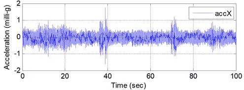
a)-direction
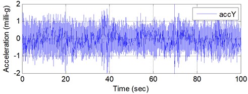
b)-direction
Fig. 7Stabilization chart and PSD of ambient vibration of a completed building with empty LCVA
It can also be noted from Table 3 that the identified damping ratios are smaller than 2.0 % which was assumed for estimation of peak accelerations from the wind tunnel test results. This is because the damping ratios in Table 3 were obtained from ambient vibration records during a light wind was exerted. Considering the fact that the damping ratio generally increases as the magnitude of response increases [16, 17], damping ratios of this building will be increased under much stronger wind of 1 year return period.
Based on the natural frequencies obtained from the ambient vibration measurement of the completed building, the water level was determined such that the natural frequencies of LCVA are about 96.8 % of those of the buildings according to optimal frequency formal for secondary mass type dampers [18]. Further, the water level was determined considering the peak movement of water in the vertical part of LCVA. This is because the water level of the vertical part cannot be lower than the water level of the horizontal part when the peak movement occurs. The finally determined water level was 3.9 m in Y-LCVA and 2.5 m in X-LCVA.
6. Performance assessment of LCVA
A free oscillation test and the ambient vibration measurement were performed to verify the effectiveness of LCVAs. The free oscillation test was carried out by depressurizing the air in water tank so that the water in the vertical part of LCVA slowly moved up one side from the equilibrium position while the water in the opposite vertical part moved down. Once the water movement reached at 400 mm, the air was supplied rapidly so that the water level dropped quickly enough to induce the movement of the building. Fig. 8 shows the measured water level of Y-LCVA and the acceleration time history of the building in -direction obtained from the free oscillation test. The corresponding PSD of the acceleration record is presented in Fig. 9.
Fig. 8Measured water level and acceleration from the free oscillation test of Y-LCVA
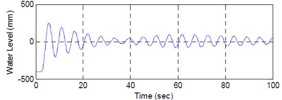
a) Time history of water level in Y-LCVA
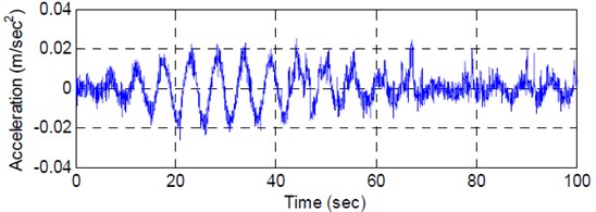
b) Acceleration time history in -direction
Fig. 9PSD of y-direction acceleration of the building measured from the free oscillation test
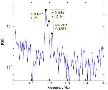
It can be seen from Fig. 8 that the movement of water in LCVA is enough to force the movement of the building of about 0.02 m/sec2. It can also be noticed from Fig. 9 that the peak of PSD split into two peaks near the natural frequency of building of 0.189 Hz in -direction. Consequently, it may indicate that the tuning of LCVA was done well enough to have interaction between the building and damper.
The identified natural frequencies and damping ratios from the free oscillation test are summarized in Table 4 [19]. It can be noticed that the identified natural frequency of the building is very close to one presented in Table 3. Also, the tuning ratio of the LCVA natural frequency to building natural frequency is 0.9644 which is almost identical to the target tuning ratio of 0.968. Further, it can be noted from Table 4 that the damping ratio of the building was increased about 3 times compared to one obtained from the ambient vibration measurement with empty LCVA.
Table 4Identified natural frequencies and damping ratios from the free oscillation test in y-direction
Natural frequency | Damping ratio | |
LCVA | 0.1788 Hz | 3.65 % |
Building | 0.1854 Hz | 1.50 % |
The ambient vibration measurement was also performed again after filling LCVAs with required amount of water. The PSD result and stabilization chart are constructed as in Fig. 10. Table 5 summarizes the identified natural frequency and damping ratios.
Fig. 10Stabilization chart and power spectral density of ambient vibration of a building with LCVA water
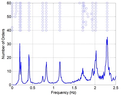
Table 5Results of ambient vibration measurement of a completed building with LCVA water
Dynamic characteristics | -direction (weak direction) | -direction (strong direction) |
Frequency | 0.188 Hz | 0.212 Hz |
Damping ratio | 1.47 % | 2.18 % |
By comparing results summarized in Table 5 with ones in Table 4, it can be seen that the natural frequency and damping ratio are identified from the ambient vibration measurement are very close to ones identified from the free oscillation test. When results of Table 5 are compared with those of Table 3, it can be seen that damping ratios were increased 3.13 times and 3.89 times in - and -directions, respectively after filling the LCVA with water.
7. Conclusion
The design and construction of an LCVA installed in a 64-story residential building for mitigation of wind-induced motion is presented in this paper. Because LCVA has different dimensions for vertical and horizontal portions of container, it has the benefits of easy tuning and wide natural frequency range. In order to adopt these benefits, LCVAs are designed to have adjustable inner vertical wall dimension. The final location of inner vertical wall dimension was determined based on the on-site measurement of the partially completed building and the consequent updating of analytical model. The depth of water in LCVA was determined based on the results of ambient vibration measurements and forced free oscillation tests.
The shaking table test and scale mode test using a 1/20 scale model were performed for the evaluation of natural frequency and control performance of the LCVA. Further, the system identification method was applied to the measured ambient vibration of buildings with and without LCVA water in order to evaluate the damping increase due to the installation of LCVA. The results of scale model test and the system identification of buildings with and without LCVA water indicate that an LCVA reduces the wind-induced acceleration of the building considerably.
References
-
Housner G. W., Bergman L. A., Caughey T. K., Chassiakos A. G., Claus R. O., Masri S. F., Skelton R. E., Soong T. T., Spencer B. F., Yao J. T. P. Structural control: past, present, and future. Journal of Engineering Mechanics, Vol. 123, Issue 9, 1997, p. 897-971.
-
Rana R., Soong T. T. Parametric study and simplified design of tuned mass dampers. Engineering Structures, Vol. 30, Issue 3, 1998, p. 193-204.
-
Kang N., Kim H., Choi S., Jo S., Hwang J.-S., Yu E. Performance evaluation of TMD under typhoon using system identification and inverse wind load estimation. Computer-Aided Civil and Infrastructure Engineering, Vol. 27, Issue 6, 2012, p. 455-473.
-
Kim H., Adeli H. Wind-induced motion control of 76-story benchmark building using the hybrid damper-TLCD system. ASCE Journal of Structural Engineering, Vol. 131, Issue 12, 2005, p. 1794-1802.
-
Tse K. T., Kwok K. C. S., Tamura Y. Performance and cost evaluation of a smart tuned mass damper for suppressing wind-induced lateral-torsional motion of tall structures. Journal of Structural Engineering, Vol. 138, Issue 4, 2012, p. 514-525.
-
Hitchcock P. A., Kwok K. C. S., Watkins R. D. 1997. Characteristics of liquid column vibration absorbers (LCVA)-I. Engineering Structures, Vol. 19, 2, p. 126-134.
-
Chang C. C., Hsu C. T. Control performance of liquid column vibration absorbers. Engineering Structures, Vol. 20, Issue 7, 1998, p. 580-586.
-
Matteo A. D., Iacono F. L., Navarra G., Pirrotta A. Direct evaluation of the equivalent linear damping for TLCD systems in random vibration for pre-design purposes. International Journal of Non-Linear Mechanics, Vol. 63, 2014, p. 19-30.
-
Fukuwa N., Nishizaka R., Yagi S., Tanaka K., Tamura Y. Field measurement of damping and natural frequency of an actual steel-framed building over a wide range of amplitudes. Journal of Wind Engineering and Industrial Aerodynamics, Vol. 59, Issues 2-3, 1996, p. 383-392.
-
7-10 Minimum Design Loads for Buildings and Other Structures. American Society of Civil Engineers (ASCE), 2010.
-
Guidelines for the Evaluation of Habitability to Building Vibration. Architectural Institute of Japan (AIJ), Tokyo, Japan, 2004.
-
Sakai F., Takaeda S., Tamaki T. Tuned liquid column damper – new type device for suppression of building vibrations. Proceedings of International Conference on Highrise Buildings, Nanjing, China, 1989, p. 926-931.
-
Chang C. C., Qu W. L. Unified dynamic absorber design formulas for wind-induced vibration control of tall buildings. The Structural Design of Tall Buildings, Vol. 7, Issue 2, 1998, p. 147-166.
-
Lee S. K., Lee H.-R., Min K.-W. Experimental verification on nonlinear dynamic characteristic of a tuned liquid column damper subjected to various excitation amplitudes. The Structural Design of Tall and Special Buildings, Vol. 21, Issue 5, 2012, p. 374-388.
-
Peeters B. De Roeck G. Reference-based stochastic subspace identification for output-only modal analysis. Mechanical Systems and Signal Processing, Vol. 13, Issue 6, 1999, p. 855-878.
-
Tamura Y. Amplitude dependency of damping in buildings and critical tip drift ratio. International Journal of High-Rise Buildings, Vol. 1, Issue 1, 2012, p. 1-13.
-
Aquino R. E. R., Tamura Y. On stick-slip phenomenon as primary mechanism behind structural damping in wind-resistant design applications. Journal of Wind Engineering and Industrial Aerodynamics, Vol. 115, 2013, p. 121-136.
-
Den Hartog J. P. Mechanical Vibrations. McGraw-Hill, New York, 1956.
-
Cho B.-H., Jo J.-S., Joo S.-J., Kim H. Dynamic parameter identification of secondary mass dampers based on full-scale test. Computer-Aided Civil and Infrastructure Engineering, Vol. 27, Issue 3, 2012, p. 218-230.
About this article

This work was supported by the National Research Foundation of Korea (NRF) Grant funded by the Korean Government (MSIP) (NRF-2010-0023976).
