Abstract
In this paper, two types of seismic retrofitting methods for reinforced concrete frames were suggested and examined through the cyclic loading tests: one is to insert a steel frame to existing partially masonry infilled concrete frame of the building after removing masonry from the concrete frame and the other is to adhere waved steel panels to the existing masonry fully infilled concrete frame. In order to evaluate validity of the suggested methods in seismic performance, five specimens were manufactured and tested: a bare concrete frame, a partially masonry infilled concrete frame, a masonry infilled concrete frame, a steel frame inserted concrete frame, and a waved steel panel adhered concrete frame. Compared were crack pattern, failure mode, load-displacement relation, ductility, stiffness and energy dissipation capacity. The specimens retrofitted with the inserted steel frame showed a maximum load approximately twice that of the partially masonry infilled frame, and the specimen retrofitted with the adhered waved steel panel showed a maximum load approximately twice that of the masonry fully infilled frame.
1. Introduction
Conventional reinforced concrete buildings without seismic design are usually designed only considering the gravity load. These buildings pose serious risks of damage or collapse because they lack the strength, stiffness, and ductility needed to survive earthquakes. Seismic retrofits of conventional reinforced concrete buildings aim to improve their strength, stiffness, and ductility against seismic loads. According to the research results of Hashemi and Mosalam [1], infill walls improve the stiffness of a reinforced concrete frame approximately four times, and improve the damping coefficient at least 4-6 % and up to 12 %. However, that effect is meaningful only when the frame and masonry behave identically. When a crack occurs in the masonry due to increasing seismic load, a brittle fracture could occur in the masonry. Anil and Altin [2] evaluated the behavior of a reinforced concrete frame with various heights and widths of the infill walls. Altin et al. [3] conducted research on reinforced concrete frames with infill walls utilizing CFRP bracing with respect to cyclic loads. In this study, seismic retrofitting methods for masonry infilled concrete frames are proposed and examined. Cyclic loading experiments were conducted with a bare frame, partially masonry infilled frame, masonry fully infilled frame, a steel frame inserted concrete frame, and wave steel panel adhered concrete frame. For these methods, the test results were analyzed in terms of maximum load, ductility ratio, and energy dissipation.
2. Experimental program
2.1. Retrofitting methods
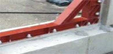
The proposed methods in this study are to insert a wide-flange shaped steel beam frame in the in-plane of a reinforced concrete frame after removing partially masonry from the concrete frame and to adhere waved steel panels to a masonry fully infilled wall without removing the masonry from the concrete frame. The inserted wide-flange shape steel beam frame enhances the strength and stiffness of beam-column joints and columns. Improvements in strength, ductility, and energy dissipation are expected from this method. As illustrated in Fig. 1, a wide-flange shape steel frame is composed of horizontal and vertical members, a brace to maximize the lateral resistance of the beam-column joints, and a plate to prevent the buckling of the frame. Fig. 2 illustrates the installation process of the wide-flange shape steel beam frame. Holes are drilled in the reinforced concrete frame for the installation of the wide-flange shape steel beam frame. After the drilling, the steel frame is attached to the reinforced concrete frame with chemical anchors and the anchored parts are finished with a sealant. Then epoxy is applied along the steel frame.
Fig. 1Wide-flange shape steel beam frame
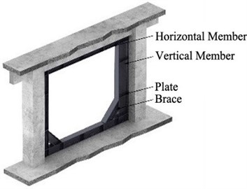
Fig. 2Installation of wide-flange shape steel beam frame to concrete frame
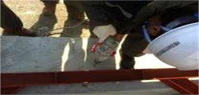
a) Drilling of holes in concrete

b) Insert of anchor

c) Injection of sealant
d) Application of epoxy
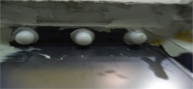
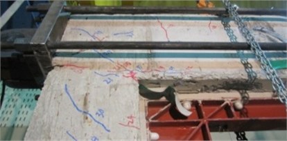
The other retrofitting method employing waved steel panels is intended to prevent the brittle fracture of a masonry wall due to separation of the masonry from the concrete frame after crack developments in the frame and masonry wall. As shown in Fig. 3, a wave panel has the shape of a bent panel and consists of protruded parts and flat parts. The flat part of the panel is adhered to the masonry wall. The process for installing waved steel panels is illustrated in Fig. 4. The flat portions of the panels are fixed with anchor bolts penetrate the masonry wall and anchorage nuts. Empty spaces are then formed between the masonry surface and the protruded parts of the waved panel, and epoxy filling is introduced into the empty spaces to effectively adhere the waved panel to the masonry wall.
Fig. 3Waved steel panels
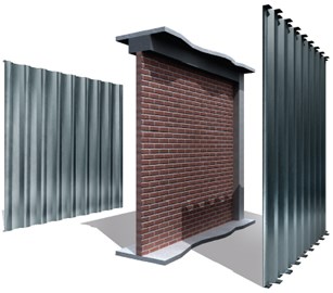
Fig. 4Installation of waved steel panels to concrete frame

a) Installation waved panel

b) Drilling of holes in wall
c) Insert of anchor

d) Application of epoxy
2.2. Design
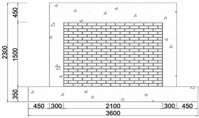
In order to evaluate improvement in seismic performance, five specimens were manufactured. As illustrated in Fig. 5, the cross-section and length of the column, upper beam, and lower beam are 300 mm×300 mm and 1,950 mm, 300 mm×450 mm and 1,700 mm, and 600 mm×350 mm and 2,700 mm, respectively. 28 days compressive strength of the concrete was 45.2 MPa. Steel reinforcements with a diameter of 13 mm were used as the longitudinal reinforcement. Stirrups and hoops with a diameter of 10 mm were also used. Cement bricks with a compressive strength of 8 MPa and absorption rate of 10 were used for the masonry, using an internal 0.5 B brick laying type. The steel material used in the wide-flange beam and waved panel was SS400 (235 MPa).
2.3. Experiments
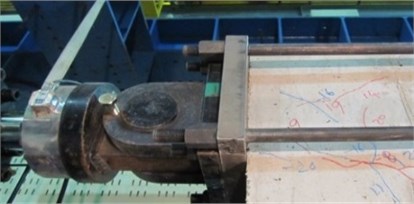
As presented in Fig. 6, the specimens were fixed to a rigid frame with high tensile bolts, through holes in the lower beam of the frame. A dynamic actuator with maximum capacity of 1,000 kN was used to apply cyclic loading at the rate of 0.5 mm/sec, using the displacement control method. The actuator and the upper beam of the specimen were fixed with bolts, employing 4 steel bars and plates for the loading. As illustrated in Fig. 7, the incremental drift allows 3 cycles for each displacement, and the plan was to apply displacement up to the drift ratio of 8 %, which is the lateral drift ratio with respect to the height of the column. Positive (+) and negative (-) displacements were repeatedly applied. The experiment was terminated when the lateral drift of the actuator was beyond 100 mm, which is its limit, or when the load of the specimen was less than or equal to 70 % of the maximum load. As Fig. 6 shows, a Linear Variable Differential Transducer (LVDT) was installed to measure the lateral drift of the specimen.
Fig. 5Details of specimens
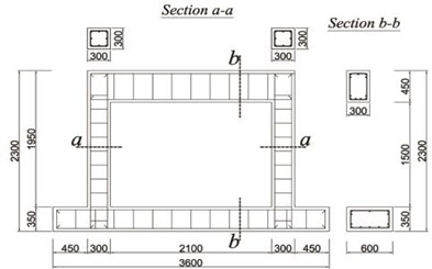
a) Reinforcement details of RC frame
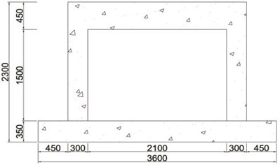
b) Bare frame
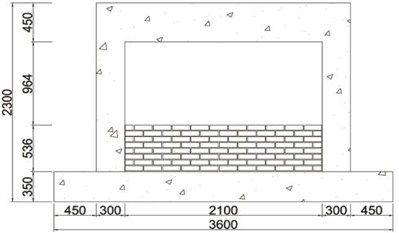
c) Masonry partially infilled frame
d) Masonry fully infilled frame
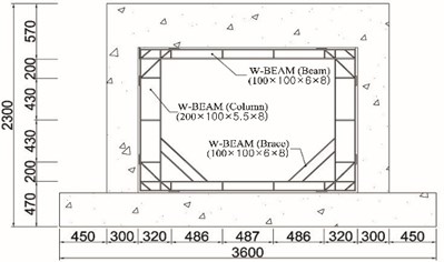
e) Retrofitted the wide-flange beam frame
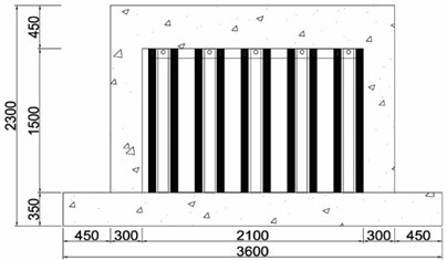
f) Retrofitted with waved steel panels
Fig. 6Test set-up
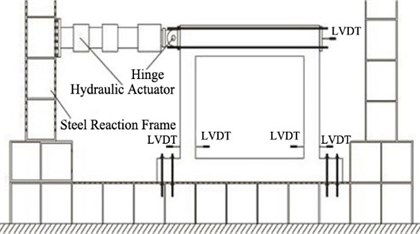
Fig. 7The incremental drift
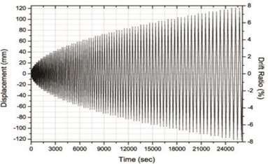
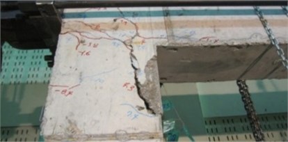
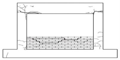
Fig. 8Crack patterns of the specimens
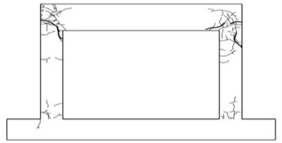
a) Bare frame
b) Failure of column in bare frame
c) Masonry partially infilled frame
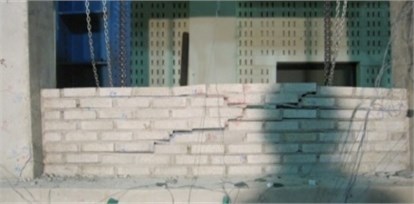
d) Failure of masonry in masonry partially infilled frame
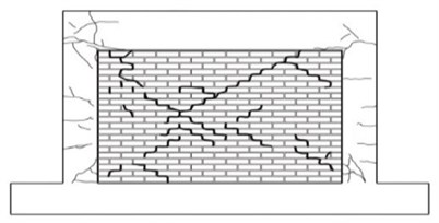
e) Masonry fully infilled frame
f) Failure of column in masonry fully infilled frame
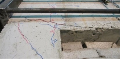
g) Retrofitted the wide-flange beam frame
h) Crack of beam in retrofitted the wide-flange frame inserted frame

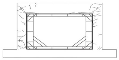
i) Retrofitted with waved steel panels
j) Failure of column in retrofitted with waved steel panels
3. Test results
3.1. Cracking and failure mode
Fig. 8 presents the cracking and failure modes of the specimens. Initial cracks developed in the lower beam-column joint at the drift ratio of 0.2 %, and additional cracks developed in the upper beam-column joints of the bare frame. Cracks also occurred at the center of the column and the crack width in the upper beam-column joint increased as the load increased. Concrete spalling was observed as the crack width increased and the experiment was terminated due to the failure of the upper beam-column joint.
For the masonry partially infilled frame, initial cracks developed in the upper beam-column joint at the drift ratio of 0.4 %. Sliding failure was observed along the masonry joint at the drift ratio of 0.7 %. Cracks occurred in the column adjacent to the masonry partially infilled wall after the failure of the masonry wall and the crack widths increased with the increasing load. The specimen of the masonry fully infilled frame revealed crack and failure modes similar to the specimen of the masonry partially infilled frame. Initial cracks occurred at the drift ratio of 0.4 %, and masonry joint sliding was observed at the drift ratio of 0.7 %. In the case of the specimen retrofitted with the wide-flange beam frame, initial cracks occurred also at the upper beam-column joint when the drift ratio of 0.6 %. As the load increased, cracks developed in the lower beam-column joints and the columns. Initial cracks developed in the upper beam-column joints of the specimen retrofitted with waved steel panels at the drift ratio of 0.7 %. There was no separation of the waved panel from the frame and large cracks or delamination did not occur. Similar to the specimen retrofitted with the wide-flange beam frame, the experiment of the specimen retrofitted with the waved panels was terminated when the load reached approximately 70 % of the maximum load after reaching its maximum load.
3.2. Load-displacement relationships
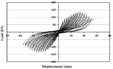
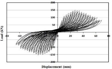
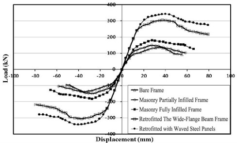
The hysteretic behaviors of the specimens under cyclic loading are presented in Fig. 9, and Fig. 10 illustrates the envelope curves of all the specimens.
From the Figs. 9 and 10, specimens retrofitted with the wide-flange beam frame and waved panels showed significantly larger maximum loads comparing with the other specimens. The specimen retrofitted with the wide-flange beam frame showed a maximum load approximately twice that of the masonry partially infilled frame specimen, and the specimen retrofitted with the waved panels showed a maximum load approximately twice that of the masonry fully infilled frame specimen.
The experimental results are summarized in Table 1. As shown in Table 1, the specimens retrofitted with partially infilled and fully infilled frames have maximum load approximately 8 % and 31 % higher, respectively, than that of the bare frame. The lateral resistance capacity of the frames increases due to the masonry wall during the initial phase of loading. However, the resistance strength decreased after cracks and failures in the masonry wall caused separation from the concrete frame.
Table 1Test results
Specimen | Maximum load [kN] | Ratio of maximum load (push) to the bare frame | |
Push | Pull | ||
Bare frame | 137.80 | –134.68 | 1.00 |
Masonry partially infilled frame | 149.04 | –146.06 | 1.08 |
Masonry fully infilled frame | 180.46 | –176.25 | 1.31 |
Retrofitted the wide-flange beam frame | 305.76 | –304.83 | 2.22 |
Retrofitted with waved steel panels | 342.66 | –340.75 | 2.49 |
Fig. 9Load-displacement curve
a) Bare frame
b) Masonry partially infilled frame
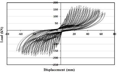
c) Masonry fully infilled frame
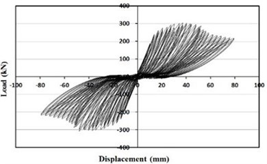
d) Retrofitted the wide-flange beam frame
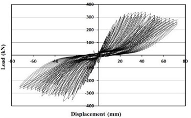
e) Retrofitted with waved steel panels
Fig. 10Envelope curve
3.3. Effective stiffness
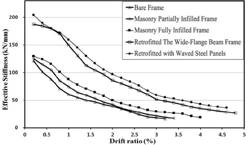
The effective stiffness of a specimen is defined as the slopes of the maximum loads to the maximum displacements under positive (push) and negative (pull) loadings as demonstrated in Fig. 11 [4]. Fig. 12 and Table 2 show the effective stiffness of each specimen. As illustrated in Fig. 9, the bare frame specimen showed a radical decrease in effective stiffness up to the drift ratio of 1 %. The reductions in effective stiffness of masonry partially infilled and fully infilled specimens were not significant until the drift ratio of 0.7 %, but a radical reduction was observed after the drift ratio of 0.7 %. The failure of the masonry wall occurred at the drift ratio of 0.7 %. Therefore, partially infilled and infilled walls do not contribute to securing stiffness after the initial loading stages. Specimens retrofitted with the wide-flange beam frame and waved panels did not exhibit a significant reduction in stiffness up to the drift ratio of 0.8 %. Although their stiffness was reduced later, the effective stiffnesses were twice larger than those of the other specimens.
Fig. 11Calculation of effective stiffness: P+: Maximum load in positive loading (push), P-: Maximum load in negative loading (pull), D+: Maximum displacement in positive loading, D-: Maximum displacement in negative loading
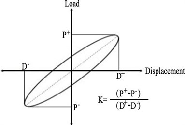
Fig. 12Effective stiffness vs. Drift ratio
3.4. Ductility
In this study, the displacement ductility can be computed by the following Eq. (1):
where is the ductility index, the ultimate displacement, is defined as the displacement corresponding to a 80 % strength degradation of the maximum strength, is defined as the displacement corresponding to the first yielding of the specimen [5].
As shown in Fig. 13 and Table 3, the specimen retrofitted with the waved panels had the highest displacement ductility. The specimen retrofitted with the wide-flange beam frame showed the second highest displacement ductility. The specimen retrofitted with the waved panels was approximately 21 % improved from the bare frame. The specimen retrofitted with the wide-flange beam frame was approximately 15 % improved from the bare frame.
Fig. 13Ductility ratio
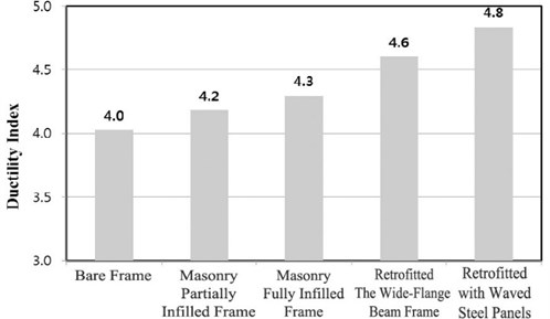
Table 2Effective stiffness of the specimen
Drift ratio (%) | Effective stiffness [kN/mm] | ||||
Bare frame | Masonry partially infilled frame | Masonry fully infilled frame | Retrofitted the wide-flange beam frame | Retrofitted with waved steel panels | |
0.2 | 121.2 | 125.1 | 129.7 | 187.4 | 204.4 |
0.6 | 88.2 | 104.9 | 115.6 | 179.5 | 180.1 |
1.0 | 60.4 | 74.3 | 87.6 | 149.3 | 159.6 |
1.4 | 50.0 | 58.9 | 70.6 | 112.5 | 130.1 |
1.8 | 42.2 | 46.2 | 57.5 | 96.5 | 105.5 |
2.2 | 34.3 | 35.5 | 44.3 | 80.2 | 90.1 |
2.6 | 24.3 | 27.9 | 36.3 | 67.6 | 76.3 |
3.0 | 18.3 | 21.8 | 29.4 | 51.3 | 59.4 |
3.4 | – | 17.4 | 26.6 | 45.2 | 52.6 |
3.8 | – | – | 21.1 | 37.6 | 46.2 |
4.2 | – | – | – | 32.7 | 40.1 |
4.6 | – | – | – | 28.4 | 36.0 |
Table 3Ductility of specimens
Specimen | Yield displacement () [mm] | Maximum displacement () [mm] | / | Ratio to bare frame |
Bare frame | 11.2 | 45.1 | 4.02 | 1.00 |
Masonry partially infilled frame | 11.5 | 48.1 | 4.18 | 1.04 |
Masonry fully infilled frame | 13.8 | 59.3 | 4.30 | 1.07 |
Retrofitted the wide-flange beam frame | 15.6 | 71.8 | 4.60 | 1.10 |
Retrofitted with waved steel panels | 16.4 | 79.3 | 4.84 | 1.17 |
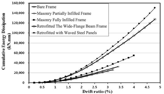
3.5. Energy dissipation
In this study, energy dissipation was evaluated by accumulating the energy dissipation of the loading cycles until 70 % of the maximum load with respect to the energy of the first cycle. As illustrated in Fig. 14, all the specimens showed similar energy dissipation up to the drift ratio of 0.7 %. However, after 0.7 %, specimens retrofitted with the waved panel and wide-flange beam frame exhibited energy dissipation larger than twice those of the other specimens.
4. Conclusions
Two retrofitting methods employing a wide-flange shaped beam frame and waved steel panels were evaluated through cyclic lateral loading tests to improve the seismic performance of existing reinforced concrete frames. The seismic performances of the retrofitted specimens were experimentally compared with the bare, masonry partially infilled, and fully infilled frames.
Fig. 14Energy dissipation of the specimen
The following specific conclusions were drawn from this study:
1) The retrofitted specimens did not exhibit any significant cracks or failures in the beam-column joints or columns. Comparisons of the maximum loads showed that the maximum loads of those two specimens were approximately twice as large as those of the other specimens. In addition, the specimens with the greatest effective stiffness, in descending order, were the specimen retrofitted with waved steel panels, wide-flange shaped beam frame, masonry fully infilled frame, partially infilled frame, and bare frame, respectively. The effective stiffness of the specimens retrofitted with waved panels and wide-flange shaped beam frame were approximately twice as large as those of the other specimens.
2) The specimens with greatest ductilities, in descending order, were the specimen retrofitted with waved panel, wide-flange shaped beam frame, masonry fully infilled frame, partially infilled frame, and bare frame, respectively. The energy dissipations of the specimens retrofitted with wave panel and wide-flange shaped beam frame were approximately twice as large as those of the other three specimens.
3) This research proposed retrofitting methods employing wide-flange shaped beam frame and waved steel panels. These methods are expected to be effective in improving seismic performance in terms of maximum load, effective stiffness, and energy dissipation.
References
-
Hashemi A., Mosalam K. M. Shake-table experiment on reinforced concrete structure containing masonry infill wall. Earthquake Engineering and Structural Dynamics, Vol. 35, Issue 14, 2006, p. 1827-1852.
-
Anil Q., Altin S. An experimental study on reinforced concrete partially infilled frames. Engineering Structures, Vol. 29, 2007, p. 449-460.
-
Altin S., Anil Q., Kara M. E., Kaya M. An experimental study on strengthening of masonry infilled RC frames using diagonal CFRP strips. Composites Part B: Engineering, Vol. 39, Issue 4, 2008, p. 680-693.
-
Tsonos A. G. Lateral load response of strengthened reinforced concrete beam-to-column joints. ACI Structural Journal, Vol. 96, Issue 1, 1999, p. 46-56.
-
Sheikh S. A., Khoury S. S. A performance-based approach for the design of confining in tied columns. ACI Structural Journal, Vol. 49, Issue 4, 1997, p. 421-431.
About this article

This work was supported by the National Research Foundation of Korea(NRF) Grant funded by the Korea Government (MSIP) (NRF-2013R1A2A2A01067754).
