Abstract
Although numerous structural identification methods have been proposed, most of them are problem dependent, rely on classical approaches based on mathematical concepts, and/or are based on changes in modal characteristics that are not sensitive to damage. This study aims to utilize a metaheuristic modified optimization algorithm for the identification of damage in a numerically modeled 5-MW reference turbine. A variety of damage severities, sensor numbers and noise percentages were investigated. The results show that the presented algorithm’s identification accuracy is not affected by the magnitude of damage whereas sensor configuration and noise severity do have a significant effect. The satisfying results encourage considering its application on in-situ structural identification tasks based on experimental measurements.
1. Introduction
Despite the fact that numerous methods for structural identification have been proposed and developed, most of these rely on classical approaches based on sound mathematical theories, which have limitations in one way or another [1]: some require gradient information to guide their search in a point-to-point basis, which also relies on a relatively good initial guess, something that becomes unpractical as the complexity of the problem increases, other require special conditions to be applied in identification problems, such as assuming a certain noise or excitation pattern, assuming that all components of vibration response (acceleration, velocity and displacements) are measured and/or that an extensive array of sensors is implemented. In their best performance, they still obtain near optimal, i.e. close to real values, structural parameters [1].
Numerous new and promising metaheuristic algorithms were proposed recently and were successfully applied on a variety of problems, namely: economy, production, resource allocation, management, design optimization and even more. In the field of structural identification, however, their application was limited to identification problems of simple structures such as beams [2] and frames [3] when compared to classical approaches, thus motivating the research community to tap into their potential in complex structural identification problems.
Wind turbines have gained an increasing attention over the years motivated by the increasing numbers of such turbines and their various installation locations and foundation types, the continuously increasing size and production capabilities of such turbines as well as the fact that such structures are subjected to fluctuating wind loads, making them prone to damage.
The inspection of such wind turbines can prove to be costly and is not always possible due to a variety of constraints such as weather conditions. Thus, wind turbine manufacturers, owners and operators could benefit from a remote structural identification system that alerts the investigation teams in case of damage and provides them with the vicinity of damage.
Structural identification is the process of determining the dynamic structural parameters, namely: mass, stiffness and damping of a structure utilizing vibration-based measurements, in order to identify the current state of a structure and detect damage. Due to the complexity of wind turbines, the structural identification is limited to the identification of stiffness only. In this context, the structural identification problems are treated as optimization problems with the objective to minimize errors between measured and predicted data.
Damage, in general, is a change introduced to any structural characteristic that adversely affects the current or future performance of the structure [4]. In the context of this contribution, it is considered the decrease in the structural stiffness of the supporting structure.
When identifying damage, four levels exist based on the information they provide about the structural damage [5]. These are as follows: Level I – Detection, Level II – Location, Level III – Quantification and Level IV – Prediction of remaining service life.
A general review of structural identification methods and their application is documented in [6, 1, 7]. Furthermore, a review to damage detection techniques in wind turbines as a part of the implemented structural health monitoring system is provided in [8], with special emphasis on blades and towers. Another review to condition monitoring and fault detection of wind turbines is presented in [9].
Being considered amongst the most common damage detection methods, vibration-based approaches rely on the measurement of the vibration response of structures from excitations and the extraction of structural features from those to determine structural parameters, and ultimately, structural damage.
Structural identification and damage detection of rotor blades subjected to hammer input forces and natural wind excitation was studied in [10]. Damage was identified from modal characteristics induced by loosening the bolts at the root of one blade. Although three different damage techniques were used, the results were inconclusive. This was attributed to the noise pollution of the signals, manual triggering process and inadequate sensor placement.
Piezoceramic actuators were used in [11] in the structural identification of blades. Four different methods were used, which clearly indicated the presence of damage, but failed sometimes in predicting the location of damage.
The components of an automated structural identification system for wind turbines based on smart wireless sensors was studied in [12]. The system was applied on two wind turbines to obtain the numerical model from measurement data.
The structural health monitoring was presented as a process in statistical pattern recognition in [13]. The modal assurance criterion was used in the analysis of changes in modal deflections. The study shows that a change of 4 % in natural frequency corresponds to 25 % change in stiffness in one of the blades.
Damage detection, in the form of foundation scour, was studied in [14] using a frequency domain decomposition technique. Vibration response was recorded at tower top and bottom flange, and natural frequencies and mode shapes were used in damage detection.
Coupling both local and global structural health monitoring for offshore wind turbines was presented in [15]. The considered structure is a laboratory model of a tripile offshore wind turbine supporting structure and vibration was induced by releasing the structure from an initial displaced state. However, some instrumentation, especially those for local identification, were placed close to the damage location.
The use of optimization algorithms in structural identification and damage detection for simple structures such as beams, frames and plates is already studied, yet the complex problem of structural identification of wind turbines using such optimization algorithms is not yet established. Furthermore, structural identification using classical approaches is sometimes inconclusive and does not consider noise. Another issue arises when relying on the change of modal characteristics to detect damage, as such change is sometimes insensitive to damage [16]. Classical methods, at their best performance, still are less effective than non-classical methods based on optimization algorithms [1], thus motivating the development of a vibration-based structural identification method utilizing optimization algorithms.
This study aims to utilize a modified adaptive harmony search algorithm to perform the vibration-based structural identification and damage detection of the supporting structure of numerically modeled offshore wind energy conversion devices to achieve a Level III detection accuracy. A variety of damage severities, sensor numbers and noise percentages were investigated to detect damage, which is considered as a reduction in the fore-after stiffness of the turbine’s supporting structure.
2. The dynamic analysis of wind turbines
The numerical identification and damage detection scheme based on optimization algorithms requires the calculation of the vibration response of the considered structure to work.
As a matter of fact, the presented identification scheme can be applied to any structure, provided that an accurate structural analysis routine is “plugged-into” the algorithm. Nevertheless, this contribution investigates the application of the identification method on offshore wind turbines.
The vibration analysis of wind turbines is a complex task that involves the calculation of the aerodynamic response of blades, the operational status of the wind turbine and the hydrodynamic analysis of currents and waves.
In order to approximate the vibration response of the structural components of the wind turbine, an open source program called Fatigue, Aerodynamics, Structures and Turbulence (FAST) is used. The accuracy and adequacy of FAST was tested in [17] and [18].
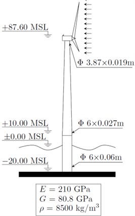
For the considered identification problem, a benchmark 5-MW offshore wind turbine developed by NREL [19] is used. The geometry and structural characteristics of the Rotor Nacelle Assembly (RNA) and blades as well as the control systems of the considered turbine are taken “as is” from [19]. For the turbine tower and monopile supporting structure, the values used in the OC3 final report [17] are adopted. The structural characteristics of the turbine supporting structure define a monopile of 30 m height (+10 m above the Mean Sea Level (MSL)) having an outer diameter of 6m and a wall thickness of 0.06m followed by a tower of 77.6 m height having a tapering cross section which starts at +10 m MSL with a diameter of 6 m and wall thickness of 0.027 m, and ends at +87.6 m MSL with a diameter of 3.87 m and wall thickness of 0.019 m. The turbine tower, as detailed in Fig. 1, is modeled in FAST using 16 input stations which define its structural properties.
Fig. 1A schematic diagram of the considered wind turbine
It is assumed that the turbine blades are facing wind directly, thus fore-after vibrations are dominant. A turbulent inflow wind was generated using an open source software called TurbSim, also provided by NREL. The generated inflow wind has a characteristic wind speed of 10 m/s. To limit the influence of RNA dynamics, the turbine was set to idling, i.e. its RPM = 0.
3. Formulating the optimization problem
Structural identification and damage detection can be treated as an optimization problem with the objective to minimize errors between the predicted response from a trial solution vector and the measured/real response obtained from the structure being measured or numerically modeled.
Mathematically, it is required to find that minimizes where and:
where is the total length of the time history and is the number of acceleration measurement locations.
To simplify the problem, it is assumed that the turbine is idling and faces wind directly. Thus, the fore-after vibrations are dominant. Furthermore, only stiffness terms are to be identified, thus, the structure could be represented by a solution vector containing fore-after stiffness related data of each input station, thus:
The stiffness terms in Eq. (2) are selected from a predefined “Search Space” which is defined by assuming the upper bounds, lower bounds and step sizes of each element in the solution vector as follows:
In this study, the upper bound , lower bound and step size are taken to be 100 %, 50 % and 1% of the fore-after stiffness values defined in [17], creating a search space of 2.0947×1027 possible solution vectors.
4. The Modified Adaptive HaRmony SearcH ALgorithm (MARSHAL)
Despite being amongst the most powerful optimization algorithms developed so far, Harmony Search (HS) algorithms still require some improvements to tackle the complex problem of structural identification. HS is a recently developed metaheuristic algorithm presented in [20], which emerged as a powerful and promising optimization algorithm. HS is more efficient, faster and easier in implementation than other well-known metaheuristic algorithms such as the Genetic Algorithms (GAs) [21]. Recent optimization studies such as [22] and [23] show that HS is a superior optimization algorithm with promising potential. The gradient-free nature of the HS algorithm enabled it to achieve satisfying results even for the most complex optimization problems, such as structural identification and damage detection [2]. Classical methods, on the other hand, get trapped in local optima due to the complexity of the considered optimization problem.
The adopted optimization algorithm was presented in [3], and is a modification of the basic harmony search algorithm. The basic HS is presented first, followed by the modifications that were applied to it to develop MARSHAL.
The basic HS consists of four steps, namely: (1) – Initialization, (2) – Improvising a new harmony, (3) – Updating and (4) – Termination. Collectively, steps (2) to (4) could be referred to as “Iterative Search”.
4.1. Initialization
During this phase, the control parameters of the HS are initialized. These control parameters are:
• The Harmony Memory Size (), which corresponds to the number of solutions within the harmony memory ().
• The Harmony Memory Considering Rate (), which controls global search.
• The Pitch Adjusting Rate (), which controls local search.
• The termination criteria, e.g. the maximum number of iterations.
Once the control parameters are initialized, the Harmony Memory gets filled with randomly assumed solution vectors as in Eq. (2) and their corresponding objective function calculated as per Eq. (1), thus:
4.2. Improvising a new harmony
For each iteration, a new trial solution is assumed using an element by element approach. For each element , there is a probability that it is assumed from within the , i.e.:
where is a randomly assumed number between 0 and 1.
Furthermore, there is a probability for a selected element from within the to be shifted slightly, i.e.:
where and are two independent random variables between 0 and 1, is the bandwidth, taken to be 4 in this study.
4.3. Updating
Once all elements of the solution vector are defined, the objective function is calculated. For a minimization problem, the worst solution corresponding to the solution with the highest objective function, is determined and substituted by if .
4.4. Termination
The HS terminates if a predetermined maximum number of iterations is reached, or when the objective function drops to zero.
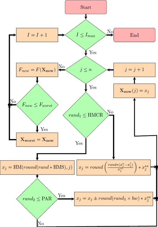
The flowchart of the basic HS algorithm is shown in Fig. 2 and 3.
Fig. 2Flowchart of basic HS initialization
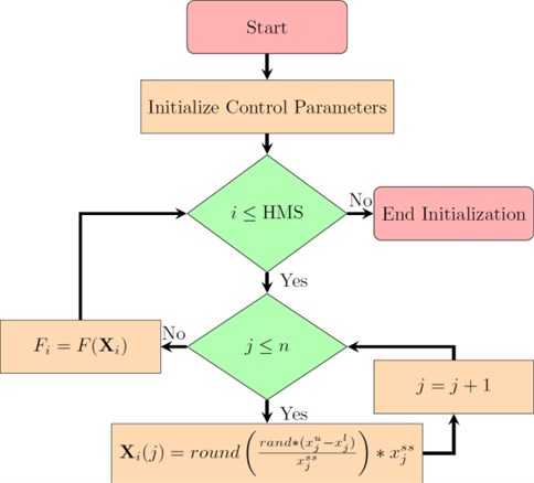
Fig. 3Flowchart of basic HS iterative search
4.5. Modifications to the basic harmony search algorithm
Metaheuristic algorithms could be improved by modifying its control parameter structure and/or by hybridizing it with other algorithms. MARSHAL was derived from the basic harmony search by applying following improvements:
1) An experience-based control parameter selection system developed in [24].
2) The addition of a local effect, developed in [3].
3) A two-level experience-based search space reduction method developed in [3].
One of the main drawbacks of metaheuristic algorithms is the requirement of parameter fine-tuning which are, usually, problem dependent, thus leading to the development of the Adaptive Harmony Search (AHS) algorithm in [24]. In the AHS, the control parameters and are adaptively selected during each iteration as follows:
where and are the AHS control parameters for iteration , is the exponential function, is a normally distributed random number, is the learning rate, recommended to be and and are the average values of the control parameters for every solution vector in .
Thus, the initialization of such modified algorithm requires the initialization of the and for each solution vector within the as well. Thus leading to an expanded storage of solutions as follows:
Another issue arises from the fact that the stiffness terms are coupled, and require sometimes a simultaneous change to improve a current solution. Thus, the so-called “local effect” was introduced in [3], which controls the changes in neighboring stiffness entries if a certain stiffness entry has been edited by pitch adjustment. Mathematically speaking, assuming that an element has undergone pitch adjustment then:
where and are the neighboring elements of in the solution vector . The is the Local Effect Rate, calculated adaptively similar to and , thus:
Thus, the expands once more to store the values of , thus:
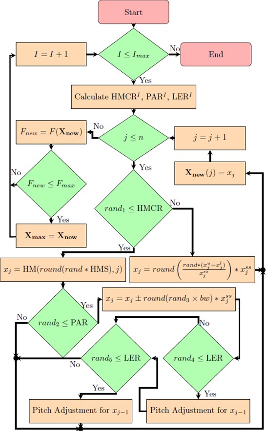
A flowchart of the resulting iterative search is presented in Fig. 4.
Fig. 4Flowchart of modified adaptive HS iterative search
Another drawback metaheuristic optimization algorithms have, is the fact that their performance is inversely proportional with the size of the search space. Thus, for an algorithm to solve problems of large search spaces, an experience-based dynamic reduction of the search space has to be carried out utilizing the experience gathered so far from the optimization process.
Most of the metaheuristic optimization algorithms have some sort of “storage system” that stores a chosen population of good solutions to assist in the assumption of new solutions during the iterative search. In HS based algorithms, it is the Harmony Memory. This particular storage system also contains the “experience” of the algorithm, which smart search space reduction schemes should utilize in highlighting potential regions of the search space, in order to increase the efficiency of the optimization algorithm.
Thus, a modified search space reduction scheme was suggested in [3] based on the search space reduction developed in [1]. Originally, an optimization run is divided into number of sub-runs. Once a predetermined number of sub-runs have passed, the corresponding number of optimum solutions is obtained and stored in a storage matrix:
These solutions are used to redefine the upper bound and lower bound as follows:
where and are the mean and standard deviation of the i-th column in , and are the initial upper and lower bounds, respectively, and is a predetermined window.
To further utilize the experience gained in the solutions stored in , another level of reduction is implemented [3]. The second level reduces the search space during a sub-run, i.e. an iteration level search space reduction scheme in addition to the original sub-run level reduction scheme. Hence, after a predetermined number of iterations have passed, the search space is reduced using equations similar to Eqs. (15) and (16), but now being applied on the solutions stored in the .
Another modification is implemented to the original search space reduction scheme to prohibit the search space from getting too small or even collapsing. This is done by defining a minimum search space size. Thus, once the search space reduction scheme is used, the following check is implemented:
where is the minimum window to be kept between the upper and lower bounds.
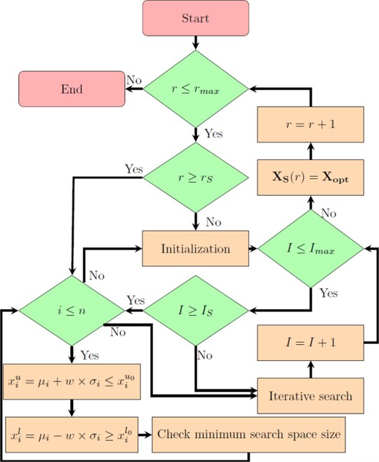
Implementing these modifications resulted in the development of MARSHAL, which is a self-learning, experience-based, adaptive optimization algorithm capable of coping with the variation of the optimization problem’s size via its built-in improved search space reduction scheme. MARSHAL’s flowchart is shown in Fig. 5
5. Identification cases and settings
A variety of identification and damage detection cases, summarized in Table 1, were considered to study the effect of damage magnitude, number of sensors and location, and noise percentage on the accuracy of identification. In all cases, damage is applied to the 6th input station of the supporting structure in the form of a reduction in the fore-after stiffness. This input station corresponds to the location that is just above the transition piece, which connects the monopile with the turbine tower. The tower is grouted to such transition piece, creating a potential location for damage propagation. The sensors are applied at locations above the MSL for practical considerations.
Table 1Structural identification cases
Number of sensors () | Sensor location | Noise (%) | (%) |
10 | Station No. 4, 5, 6, 7, 8, 9, 11, 13, 14, 16 | 0 | 10 |
6 | Station No. 5, 6, 8, 10, 12, 16 | 2 | 5 |
1 | Station No. 16 | 5 | 3 |
10 | 0 |
Fig. 5Flowchart of MARSHAL
The magnitude of damage can be represented by a Damage Index (DI), defined as follows:
where:
where and are the undamaged and damaged stiffness value of the th input station.
The performance of MARSHAL is first tested for different damage magnitudes while using a constant number of 10 sensors and a 0 % noise value. The results, as detailed later on, show that MARSHAL is unaffected by the damage magnitude, i.e. has approximately the same identification accuracy regardless of the damage magnitude. Thus, the performance of MARSHAL is then tested using variety of sensor and noise scenarios while keeping the damage magnitude at a constant 10 %.
For each identification case, 10 optimization runs were performed, having a total of 16,000 iterations, and subdivided into 8 sub-runs of 2,000 iterations each. Once all runs are performed, the results are stored and averaged. Finally, the damage index for each input station is calculated according to Eq. (19).
A time history of 2 seconds discretized into 0.01 second increments is used for noise free signals, and is increased to 10 seconds with a finer discretization of 0.001 seconds when identifying damage using noisy signals.
MARSHAL’s settings were: initial 0.50, initial 0.35 and initial 0.30, 10 and 0.35. The sub-run level SSRM starts at the 4th run, whereas the iteration level SSRM starts after 5 % of the iterations per sub-run.
6. Results of identification
As the algorithm progresses, the average of the structures stored within the as well as the best structure, corresponding to the lowest objective function, converge to the real/correct structure. This is shown in Figs. 5, 6 and 7, for three different stages, namely: early stage (shortly after beginning the sub-run), middle stage (at around 50 % of iterations) and final stage (near end of sub-run), respectively.
To assess the effect of damage magnitude on the accuracy of the algorithm, a variety of damage values for station No. 6 were tested, namely: 10 %, 5 %, 3 % and 0 %. Here, the number of sensors was set to 10 and no noise was considered. Results obtained from these setups are detailed in Table 2.
Table 2Identification results: damage magnitude effect
(%) | (%) | |||||||||||||||
1 | 2 | 3 | 4 | 5 | 6 | 7 | 8 | 9 | 10 | 11 | 12 | 13 | 14 | 15 | 16 | |
10 | 0 | 0 | 0 | 0 | 0 | 10.1 | 0 | 0 | 0 | 0 | 0 | 0 | 0 | 0 | 0 | 0 |
5 | 0 | 0 | 0 | 0 | 0 | 5 | 0 | 0 | 0 | 0 | 0 | 0 | 0 | 0 | 0 | 0 |
3 | 0 | 0 | 0 | 0 | 0 | 3 | 0 | 0 | 0 | 0 | 0 | 0 | 0 | 0 | 0 | 0 |
0 | 0 | 0 | 0 | 0 | 0.1 | 0 | 0 | 0.1 | 0 | 0 | 0 | 0 | 0 | 0 | 0 | 0 |
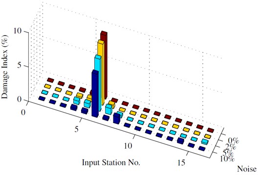
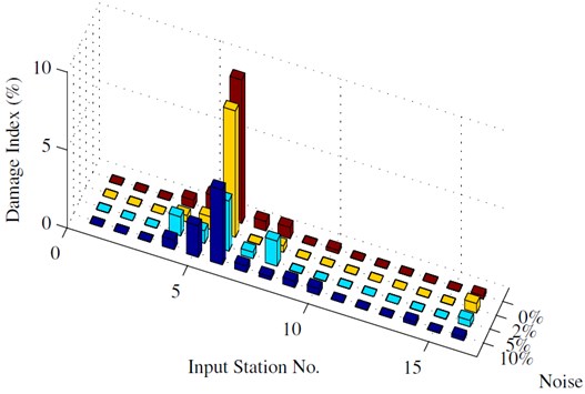
Furthermore, the influence of various sensor scenarios is considered for a variety of noise percentages. These results are detailed in Table 3 and further summarized in Figs. 8, 9 and 10.
Based on the results in Tables 2 and 3, following conclusions could be drawn:
• The results obtained for various damage magnitudes show that MARSHAL’s identification and detection capabilities are unaffected by the severity of damage.
• In the case of damage detection, limited instrumentation could compromise the accuracy of detection at high noise values. For example, only the existence and location of damage could be concluded from the results obtained using a single sensor at the top of the tower under 10 % noise, thus achieving only a Level II damage detection.
• As the number of sensors increase, better detection levels are achieved, as the existence, location and severity of damage can be concluded from these results, achieving a Level III detection.
• Despite being a challenging problem, satisfying results were obtained even at high noise values, except for the 1-sensor scenario.
• The practical problem that arises is the fact that most wind turbines have a limited number of sensors installed near the rotor-nacelle assembly (around the top of the tower). To improve the results obtained for such limited instrumentation, it becomes necessary to include a data filtering subroutine before passing the measured vibration data to MARSHAL. It is noteworthy that no filtering subroutine was used in any of the numerical study cases, as it was sought to test MARSHAL’s limits whilst exposing it to the full noise magnitude.
Fig. 6Early stage of identification sub-run
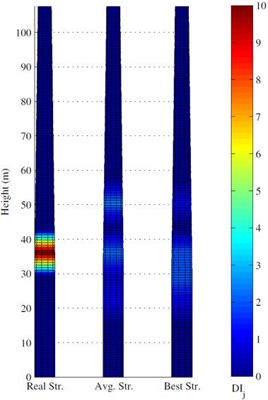
Fig. 7Middle stage of identification sub-run
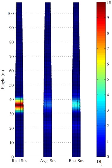
Fig. 8Final stage of identification sub-run
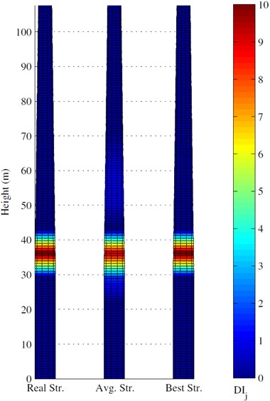
Table 3Identification results: sensor and noise effect
Noise (%) | (%) | ||||||||||||||||
1 | 2 | 3 | 4 | 5 | 6 | 7 | 8 | 9 | 10 | 11 | 12 | 13 | 14 | 15 | 16 | ||
10 | 0 | 0 | 0 | 0 | 0 | 0 | 10 | 0 | 0 | 0 | 0 | 0 | 0 | 0 | 0 | 0 | 0 |
2 | 0 | 0 | 0 | 0 | 0.1 | 9.6 | 0.1 | 0 | 0 | 0 | 0 | 0 | 0 | 0 | 0 | 0 | |
5 | 0 | 0 | 0 | 0.2 | 0.4 | 8.8 | 0.4 | 0 | 0 | 0 | 0 | 0 | 0 | 0 | 0 | 0 | |
10 | 0 | 0 | 0 | 0.1 | 0.1 | 8.7 | 0.3 | 0.9 | 0.1 | 0 | 0 | 0 | 0 | 0.1 | 0 | 0 | |
6 | 0 | 0 | 0 | 0 | 0.1 | 0.2 | 9.3 | 0 | 0 | 0 | 0 | 0 | 0 | 0 | 0 | 0 | 0 |
2 | 0 | 0 | 0 | 0.2 | 0.4 | 8.9 | 0.5 | 0 | 0 | 0 | 0 | 0 | 0 | 0 | 0 | 0 | |
5 | 0 | 0 | 0 | 0.5 | 0.6 | 7.6 | 0.9 | 0.3 | 0 | 0 | 0 | 0 | 0 | 0 | 0 | 0.2 | |
10 | 0 | 0 | 0 | 0.3 | 0.3 | 6.3 | 0.2 | 1.0 | 0 | 0 | 0 | 0 | 0 | 0.3 | 0 | 0 | |
1 | 0 | 0 | 0 | 0 | 0.5 | 1.2 | 9.2 | 0.6 | 0.7 | 0 | 0.2 | 0 | 0 | 0 | 0 | 0 | 0.2 |
2 | 0 | 0 | 0 | 0.4 | 0.8 | 8.1 | 0 | 0.4 | 0 | 0 | 0 | 0 | 0 | 0 | 0 | 0.6 | |
5 | 0 | 0 | 0 | 1.2 | 0.8 | 3.2 | 0.4 | 1.6 | 0 | 0 | 0 | 0 | 0 | 0 | 0 | 0.4 | |
10 | 0 | 0 | 0 | 0.6 | 2.0 | 4.8 | 0.4 | 0.2 | 0.4 | 0.4 | 0 | 0 | 0 | 0.2 | 0 | 0.2 | |
Fig. 9Identification results: 10 sensors
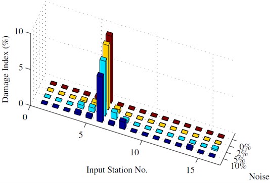
Fig. 10Identification results: 6 sensors
7. Conclusions
This study aims to utilize a modified adaptive harmony search algorithm to perform the vibration-based structural identification and damage detection of numerically modeled offshore wind energy conversion devices to achieve a Level III detection accuracy. A variety of damage severities, sensor numbers and noise percentages were investigated to detect damage, which is considered as a reduction in the fore-after stiffness of the turbine’s supporting structure.
Fig. 11Identification results: 1 sensor
In this contribution, a Modified Adaptive HaRmony SearcH ALgorithm (MARSHAL) was presented and utilized in the structural identification and damage detection of offshore wind turbines. The vibration response required for the use of MARSHAL was obtained via an open source program called FAST (Fatigue, Aerodynamics, Structures and Turbulence), which was developed and validated by the National Renewable Energy Laboratory (NREL).
MARSHAL was applied on a benchmark 5-MW offshore wind turbine developed by NREL, and considered a variety of structural identification and damage detection problems that investigate the effect of damage magnitude, sensor number and location and noise percentage on the accuracy of identification.
The identification accuracy of MARSHAL was unaffected by the magnitude of damage, but depended – logically – on the number of sensors and the noise percentages involved in the identification run.
Outstanding results were obtained when 10 sensors were used, not only detecting the presence of damage, but locating and quantifying it as well, achieving the desired Level III detection accuracy. On the other hand, however, the results involving a single sensor could only detect the presence and the location of damage at extreme 10 % noise values and failed to obtain a good approximation of the damage magnitude, thus achieving a Level II identification accuracy.
A practical problem arises from the fact that most wind turbines have only a single accelerometer installed at the tower top. Thus, it is necessary to include a data filtering subroutine before passing the vibration response to MARSHAL, in order to decrease the effective noise percentage and improve the identification accuracy, since the 1-sensor scenario achieves a Level III detection at lower noise percentages.
References
-
Koh C. G., Perry M. J. Structural Identification and Damage Detection using Genetic Algorithms. CRC Press, London, UK, 2010.
-
Miguel L. F. F., Miguel L. F. F., Kaminski Jr J., Riera J. D. Damage detection under ambient vibration by harmony search algorithm. Expert Systems with Applications, Vol. 39, 2012, p. 9704-9714.
-
Jahjouh M. M., Nackenhorst U. Structural identification of two dimensional shear buildings using a modified adaptive harmony search algorithm. Engineering Optimization, CRC Press, London, UK, Vol. 4, 2014, p. 193-198.
-
Sohn H., Farrar C., Hemez F. A Review of Structural Health Monitoring Literature: 1996-2001. Technical Report, Los Alamos National Laboratory (LANL), Los Alamos, NM, 2004.
-
Rytter A. Vibrational Based Inspection of Civil Engineering Structures. Ph.D. Thesis, Aalborg, 1993.
-
Doebling S., Farrar C., Prime M., Shevitz D. Damage Identification and Health Monitoring of Structural and Mechanical Systems from Changes in Their Vibration Characteristics: A Literature Review. Report LA-13070-MS, Los Alamos National Laboratory, Los Alamos, NM, 1996.
-
Sirca G., Adeli H. System Identification in structural engineering. Scientica Iranica, Vol. 19, Issue 6, 2012, p. 1355-1363.
-
Ciang C., Lee J.-R., Bang H.-J. Structural health monitoring for a wind turbine system: a review of damage detection methods. Measurement Science and Technology, Vol. 19, Issue 12, 2008, p. 122001.
-
Hameed Z., Hong Y., Cho Y., Ahn S., Song C. Condition monitoring and fault detection of wind turbines and related algorithms: a review. Renewable and Sustainable Energy Reviews, Vol. 13, Issue 1, 2009, p. 1-39.
-
Gross E., Zadoks R., Simmermacher T., Rumsey M. Application of damage detection techniques using wind turbine modal data. Proceedings of the 37th Aerospace Sciences Meeting and Exhibit, American Institute of Aeronautics and Astronautics, Reston, 1999, p. 1-6.
-
Ghoshal A., Sundaresan M. J., Schulz M. J., Frank Pai P. Structural health monitoring techniques for wind turbine blades. Journal of Wind Engineering and Industrial Aerodynamics, Vol. 85, 2000, p. 309-324.
-
Rolfes R., Zerbst S., Haake G., Reetz J., Lynch J. P. Integral SHM-system for offshore wind turbines using smart wireless sensors. Proceedings of the 6th International Workshop on Structural Health Monitoring, Stanford, USA, 2007, p. 1-8.
-
Adams D., White J., Rumsey M., Farrar C. Structural health monitoring of wind turbines: method and application to a HAWT. Wind Energy, Vol. 14, 2011, p. 603-623.
-
Gomez H. C., Gur T., Dolan D. Structural condition assessment of offshore wind turbine monopole foundation using vibration monitoring data. SPIE Smart Structures and Materials + Nondestructive Evaluation and Health Monitoring, Vol. 8694, 2013.
-
Schröder K., Scholle N., Rolfes R., Lohaus L. An Approach for local-global structural health monitoring for offshore wind energy converters. Proceedings of the International Wind Engineering Conference, Hannover, Germany, 2014, p. 318-325.
-
Farrar C., Doebling S. Lessons learned from applications of vibration based damage identification methods to large bridge structure. Proceedings of the International Workshop on Structural Health Monitoring, Vol. 836, 1997, p. 351-370.
-
Jonkman J., Musial W. Offshore Code Comparison Collaboration (OC3) for IEA Task 23 Offshore Wind Technology and Deployment. Technical Report December, National Renewable Energy Laboratory (NREL), 2010.
-
Jonkman J., et al. Offshore Code Comparison Collaboration Continuation (OC4), Phase I Results of Coupled Simulations of an Offshore Wind Turbine with Jacket Support Structure. Technical Report March, National Renewable Energy Laboratory (NREL), 2012.
-
Jonkman J., Butterfield S., Musial W., Scott G. Definition of a 5-MW Reference Wind Turbine for Offshore System Development. Technical Report February, Los Alamos National Laboratory (LANL), Los Alamos, NM, 2009.
-
Geem Z., Kim J., Loganathan G. A new heuristic optimization algorithm: harmony search. Simulation, Vol. 76, 2001, p. 60-68.
-
Yang X. Nature-Inspired Metaheuristic Algorithms (1st Ed.). Luniver Press, United Kingdom, 2008.
-
Degertekin S. O. Harmony search algorithm for optimum design of steel frame structures: A comparative study with other optimization methods. Structural Engineering and Mechanics, Vol. 29, 2008, p. 391-410.
-
Degertekin S. O., Hayalioglu M. S., Gorgun H. Optimum design of geometrically non-linear steel frames with semi-rigid connections using a harmony search algorithm. Steel and Composite Structures, Vol. 9, 2009, p. 535-555.
-
Hasancebi O., Erdal F., Saka M. An adaptive harmony search method for structural optimization. Journal of Structural Engineering, Vol. 136, 2010, p. 419-431.
About this article

