Abstract
Hazardous effects of blasting the boulder with the new breaking-blasting equipment-tandem shaped charging warhead are mainly air shock wave, seismic wave and blast slung shot. Blast-induced ground vibration is one of the inevitable effects and may cause substantial damage to nearby structures. Started from the formation process and mechanism of ground vibration to study the seismic wave, the research attained curve of vibration velocity of monitoring points by TC-4850 and carried out differential and fast Fourier transform analysis of the curve. And the results concluded that blasting vibration with tandem shaped charging warhead mainly comes from prime charge; the attenuation law can be predicted by Sadev’s Formula. Explosion vibration frequency range is 20-150 Hz, while with the increase of distance from the blasting center, blasting vibration intensity attenuates rapidly, vibration duration increases and vibration frequency gradually reduces. Compared with general rock blasting, its attenuation rate of blasting vibration is faster with higher frequency and smaller impact on buildings, but the harm effects should not be ignored for the special application environment.
1. Introduction
To overcome war-time enemies’ obstacles of artificial and natural rock or concrete as well as barrier-breaking problem of the boulder caused by geological disasters, Xu Haoming and Gu Wenbin proposed a barrier-breaking scheme with breaking-blasting tandem blasting [1]. The charging structure proposed in their scheme is more conducive for exploiting explosive energy, which can smash the boulder once and greatly reduce the time for emergency rescue or blasting obstacles [2].
Damaging effects of blasting the boulder with tandem shaped charging warhead (TSCW) include blasting shock waves, blasting flying rocks and blasting vibration. Explosive exploded in the air, the harmful effects of air shock wave maximum in blasting near the field. With the increase of the distance, air shock wave intensity decays rapidly, the harmful effects of also greatly reduced [3, 4]. The seismic wave generated by the explosion is different from that of the shock wave, and its attenuation is slow, and the influence area is much larger than that of the shock wave.
There are just a few studies on seismic waves caused by blasting with shaped charging. Gordon F. Rever and P. E. present practical methods regarding blast design and risk management practice that have been used successful at high-exposure projects located in or Boston and other cities in the USA [5]. Ronald Pape, Kim R. Mniszewski and Anatol Longinow have studied that explosion phenomena and effects of explosions on structures [6]. Analysis of the ground vibrations produced by surface and near-surface explosions, Donald G. Albert carried that in most situations harm effects from blast overpressure will occur long before damaging levels of ground vibration are reached, so it is likely that civilian perceptions of vibration are produced by coupling from the air blast [7]. Different from ordinary rock blasting or explosion in air, its total charge is small, prime charge explodes in the air while the post bullet explodes after entering the isolated blasting barriers which shares relatively small contact area with the rock ground. Consequently, it’s blasting vibration is much smaller than that of the large-scale explosion in general rock medium, thus, its harm effects of blasting vibration are often overlooked. However, environment and condition of blasting barriers are relatively complicated, especially in geological disaster areas, barriers are usually located near the damaged buildings; therefore, even with vibrations are smaller than damaging limitations, those cracks in buildings may extend.
Hence, when blasted by tandem shaped charging; explosion vibrations may cause secondary damage to the building. Besides, more rocks exist in the geological medium where the boulder locates, amplitude of its seismic wave may be higher than that of the general soil medium, so blasting vibration effects of TSCW blasting should be taken seriously. Several trials indicated that the ground tremors obviously for blasting vibration, and stones slip down in the nearby districts. To evaluate vibration damaging effects of the TSCW system on breaking and blasting boulder, it is imperative to study the blasting vibration of the shaped charging explosion.
By setting measuring points of blasting vibration in the explosion area, the ground vibration of tandem shaped charging explosion was monitored. With analysis on the ground vibration signals from such perspectives as blasting vibration velocity (BVV), vibration duration (VD) and vibration frequency (VF), the law of blasting vibration with TSCW has been attained, which can provide further reference for controlling and protecting damaging effects.
2. Formation process and mechanism of seismic wave with TSCW barrier breaking
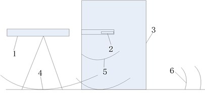
The action mechanism of TSCW is that the shaped charging jet produced by the explosion of prime shaped charging acts on the rock and forms holes, then blasting bullets enter the rock and blast; the boulder smashes and generates transportable small pieces of rock. When blasting the boulder with shaped charging, the explosion belongs to the non-contact explosion on the ground, and its blasting seismic wave mainly comes from two parts (as is shown in Fig. 1): on one hand, shaped charging structure explodes in the air and generates shock wave which acts on the ground [8], forms the motivation to the ground and transmits in the form of seismic wave to the far region; on the other hand, detonation and the air shock wave produced by explosion of shaped charging act on barrier-breaking target, meanwhile, following bullet explodes in barrier-breaking targets and produces motivation. As there exists contact between the target and ground, the above energy transmits to be around through elastic wave inside the target and forms the seismic wave.
Fig. 1Schematic diagram on formation of seismic waves of blasting boulder with TSCW: 1 – shaped charging, 2 – rear bullet, 3 – boulder, 4 – air shock wave and detonation product, 5 – elastic wave transmitting inside the barrier-breaking target, 6 – seismic wave
Explosion of shaped charging in the air may destruct and damage to different extents. When its distance from blasting center is smaller than 10-15 times of charging radius, the target is influenced by explosion products and shock wave at the same time, but when the distance is larger than it, the target is only influenced by the air shock wave [9]. In the test, height of prime charge from the ground is greater than 15 times of charging radius, so the ground is just influenced by the air shock wave instead of detonation products. with the increase of distance from blasting center.
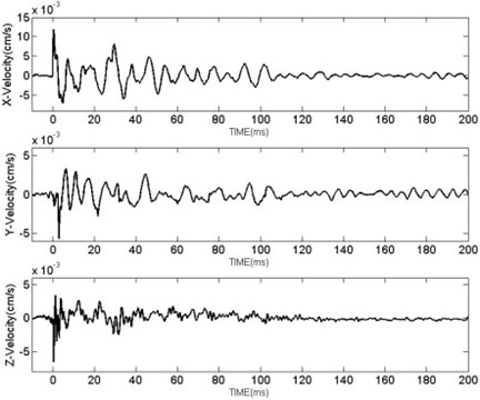
When it is near the explosion center, it is difficult to specify separation distance between detonation products and air shock wave. As distance between prime charging and barrier is smaller than 10 times of charging radius, energy distribution of shaped charging has directional properties, detonation products acting on barriers and air shock wave take up more explosion energy. Explosion of following post bullets inside barrier also produces some explosion energy, but explosion energy operating on the barrier is mainly used for blasting holes and smashing rocks and only a small amount of energy is transformed into elastic wave and transmitted to the ground, forming seismic wave. The act of the air shock wave on ground together with the elastic wave transmitted by barrier combined seismic wave which transmits to afar. However, barrier shares a relatively small contact with ground, and they are not fixed together, when the elastic wave in barrier reflects and refracts at interface, energy transmitted by elastic wave in boulder to ground is greatly reduced, thus elastic wave transmitted from barrier to ground has relatively small influence on seismic wave. When blasting the boulder with TSCW, curve of vibration velocity is measured (as is shown in Fig. 2), wave form of seismic wave produced by blasting the boulder with TSCW is similar to that of the explosion in the air [10], therefore, analysis on blasting barrier-breaking blasting with TSCW just needs analysis on seismic waves produced by exploding prime charge.
Fig. 2Curve of BVV in three directions at the measuring point with distance of 40 m
3. Test conditions and system
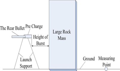
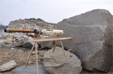
To select the appropriate boulder, the present test was performed in Big Island of Quanzhou, Fujian province, where main components of the rock are sedimentary rock. Fig. 3 demonstrates diagram and site map on set mode of blasting vibration test with TSCW.
The test blasted the boulder by self-developed TSCW whose initiation is delayed in order. And prime charge chose shaped charging structure which is optimally designed by Xu Haoming, et al. [11] 8701 explosions with density of 1.70 g/cm3 and total mass of 4.8kg was adopted. 0.48 kg of improved aluminum charge was selected as post bullet based on the requirement of smashing rocks and launch tube was improved by DZP11-80 launch tube individual distance air bomb.
In the large amount of field test and observation, a good correlation between damaging degree of blasting vibration and peak particle velocity was found and the relationship between vibration velocity and properties of the rock-soil medium was relatively stable [12]. Tests monitored vibration velocity with blasting vibration tester TC-4850 produced by Zhongke Measurement and Control Company. The tester has three parallel channels for monitoring vibration velocity in three directions; sampling rate is 1-50 kHz, frequency response ranges 0-10 kHz. Ride meter is widely used in engineering and its stability as well as accuracy can meet test requirements. The first-order differentiation and fast Fourier transform (FFT) of vibration data were realized through collecting vibration velocity curves at the different measuring points [13], vector-velocity time history curve of measuring points and relationship curve between vibration velocity, and frequency were shown. And transmission law of seismic wave was analyzed from the perspectives of amplitude, duration and frequency. According to situations of test area, which have the same charging structures and setting method and the distance from measuring points to blasting center ranges from 30 m to 150 m.
Fig. 3Diagram and site map on set mode of blasting boulder with TSCW and measuring point setting
4. Analysis on test data
Essential factors of blasting seismic wave are amplitude of vibration velocity, duration and frequency and monitoring of vibration velocity is most frequently adopted in engineering practice [14]. With monitoring of curves of BVV at measuring points along with analysis on peak particle’s velocity (PPV), VD and VF, transmission law of blasting vibration of blasting the boulder with TSCW was obtained, which could provide reference for blasting safety protection.
4.1. Analysis on PPV
From formation mechanism of seismic wave with blasting the boulder with TSCW, influence of post bullets charge can be ignored and the data can be analyzed and calculated by taking prime charge as single homogeneous explosion.
A large number of analysis results of measured data indicate that PPV can be expressed as a function of charge weight (), distance from blasting center (), rock and soil properties along traveling path of blasting wave and conditions at measuring points [15]. The widely used Sodev’s formula is as follow:
where is the scaled distance (m/kg1/3). and are the parameters describing the propagating media and measuring points.
Table 1BVV data of boulder barrier breaking (cm/s)
m) | (m/kg1/3) | PPV | |||
30 | 13.693 | 0.858 | 0.975 | 1.228 | 1.787 |
60 | 27.386 | 0.572 | 0.252 | 0.995 | 1.175 |
90 | 41.079 | 0.678 | 0.130 | 0.296 | 0.751 |
120 | 54.7726 | 0.061 | 0.029 | 0.125 | 0.142 |
150 | 68.465 | 0.022 | 0.023 | 0.115 | 0.119 |
The test monitored at measuring points at different distances to blasting center and Fig. 4 is the curve of vibration velocity at measuring points whose distances from charging center are respectively 30 m and 120 m. Based on the test field, PPV at measuring points with distances of 30 m-150 m from blasting center in three directions are shown in Table 1. From the Fig. 4 and the data of Table 1, it can be seen that particle velocity of measuring points in three directions varies numerically, and peak value of the single component will also vary in different blasting environments, time and frequency. So it is reasonable to choose square root from the square sum of three portions’ peak speed as the PPV:
Fig. 4Curve of BVV-Time R= 30 m
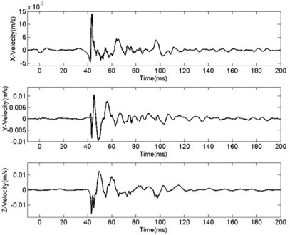
Fig. 5Curve of BVV-Time R= 120 m
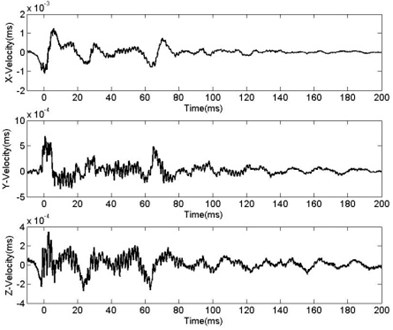
Fig. 6Changing curve of PPV with R
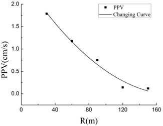
Fig. 7Fitting Curve of blasting the boulder
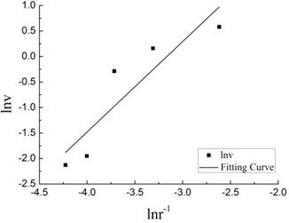
Table 2Processed data table of PPV and r
–2.617 | –3.310 | –3.715 | –4.003 | –4.226 | |
0.581 | 0.161 | –0.286 | –1.952 | –2.129 |
With , , being the peak particle velocity along three orthogonal directions , and [16, 17]. Therefore, to better predict blasting vibration, it may be most reasonable to evaluate with module of the . In the figure, peak vibration velocities in three directions are different and the maximum may be in any directions, so the analysis should be on resultant velocity for comprehensively discussing vibration velocity of three directions and avoiding influence of direction error in setting measuring points [18].
Propagation law of seismic in rock-soil is usually investigated by Sadev’s formula [19]. Fig. 6 indicates that with increase of distance from blasting center, vibration velocity decays exponentially and decay form coincides with Sadve’s Formula. In Table 2, the above data was processed by the method of least squares, and the data was fitted by MATLAB. Fig. 7 shows the fitting curve and the relationship between vibration, charging mass and between distance from blasting center:
4.2. Analysis on VD
Figs. 8-9 reveal that start and terminal time of particle are difficult to ensure. As vibration duration refers to duration of the whole process from measuring point starts movement to terminal time and record of duration is directly related to sensitivity of the test equipment. There hasn’t been a definition on duration that is universally agreed and it is commonly accepted that using the relative value of the maximum amplitude method. Selecting the largest component of the vibrating motion waveform moment , the vibration waveform decays to moment , .(where is the peak vibration vector in three directions and is the natural constant) [20]. Statistical list of of different measuring points is shown in Table 3 and gradually increases with the increase of distance from blasting center.
Fig. 8Curve of vibration vector velocity with distance of 30 m
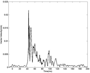
Fig. 9Curve of vibration vector velocity with distance of 120 m
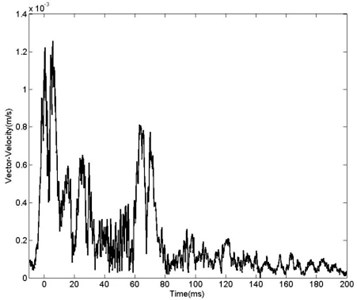
Table 3VD at different measuring points
(m) | 30 | 60 | 90 | 120 | 150 |
(cm/s) | 1.787 | 1.175 | 0.751 | 0.142 | 0.119 |
(cm/s) | 0.657 | 0.432 | 0.276 | 0.052 | 0.044 |
(s) | 0.018 | 0.058 | 0.073 | 0.093 | 0.097 |
There are wave, wave, wave and wave in seismic waves, among with wave transmits fastest, transmission of wave and wave is relatively slow and wave’s transmission slowest. With the increase of distance from measuring point and blasting center, different waves gradually get separate, thus operation time is longer. Analyzing vibration effects of TSCW from the perspective of duration, it is indicated that the further the distance from blasting center, the longer lasts duration of blasting vibration, which is consistent with general law that duration of rock blasting vibration increases with the increase of distance from blasting center [21]. Fig. 10 reveals that when the boulder is acted by tandem shaped warhead, curve of duration growth according to distance change is similar to form of binomial. With fitting data at measuring points, the relation between blasting vibration duration and distance from blasting center with three fitting methods can be concluded:
Fig. 10Relation between VD and R
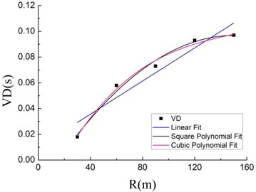
Using ORIGIN to fit the data, resulting in the relationship duration and distance of the blast center. Fitting correlation coefficients as shown in Table 4. By analyzing the correlation coefficient of three fitting methods can be drawn with the relationship between and by square polynomial fit not only good correlation, and a smaller standard deviation and less computation. Therefore, Eq. (6) is calculated to meet the needs of data analysis when the forecast .
Table 4The relative value of curve fitting
Correlation coefficient | |
Linear fit | 0.881 |
Square polynomial fit | 0.978 |
Cubic polynomial fit | 0.964 |
4.3. Analysis on blasting VF
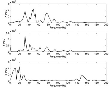
Obtained by FFT, curve in Figs. 11-12 show relationship between power spectrum diagram (PSD) and frequency in vertical direction with different distance from charging distance. According to Safety Specifications of Blasting Operation of China (GB 6722-2003), chamber blasting of reference data is smaller than 20 Hz when selecting frequency, deep hole blasting 10-60 Hz and shallow hole 40-100 Hz [22]. In general rock blasting, most energy of seismic wave is around 0-200 Hz [23, 24]. Cure of frequency and vibration velocity in Fig. 8 reveals that frequency range of seismic wave in this blasting is larger than that of general rock blasting. VF of tandem shaped blasting is in 0-300 Hz, with higher frequency and larger range in the near area. The main cause is that transmitting media of blasting area is rock and its blasting mode is the non-contact explosion near the ground. Comparison and analysis of curve of VF and velocity of 60 m and 30 m indicate that with increase of distance from charging center and larger damping in rock, high frequency component can get absorbed more easily, making range of VF gradually smaller, thus, high-frequency component obviously decreases and the low-frequency components relatively large. It also corresponds to the law that for transmission of seismic waves in rock-soil, transmission distance of high-frequency waves is relatively small and that of low-frequency waves large.
When VF is close to own frequency of buildings, side-effects are relatively larger. TSCW blasting boulders, when vibration velocity of the near area becomes larger, frequency becomes higher. Meanwhile, low seismic wave frequency of the far area is close to own frequency of buildings, but the seismic strength is weak, thus, vibrating side-effects of blasting seismic wave of the tandem warhead on buildings is smaller of those caused by general blasting of rock-soil. In setting tandem shaped warhead to blast boulders, people should consider the influence on surrounding environment to avoid damages caused by blasting vibration.
Fig. 11Curve of PSD- frequency R= 30 m
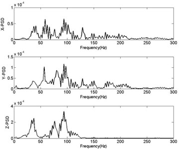
Fig. 12Curve of PSD- frequency R= 120 m
5. Discussions
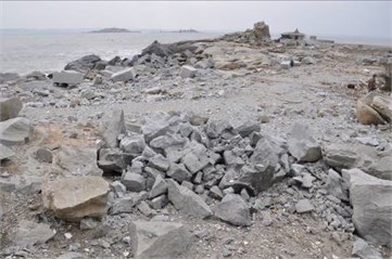
Mechanism of TSCW is: prime charge produces high-speed rot jet, penetrating the boulder and forming perforation with large depth and diameter. Along the passageway formed by penetration, blast bullets overcome the resistance and proceed to bottom of the target pre-open hole. The blast breaks the boulder to achieve the objective of breaking barriers. Main function of prime charge is forming passageway for explosion of post bullets in the boulder. Prime charge explodes in the air, explosion energy forms perforation together with air shockwave and seismic wave; post blast bullets explode when arriving at bottom of the target pre-open hole and explosion energy is mainly employed for breaking target. As there only exists contact between target and the ground, stress wave produced by blast causes reflection and projection at the contact surface, hence, energy of seismic wave formed on the ground almost can be ignored and hazardous effect produced by post bullets is mainly blast slung shot. Therefore, hazardous effects of blasting the boulder with TSCW are mainly shockwave, seismic wave and blast slung shot. Fig. 13 is the boulder before barrier-breaking, Fig. 14 shows the scenario after breaking-blasting with TSCW.
Fig. 13The boulder before blast
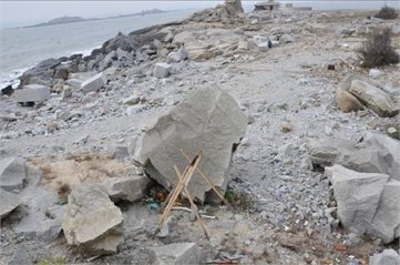
Fig. 14The boulder after blast
Killing effect of shockwave on people can be characterized by shockwave overpressure. Harmless overpressure of shockwave should be smaller than 0.0196 MPa. Universally acknowledged computing formula of shockwave peak value of charge blast in infinite air is:
In the formula, is distance from blasting center, with m as the unit; is quality of the charge and kg is the unit. is the maximum overpressure of the shockwave front with the unit of MPa. With the above formula, personnel safety distance of shockwave can be calculated as 16.5 m. Blast slung shot is caused by rock fragments tossed out by explosion gas and shockwave energy when blast bullets explode proceed into the boulder. Video of blasting test and statistical results of rock fragmentation suggest that thrown range of rock fragments is 24-26 m. When TSCW breaks barriers in earthquake disaster area, surrounding buildings are dangerous and seismic wave of blasting the boulder would cause secondary damage. Thus, if TSCW is applied in this case, blasting vibration damages should be strictly controlled.
Prime charge explodes in the air, producing seismic wave which attenuates slower than shockwave, but it has wider influence range. Blast vibration is monitored and transmission law of seismic wave of the blast is analyzed from the perspective of three elements of seismic wave. Analysis on vibration signals at measuring points at different distances reveals that seismic wave of breaking barriers mainly comes from explosion of prime charge, while blast of post bullets in the boulder almost produces no vibration signals. Vibration signals are analyzed, and it indicates that dominant frequency gradually decreases with increase of the distance, and vibration amplitude attenuates exponentially but duration gradually increases. According to GB6722-2003 [22], safety limit of blasting vibration of dangerous buildings is 1 cm/s, hence, safety distance of TSCW in earthquake disaster area should be controlled within 60 m. Through analysis, it is known that when adopting TSCW in earthquake disaster area, attention should be paid to hazardous effects caused by seismic wave, nevertheless, under the condition of battlefield environment, consideration should be focused on damages produced by air shockwave and blast slung shot. Adjusting setting distance of TSCW according to the use environment can help prevent hazardous effects.
6. Conclusions
TSCW as a new barrier-breaking system, which harm effects detailed study is necessary. By collecting and analyzing the vibration data, the following conclusions can be drawn:
1. Through analyzing the mechanism of seismic waves produced by TSCW, it has been concluded that when blasting boulders that have large contact area with ground, vibration influence of blasting post bullets on blasting vibration can be ignored and to predict blasting vibration only needs consideration on pre charging dose.
2. Transmission law of seismic wave produced by TSCW is similar to that of blasting inside rocks and predicting blasting vibration requires comprehensive analysis of the vector sum in three directions. By fitting formula with testing data, attenuation formula of BVV of the present test field with the tandem warhead is , and it attenuates faster than transmitted seismic wave strength in general rocks.
3. can be predicted by the Eq. (6). VF range of tandem warhead blasting is 20-150 Hz. Moreover, with increase of distance from blasting center, increases, frequency range decreases and centers in the low-frequency range but the strength attenuates larger, hence, vibration side-effects of blasting seismic waves of the tandem warhead on buildings are smaller than those of general soil-rock.
References
-
Xu H. M., Gu W.B., Huang H. Numerical simulation and experimental investigation on a shaped charge with new structure liner. Proceedings of International Conference on Mechanical Design, Manufacture and Automation Engineering, Phuket, Thailand, 2014.
-
Xu H. M., Gu W. B., Zeng Z., et al. Effect of Delay Time on Formation and Penetration of Tandem EFP. Chinese Journal of High Pressure Physics. Vol. 28, Issue 1, 2014, p. 79-85.
-
Weber P. W., Millage K. K., Crepeau J. E., Happ H. J., Gitterman Y., Needham C. E. Numerical simulation of a 100-ton ANFO detonation. Shock Waves, Vol. 25, 2015, p. 127-140.
-
Dewey M. C., Dewey J. M. The physical properties of the blast wave produced by a stoichiometric propane/oxygen explosion. Shock Waves, Vol. 24, 2014, p. 593-601.
-
Ronald P., Kim R. M., Anatol L. Explosion phenomena and effects of explosions on structures. Parts 1-3. ASCE Practice Periodical on Structural Design and Construction, Vol. 15, 2010, p. 135-169.
-
Gordon F. R., et al. Managing rock blasting work in urban environment. ASCE, Practice Periodical on Structural Design and Construction, Vol. 11, Issue 2, 2006, p. 86-92.
-
Donald G. A., Shahram T., Keith A., et al. Ground vibrations produced by surface and near-surface explosions. Applied Acoustics, Vol. 74, Issue 11, 2013, p. 1279-1296.
-
Lin D. C., Zhang Q., Bai C. H. Random property of ground vertical vibration velocity induced by near ground explosion seismic effect. Explosion and Shock Waves, Vol. 20, Issue 3, 2000, p. 235-240.
-
Ning J. G., Wang C., Ma T. B. Explosion and Shock Dynamics. National Defense Industry Press, Beijing, 2010.
-
Zhang Q., Lin D. C., Bai C. H., et al. Investigations of evaluating blast damage power to ground surface targets by explosion seismic effects. Explosion and Shock Waves, Vol. 22, Issue 1, 2002, p. 92-95.
-
Xu H. M., Gu W. B., Liu J. Q., et al. Numerical simulation and experiment study on explosion structure design of tandem shaped charge. Acta Armamentarii. Vol. 35, Issue 2, 2014, p. 170-175.
-
Li H. T., Lu W. B., Shu D. Q., et al. Study of energy attenuation law of blast-induced seismic wave. Chinese Journal of Rock Mechanics and Engineering, Vol. 29, Issue 1, 2010, p. 3364-3369.
-
Li X. B., Ling T. H., Zhang Y. P. Analysis of Blast Vibration Signals Theories and Methods. Science Press, Beijing, 2009.
-
Wei H. X., Chen S. H. Effects of main factors of blasting seismic waves on elastic-plastic seismic response of multistory masonry buildings. Explosion and Shock Waves. Vol. 31, Issue 1, 2011, p. 55-61.
-
Liang Q. G., An Y. F., Zhao L., et al. Comparative study on calculation methods of blasting vibration velocity. Rock Mechanics and Rock Engineering, Vol. 44, 2011, p. 93-101.
-
Dowing C. H. Blast Vibration Monitoring and Control. Prentice Hall, Englewood, NJ, 1985.
-
Luigi S. Theoretical derivation of a peak particle velocity-distance law for the predition of vibrations from blasting. Rock Mechanics and Rock Engineering, Vol. 42, 2009, p. 547-556.
-
Xie X. Q. Precision Blasting. Huazhong University of Science and Technology Press, Wuhan, 2010.
-
Orlenko L. P., Sun C. W. Explosion Physics. Science Press, Beijing, 2011.
-
Liang X. Q. Underwater Blasting Technology. Chemistry Industry Press, Beijing, 2013.
-
Li H. T., Shu D. Q. Influential factors analysis of blasting vibration attenuation law. Engineering Journal of Wuhan University, Vol. 38, Issue 1, 2005, p. 79-82.
-
Wang X. G., Xu T. R., Zhang Z. Y., et al. GB6722-2003 Safety Regulation for Blasting. Chinese Standard Press, Beijing, 2004.
-
Ling T. H., Li X. B. Laws of energy distribution in different frequency bands for blast vibration signals. Journal of Central South University of Technology, Vol. 35, Issue 5, 2004, p. 310-315.
-
Singh P. K., Roy M. P. Damage to surface structures due to underground coal mine blasting: apprehension or real case? Environmental Geology, Vol. 53, 2008, p. 1201-1211.
About this article

This work was supported by a Grant from National Defense Program and Natural Science Foundation of China, grant number BY209J033 and 2012BAK05B01. Their contribution to bringing this project to fruition is much appreciated. And high tribute shall be paid to Liang Ting, who has provided insightful comment on editing this paper. The authors would like to express their appreciations to the referees for valuable advices.
All authors belong to the same research team, have participated in the experimental study. Zhenxiong Wang and Wenbin Gu designed the experiment. Gu Wenbin proposed research ideas and Zhenxiong Wang wrote the paper. Liu Jianqing and Chen Jianghai performed the experiment. Jinglin Xu and Xin Liu helped to modify the paper. All authors have made an indispensable contribution to this article.
