Abstract
With the exploration and demand for the field of marine, underwater vehicles are used in deep water widely, however, there is a lack of research about underwater vehicles which are applied in shallow wary water. When underwater vehicles working in shallow wary water, they will be affected by the inrush current effect of shallow waters, so the research of underwater vehicles about anti current control becomes a meaningful item. But due to the high cost of underwater work, simulation and analysis to the inrush current online detection mechanism first, to determine the effects of surge phenomenon of underwater vehicles. Electromotor drives propeller to generate the flow, the detection mechanism is subjected to the impact of all directions. For some mechanical analysis of the inrush current online detection mechanism and analyzing the influence on the water inrush current when it moved in this paper, so we can reduce the effects of water inrush current on underwater vehicles in the subsequent experiments.
1. Introduction
With the development of economy, many resources on land are being exploited in succession, some are in danger and on the verge of exhaustion, this forces people to explore and exploit new resources. Ocean is the most potential space, is a strategic development base of all kinds of resources and will have a direct and great influence on the economy, humanity and society [1]. Underwater vehicles have increasingly gone beyond being laboratory curiosities to become an important tool for marine affairs. The underwater glider equipped with a variety of sensors can observe and acquire the temperature, salinity, turbidity, chlorophyll, oxygen content and current information about water in a wide range. Moreover, it has an important effect on the development of marine resources, disaster etc. Underwater vehicle has a good application prospect, this is also the reason for many years that so many countries are vigorously supporting and developing the underwater vehicle technology.
Underwater vehicles are very widely used. At the same time, with the intensification of global warming, environmental pollution has become serious increasingly, scientists have an urgent need to use a lot of underwater vehicles collect oceanographic data to detect changes in the environment. In our daily life, underwater vehicles can be used for pipes, container inspection, scientific research and teaching. In addition, because of the unknown nature of the underwater environment, using underwater vehicles, we can do some activities where people are difficult to go or that will cost a lot of money, such as checking up and detecting reactors and helping to dislodge the object and overhauling locks in hydroelectric power station. In the military, the applications in the underwater vehicles will reduce threaten by mine and reconnaissance in restricted areas. Similarly, underwater vehicles also play an important role in. shallow areas.
Underwater vehicle [2-6] has important potential application value and irreplaceable, and has aroused extensive attention of marine development community. However, the research of underwater vehicle is mostly used in deep water, but has little research on expansion of inrush current problems which caused by the river or the shallow of the river. This paper is based on preliminary work on the control and the application research of underwater vehicle, we research the anti-surge control technology of underwater vehicle in the shallow water of the river, to realize and guarantee the stability of the good state of motion and pose, fast control when performing tasks underwater. Usually, when underwater vehicles performing the task underwater or over-water, a certain flow speed and surge disturbances are unavoidable, including the mother ship and vessels that near the mother ship will cause a relatively severe surge. Sometimes a rotating vortex will affect the control of underwater vehicles. So there is necessary to make a closed loop anti-surge control research to underwater vehicles, especially to the credible control system.
In today’s world, the research methods of inrush current are very few, and most of them are software simulation and semi-physical simulation. Literature [7] based on AI Leaper presents a simple simulation of water wave method, which is easy to implement, it also can simulate many forms of waves, such as waves of lake, ocean waves and so on. Literature [8] combined with illumination model, the water wave is simulated by using the approximate value, and realized the water wave animation. Literature [9] based on the directional wave spectrum, the simulation of the deep water wave at different wind speeds is carried out by MATLAB, to provide technical support for the navigation of the underwater vehicle. The anti-surge control of robot technology in the shallow water of the river has almost nothing, and there is no more a mechanism can detect the state of flow of 360 degrees. Based on this situation, this paper puts forward a kind of inrush current online detection mechanism to fill this vacancy.
However, putting forward the inrush current online detection mechanism is not enough, this paper also analyzed the proper mechanics on the proposed mechanism. Mechanical analysis of the past confined which only construct a mathematical model of the system, and then use mathematical formulas to gradually pushed out to get conclusion, or use the bending moment diagram or diagram on the mathematical models to show the influence factors [10-14]. Those solutions can’t express the influence factors in every point clearly, these solutions are not intuitive and not comprehensive. Through this paper, the surge line detection device software ANSYS mechanical analysis, and the whole device surge disturbance trends and the role of the various points of force expressed through intuitive image size.
2. The design of the inrush current online detection mechanism
2.1. The whole idea of design of the inrush current online detection mechanism
This design in this paper can be used to detect the surge line 360 degree detection mechanism, of course, it must be used with multi-spiral simulation device and PC, so that it is easy to measure the required experiment data, further on-line detection mechanism inrush mechanical analysis, analysis of the impact of surge disturbances.
Fig. 1The whole block diagram
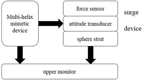
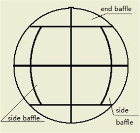
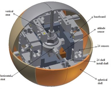
As shown in Fig. 1, which is the cooperative relationship between the three. Multi-helix mimetic is by means of the left servo motor, the paddles can be adjusted as desired angle and speed. Surge device on the right side, is the object of study, mainly consists of three important parts: the force sensor, attitude transducer and the sphere strut respectively; force sensor detects the effect of the inrush current disturbance in the process of movement, attitude transducer is used to compensate the position error in the process of movement, and the sphere strut is mainly supporting the part inside the inrush current online detection mechanism. The spherical sensor is composed of 24 pressure type strain sensor, which is composed of a mechanical structure. The outer sphere is divided into 24 pieces through the 3D printer processing. The reason for choosing the ball type as the mechanism appearance is that the ball has some typical characteristics, such as symmetry, compactness and so on.
2.2. The installation structure of the inrush current online detection mechanism
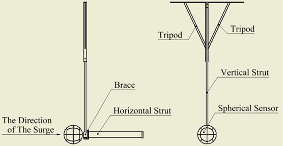
As shown in Fig. 2, is the installation diagram of the inrush current online detection mechanism. The spherical sensor is fixed by the method of internal and external thread, and the supporting frame is designed. The spherical sensor is fixed in the surge simulator. Spherical sensor and the brace is threaded through the internal and external connection; brace and horizontal strut is connected by bolts; brace and a vertical strut is through a fastening nut connection. When working, there will be hooked up to the four spiral simulation mechanism, were placed in the front, left and right and below. Put multi-angle surge disturbance on the inrush current online detection mechanism and measure different data.
Fig. 2The installation diagram of the inrush current online detection mechanism
2.3. The areal model of the inrush current online detection mechanism
As shown in Fig. 3, is the main section view of inrush current online detection mechanism. Fig. 4 is the top view of it, and the Fig. 5 is the left view of the inrush current online detection mechanism.
Fig. 3The main section view of inrush current online detection mechanism
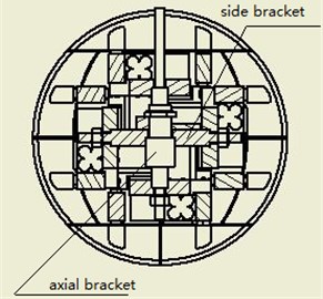
Fig. 4The top view
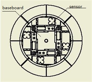
Fig. 5The left view
2.4. The design dimensions of the inrush current online detection mechanism
As shown in Fig. 6, vertical strut’s center line is axis, and axis are perpendicular in the side strut, as shown in Fig. 7.
Fig. 6The design dimensions of the inrush current online detection mechanism
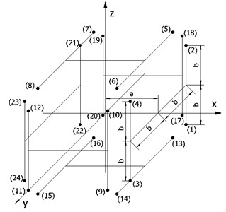
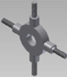
Fig. 7Schematic diagram of bracket
The 24 sensors’ coordinate are given in the above coordinates, where, “” is equal to 36 millimeters, “” is 27 millimeter. The coordinate data based on the above coordinate is (, , ). Then structure matrix, as shown below:
2.5. The 3D model of the inrush current online detection mechanism
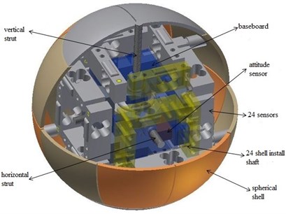
As shown in Fig. 8, is the 3D model of the inrush current online detection mechanism. Spherical sensor to imitate the head of the underwater vehicle, and the color of the spherical shell is not the same as just in order to highlight the spherical sensor composed by 24 pieces of spherical shell. In kind, 24 pieces of spherical shell is transparent, on the one hand, the spherical shell material is made of polyethylene and printed by 3D. On the other hand, the transparency of the spherical shell is more convenient to observe the state of the 24 sensors.
Fig. 8The 3D model of the inrush current online detection mechanism
a)
b)
3. Mechanical analysis of the inrush current online detection mechanism
Now the research of underwater vehicles is mostly used in deep water at present, but has little research on expansion of inrush current problems in the river or in shallow wary water. This paper research the anti-surge control technology of underwater vehicles in the shallow water of the river, to realize and guarantee the stability of the good state of motion and pose, fast control when performing tasks underwater. Usually, when they are performing the task underwater or over-water, a certain flow speed and surge disturbances are unavoidable, including the mother ship and vessels that near the mother ship will cause a relatively severe surge.
In order to ensure the stability of a good state of motion and pose, fast control when performing tasks underwater, in this paper, we use the Workbench software in ANSYS to make some mechanics analysis of the three-dimensional structure which is acquired previous, thus through the acquired finite element image to analysis the effect of the flow in the process of movement (the speed of the water flow and surge disturbance effects on the AUV).
3.1. Material selection about the inrush current online mechanism
Taking into account the specific circumstances of the forces underwater, we selected Polyethylene as the materials of spherical shell in the inrush current online detection mechanism. Polyethylene (PE) is a kind of semi crystalline thermoplastic material, which is very sensitive to the stress of the environment. Polypropylene is usually colorless solid translucent, odorless drug-free, and it possesses excellent cold temperature resistance. Polyethylene has good chemical stability, erosion resistance to most acid-base, good water absorption, and good electrical insulating properties. As to the 24 sensors’ materials, we choose the Aluminum Alloy. Aluminum alloy is one of the most widely used nonferrous metal structure materials, which has been widely used in aviation, aerospace, automotive, machinery manufacturing, shipbuilding and chemical industry. In order to make it clear and easy, the other parts of the mechanism, we choose Structural steel. The properties of materials are shown in Table 1.
Table 1Material properties
Material | Density (kg∙m-3) | Poisson’s ratio | Young’s modulus (Pa) | Bulk modulus (Pa) | Shear modulus (Pa) |
PE | 950 | 0.42 | 1.1e+09 | 2.2917e+09 | 3.8732e+08 |
Aluminum alloy | 2770 | 0.33 | 7.1e+10 | 0.9608e+10 | 2.6692e+10 |
Structural steel | 7850 | 0.3 | 2e+11 | 1.6667e+11 | 7.6923e+10 |
3.2. Finite element analysis for the inrush current online mechanism
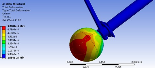
Because of the inrush current online mechanism only under the action of gravity when it has a static state in the water. According to different directions of inrush current, exerts a force on the underwater vehicles, in order to make corresponding adjustment on the different situations of hydrostatic acceleration magnitude and direction, we can acquire different deformation information. First pretreated the inrush current online detection mechanism: the geometric model is introduced, and the material properties are added and the mesh is divided. In the finite element analysis, dividing mesh is the key step, which influences the precision and speed. The second step is to solve the problem: load and constraint. As shown in Fig. 2, when the detection mechanism is used, the top end and the end part of the supporting frame are fixed on the fixed platform, so we can set the two place to the fixed constraint in the workbench analysis. The inrush current detection mechanism is an assembly, ignoring the internal friction between the parts, are set to Bold. Different loads will be discussed later. As shown in Fig. 9, is the inrush current online detection mechanism of positive stress’s current deformation image.
Because the inrush current online detection mechanism only under the action of gravity, that is to say it only by static hydraulic action, so do not consider applying the other force, do the adjustment can be in hydrostatic force, the density of water is set for 1000 kg/m2. In the forward force, axis acceleration is 9.8 m/s2, the rest is 0 m/s2. In Fig. 9, we can observe the size distribution of the inrush current online detection mechanism of the force in the water, the income graphics display that the data distribution coincide with the ideal expected, and at the same time shows its mechanical properties directly.
In addition, we measured data is the result of 24 sensors by income, so we also consider the elastic strain in this case, as shown in Fig. 10.
Fig. 9Total deformation image (1)
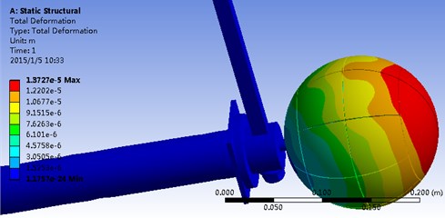
Fig. 10The equivalent elastic strain image (1)
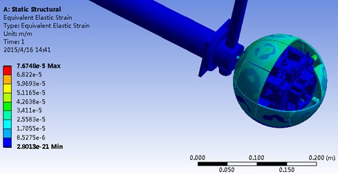
By the Fig. 10, we can see the force under the circumstance of each sensor. If the sensor or the various components of the force is too large, we also can make corresponding adjustment and change, which is a great help to design and implementation.
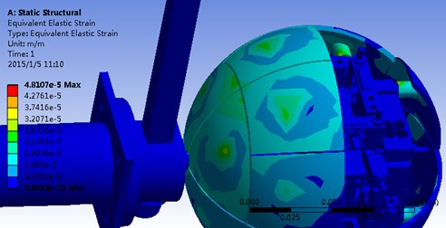
After the positive analysis of force, we also put the mechanical analysis of the inrush current online detection on 45 degrees force and lateral force, and acquire current deformation image of its. As shown in Fig. 11, is the inrush current online detection mechanism of lateral force’s current deformation image in this case, and axis acceleration is 9.8 m/s2, and the axis acceleration is 0 m/s2.
In this case, the maximum force component is a side plastic sheet shell. In order to see the stress situation of each sensor more intuitive, do Equivalent elastic Strain image, as shown in Fig. 12.
Fig. 11Total deformation image (2)

Fig. 12The equivalent elastic strain image (2)
Finally, we put mechanics analysis on 45 degrees force and acquire corresponding ANSYS image. As shown in Fig. 13, is the 45 degrees stress of the inrush current deformation image of its. In this case, , and axis acceleration is 9.8 m/s2. Fig. 14 is the Equivalent elastic Strain image.
Fig. 13Total deformation image (3)
Through the above the three groups of figures, we can see that the stress situation of inrush current online detection mechanism in different case clearly. If one part’s stress is too large, we can make the adjustment and change to get the required data on 24 sensors in the best condition.
In different inrush current directions, inrush current online detection mechanism has different directions of the force, so there will be different components to support this load and elastic deformation. Then three conditions will be concluded and compared in table I. As shown in this, there are the extreme stress and elastic deformation (the maximum and minimum) and corresponding component.
Fig. 14The equivalent elastic strain image (3)
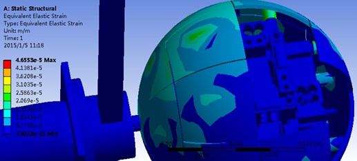
Table 2Different inrush current directions comparison
Positive stress | Lateral stress | 45 degrees stress | ||||
Total deformation | 1.1757e-024 m | Vertical strut | 3.4446e-025 m | Horizontal strut | 1.034e-025 m | Vertical strut |
1.3727e-005 m | Spherical shell | 6.0699e-006 m | Spherical shell | 5.3881e-006 m | Spherical shell | |
Equivalent elastic strain | 2.8013e-021 m/m | Brace | 2.8013e-021 m/m | Brace | 2.8013e-021 m/m | Brace |
7.6748e-055 m/m | Spherical shell | 4.8107e-055 m/m | Spherical shell | 4.6553e-055 m/m | Spherical shell | |
3.3. The real map of inrush current online detection mechanism
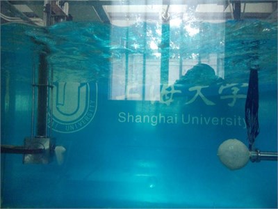
The inrush current online detection mechanism we designed has been applied to our experiment, is used for collecting data, and plays an important role. As shown in Fig. 15, is the real map of inrush current online detection mechanism.
Fig. 15The real map of inrush current online detection mechanism
3.4. The real map of inrush current online detection mechanism
In order to verify and test the performance of the spherical sensor and verify the accuracy of the above analysis, we do not only do the finite element analysis, but also put the model in the actual environment to measure data and use MATLAB to draw images.
Fig. 16Sensors’ position description

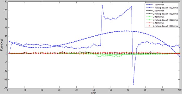
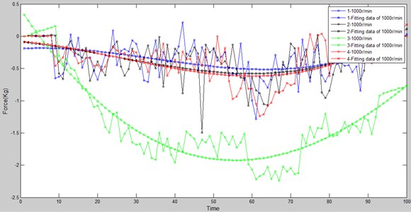
For the purpose to describe the signal sensor conveniently, 24 sensors are divided into 4 laps which is in accordance with the direction of the axis. As shown in Fig. 16. Since the sensor stress concentration region of axis of the first two laps, Fig. 17 and Fig. 18 are the data curves of single sensor in the first two circles. We collected the inrush current data and then making an analysis of the data by MATLAB. Fig. 17 and Fig. 18 are the images of different sensors at the same speed. The rotate speed of the propeller is 1000 rotations per minute (rpm). There are two lines of the same color, broken line is the real data collection, and the relatively smooth black curve is the corresponding fitting curve.
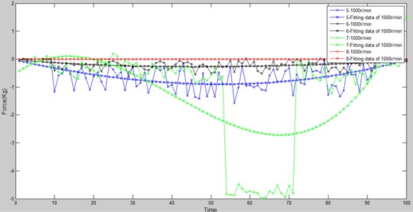
Figs. 17 and 18 are of the data corresponding to each label in Fig. 16. From the collection of the data, we can find that the four sensors of the first circle in the direction of the force is mostly positive. While the eight sensors of the second circle is the negative direction of the force. This is caused by the direction of the flow caused by the propeller. And the change trend of the sensors which are in the same circle are the same, which is consistent with the ANSYS simulation results we do.
Fig. 17First circle, data collection
4. Conclusion
When underwater vehicles work in shallow water, they will be affected by the inrush current effect of shallow waters, so the research of underwater vehicles about anti surge control becomes meaningful. But because of the high cost of underwater work, analyze the inrush current online detection mechanism first to determine the effects of surge phenomenon of underwater vehicles. In this paper, an on-line detection of spherical sensor for inrush current detection is designed firstly, and the force of each sensor in the whole mechanism is obtained through simulation of the mechanism. Then optimize the structure of the sensor to get the body in this article. The on-line detection mechanism has important significance for the study of the underwater vehicles inrush current. The inrush data is collected by the on-line detection mechanism, and the characteristics of inrush current are analyzed and the control algorithm is put forward based on the characteristics of the inrush current, to realize the fixed depth and stability control of underwater vehicles. The on-line detection mechanism which designed in this article lay an important foundation for the late study of current.
Fig. 18Second circle, data collection
a)
b)
References
-
Wei Yanhui, Peng Shengguo, Sheng Chao Motion stability control method for autonomous underwater vehicle. Journal of Huazhong University of Science and Technology. Vol. 42, Issue 2, 2014, p. 127-132.
-
Tian Y., Li W., Zhang A. Q. A simulation environment for deep-sea hydrothermal plume tracing with autonomous underwater vehicles. Robot, Vol. 34, Issue 2, 2012, p. 159-196.
-
Xiang X. B., Liu C. Synchronized path following control of multiple homogenous under actuated AUV. Journal of Systems Science and Complexity, Vol. 25, Issue 1, 2012, p. 71-89.
-
Kopman Vladislav, Cavaliere Nicholas, Porfiri Maurizio MASUV-1: a miniature underwater vehicle with multidirectional thrust vectoring for safe animal interactions. IEEE/ASME Transactions on Mechatronics, Vol. 17, Issue 3, 2012, p. 563-571.
-
Fischer Nicholas, Hughes Devin, Walters Patrick, et al. Nonlinear RISE-based control of an autonomous underwater vehicle. IEEE Transactions on Robotics, Vol. 30, Issue 4, 2014, p. 845-852.
-
Matsuda Takumi, Maki Toshihiro, Sakamaki Takashi, et al. Toward wide seafloor surveys using multiple autonomous underwater vehicles. Underwater Technology Symposium, IEEE International, 2013.
-
Petrantonakis Panagiotis C., Papoutsi Athanasia, Poirazi Panayiota Towards predicting persistent activity of neurons by statistical and fractal dimension-based features. Proceedings of the International Joint Conference on Neural Networks, IJCNN, 2013.
-
Vahedi Arman, Gorczyca Beata Predicting the settling velocity of Flocs formed in water treatment using multiple fractal dimensions. Water Research, Vol. 46, Issue 13, 2012, p. 4188-4194.
-
Li Kewen, Zhao Haiyang Fractal prediction model of spontaneous imbibition rate. Transport in Porous Media, Vol. 91, Issue 2, 2012, p. 363-376.
-
Ji Cuicui, Zhu Hua, Jiang Wei Fractal prediction model of thermal contact conductance of rough surfaces. Chinese Journal of Mechanical Engineering (English Edition), Vol. 26, Issue 1, 2013, p. 128-136.
-
Xiao Bo-Qi Prediction of heat transfer of nanofluid on critical heat flux based on fractal geometry. Chinese Physics B, Vol. 22, Issue 1, 2013, p. 14402.
-
Xu Peng, Qiu Shuxia, Yu Boming Prediction of relative permeability in unsaturated porous media with a fractal approach. International Journal of Heat and Mass Transfer, Vol. 64, 2013, p. 829-837.
-
Xiu Chunbo, Wanga Tiantian, Tian Meng Short-term prediction method of wind speed series based on fractal interpolation. Chaos, Solitons and Fractals, Vol. 68, 2014, p. 89-97.
-
Kirkwood W. J. AUV technology and application basics. OCEAN – MTS/IEEE Kobe Techno-Ocean, Kobe, Japan, 2008, p. 15-15.
About this article

The authors would like to acknowledge National Natural Science Foundation of China (No. 51005142), Innovation Program of Shanghai Municipal Education Commission (No. 14YZ010) and Shanghai Natural Science Foundation (No. 14ZR1414900) for providing financial support for this work.
