Abstract
The effect of welding residual stress on the vibration of underwater cylindrical shell is investigated. The welding residual stress of practical underwater structure, such as submarine, is widespread and complicate distributed. However, the earlier theoretical studies which mainly focused on the overall uniform distributed stress cannot be applied to deal with this practical vibration problem. In this paper, we offer a new theoretical analysis method aim at non-uniform distributed welding distributed stress. Based on the Flügge theory, considering the Fluid Structure Interaction (FSI), we derive the motion equations of the underwater cylindrical shell with welding residual stress. By means of a polynomial approximation and quadratic matrix linearization, we solve the nonlinear eigenvalue problem caused by the welding residual stress and FSI. Some numerical examples are used to validate our method and compare the welding residual stress-caused influence in the air and water.
1. Introduction
The welding is widely used in the construction of underwater structural engineering, such as the submarine assembly and closure. Due to the violent thermochemistry reaction there would produce and leave welding stress in the structure, and it exists widely in the submarine hull [1], [2]. As the basic form of the submarine, it is necessary to evaluate the free vibration of the underwater cylindrical shell with welding residual stress in order to prevent resonance.
The welding residual stress belongs to one type of initial stress in essence. Some research has been investigated about the influence of initial stress on dynamics. Doong [3] applied high order shear deformation theory to derive the initial stress thick plate vibration control equation, and compared this with reference data [4]. Liu studied the effect of hydrostatic pressure fields on the dispersion characteristics and power flow of cylindrical shell [5, 6]. Fuller and Fahy derived the fluid filled cylinder free vibration equation [7]. Zhang utilized the wave propagation method to analyze submerged and fluid filled cylinder free vibration characteristics [8, 9].
However, these efforts mainly focused on uniformly distributed stress, few studies have addressed welding residual stress, whose values change as the location varies. Gao studied the effect of welding residual stress on the thin plate’s natural frequency by experiments [10]. The Finite Element Method (FEM) is used as a solution of vibrational structure with welding stress, but it distributes mainly near the welding place and varies drastically there, so the elements near the welding have to be divided very finely. For the large scale structure with long welding joints, it will spend lots of time and calculation on mesh generation. Therefore, FEM is not appropriate for qualitative analysis.
Liu derived the motion equations of the cylindrical shell with wielding residual stress [11], but he did not consider the Fluid Structure Interaction (FSI) in [11]. For the underwater welding structure’s vibration problem, we have to consider the influence of welding residual stress and FSI at the same time. The problem become complex when consider these two factors both: firstly, since the welding residual stress is non-uniformly distributed, structural modes couple together. Single modes cannot be independently calculated and we have to solve the entire coupling equation. And the methods in [5, 6, 8, 9] are no longer appropriate. Secondly, when considering FSI, the problem becomes nonlinear which makes calculation more difficult. Liu’s method [11] cannot be applied to the underwater structure with welding residual stress, neither.
In this paper, based on the specific modes orthogonality found in [11], considering FSI, we derive the motion equations of the underwater cylindrical shell with welding residual stress. By means of a polynomial approximation and quadratic matrix linearization, we solve the nonlinear eigenvalue problem caused by the welding residual stress and FSI. Some numerical examples are used to validate our method and compare the welding residual stress-caused influence in the air and water.
2. Theory
2.1. Fundamental Equation
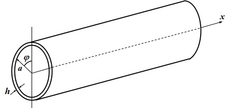
In this section, we review the vibration equation of welding cylindrical shell without considering FSI. The cylindrical shell is shown in Fig. 1
Fig. 1Cylindrical shell
Ignoring FSI, the vibration equation of cylindrical shell with welding residual stress is [11]:
where is the time; , are the axis and circumferential direction in cylindrical coordinate, respectively; , and are the normal stress and tangential stress, respectively; is the structure density; is the shell thickness; is the bending stiffness, is the Poisson’s ratio, is the Young’s modulus; , , and represent non-initial stress vibration; and , , and represent coupling between welding stress and displacement, their detailed expressions are listed in Appendix A1. Compared with the non-initial stress shell dynamic equation, there are added coupling terms , , and . When , , and are all zero, Eq. 1 becomes the classic shell motion differential equations.
Assume the boundary condition is simply supported, the displacement can be expressed in the series [12]:
where , , are the series coefficients, is the shell length, and .
Substitute Eq. (2) into Eq. (1), multiply on both sides of Eq. (1)-1, on both sides of Eq. (1)-2, on both sides of Eq. (1)-3, and make use of the trigonometric function’s orthogonality, to derive the dynamic equation of the welding structure:
where is the cylinder radius. Expressing the , , and integration terms in Eqs. (3-5) as , , and , which represent the effects of complex stress, and couple the structure modes:
2.2. FSI effect
To incorporate the FSI, we need to add the fluid load term, in Eq. (1)-3:
and assume that [13]:
where is the -order Hankel function of the second kind; , , is the speed of sound in the fluid, . By utilizing the velocity continuous condition, we can express the pressure with the displacement coefficient [8]:
Then Eq. 5 becomes:
We will only consider the normal stress in this paper. The welding residual stress can be expressed as:
where and are the axial and circumferential stress amplitude components, respectively; and and are positive integers.
Substitute Eq. (7) into , , and , then simplify by making use of the orthogonality. For simplicity, just give the derivation of here, we can simplify and in the similar way as follow. All the orthogonal properties needed for the derivation of , , are shown in Appendix A2. Substitute Eq. (11) into :
Take the first term of as an example to show the simplification:
Simplify Eq. (13) by making use of the product to sum formula and orthogonality below:
From Eqs. (14-19), only when:
Eq. (20) means the coupling just happen among specified modes.
We find that each mode is coupled with only a few specific modes, rather than all the other modes. Substitute the processed , , and into Eqs. (3-5), we can express the resultant equation in matrix form:
where ; ; is a sparse diagonal matrix that represents the non-initial stress part:
where the non-zero block matrices are:
and their elements are listed in Appendix A3; and is also a sparse non-diagonal matrix with non-zero block matrices:
whose elements are listed in Appendix A4.
When the stress distribution is complex, the stress can be expressed in the series as below:
where , are the series coefficients. Apply the same methods as above, we can establish a matrix equation:
where the complex matrix, , can also be expressed as a series:
Most distributions can be expressed as the series in Eq. (25). Hence, our method can be applied to deal with the vibration of underwater structure with practical welding residual stress distribution.
2.3. Free vibration
To solve the free vibration, the determinant of the coefficient matrix in Eq. (14) needs to be zero [13]:
When there is no stress in the structure, i.e., , Eq. (16) becomes the classical cylindrical shell free vibration characteristic equation. Otherwise, the structure mode will couple and change for . We can obtain the natural frequency and stress-caused coupled mode shape by solving Eq. (16). If we do not consider FSI, the -terms in are all , and the eigenvalue problem is linear and easy to solve. However, when considering FSI, the -terms in are not only , but also in Eq. (10). Hence, the -terms are not simply polynomials anymore because of the appearance of Hankel function, and the equation becomes a transcendental equation in the complex domain. Because of the coupling caused by complex stress matrix , the methods in [5, 6, 8, 9] are inappropriate. On the other hand, the Hankel functions in are related to the specific modes. Therefore, the problem here is a complex nonlinear eigenvalue problem.
We use polynomial approximation and quadratic matrix linearization to solve this nonlinear problem. First, apply Taylor expansion to expand the term at . Expanding to quadratic term can obtain enough accuracy:
where and are the Taylor coefficients. The nonlinear eigenvalue problem can be transformed into a Quadratic Eigenvalue Problem (QEP) after Tylor expansion:
where comprises of the constant terms in Tylor expansion and the complex stress matrix ; comprises of the first term coefficients in Tylor expansion; comprises of the quadratic term coefficients in Tylor expansion and the coefficients of . To solve this QEP, we use the first companion form for linearization [14, 15]. So Eq. (30) can be linearized into:
where is an identity matrix. Then the problem becomes a Generalized Eigenvalue Problem (GEP) which can be solved easily. The natural frequency and coupled mode shape can be obtained by solving the GEP.
3. Verification of the method validity
Firstly, we verify the validity of the presented method by a numerical example. Cylinder parameters are radius; length; shell thickness ; density ; Young’s modulus ; Poisson’s ration ; this cylinder is immersed in fluid, the fluid density ; sound velocity in fluid is , and the boundary condition is simply supported. The simpler the stress distribution is, the less the error from FEM result is. Therefore, in order to validate we choose a simple sinusoidal stress distribution. The stress distribution is shown in Figure 2. Our method is performed using MATLAB R2013. We calculated and compared the natural frequency of the cylinder using our method and FEM software Abaqus. In order to assume the welding effect into the FEM model, we need to rigid fix all the nodes of this cylindrical shell model, and exert the specified welding residual stress as shown in Figure 2 into this model to obtain the reaction forces and moments of every node. Then remove all the rigid fixations and exert the specified welding residual stress as well as these reaction forces and moments into the simply supported model together. In this way, we can construct the cylinder model with the specified welding residual stress distribution as shown in Figure 3, and the color represents the stress distribution. Assume three exists only -directional stress, , in the cylinder and the stress value only varies in the direction. The number of elements used in FEM is 1500. The results are listed in Table 1.
Fig. 2One-dimensional axial stress distribution
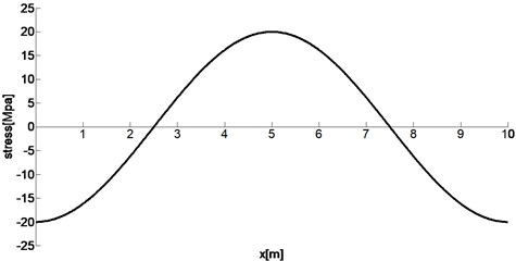
Fig. 3Cylindrical shell model
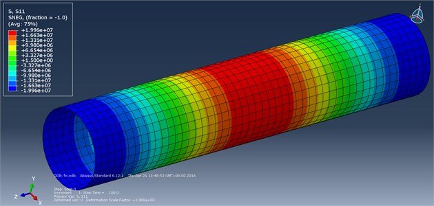
Table 1Comparison of natural frequency
Order | Natural frequency (Hz) | ||
Non-stress | Welding residual stress | ||
Our method | FEM | ||
1 | 7.69 | 5.85 | 5.83 |
2 | 9.52 | 6.53 | 6.69 |
3 | 17.43 | 15.70 | 16.16 |
4 | 18.40 | 16.84 | 16.98 |
5 | 19.19 | 18.48 | 18.98 |
6 | 20.91 | 19.20 | 19.18 |
7 | 26.91 | 26.73 | 27.26 |
8 | 28.41 | 27.17 | 27.51 |
9 | 31.72 | 30.59 | 30.99 |
10 | 32.76 | 30.61 | 31.25 |
Then we choose a practical welding stress distribution, the model is chosen as the same as the one in [11]. Cylinder parameters are radius ; length ; shell thickness ; density ; Young’s modulus ; Poisson’s ration ; the cylinder is immersed in water, and the boundary condition is simply supported. The welding FEM software Marc is used to obtain the welding stress. The welding type is manual metal-arc welding, the electric current is 180 A, the voltage is 30 V, and the welding velocity is 5 mm/s. The welding residual stress values are represented as the blue points shown in Figures 4 and 5. And the red line is the fitting curve by the specified series in Eq. 13. The number of series by our method is 140. The results are listed in Table 2.
Fig. 4Axial welding residual stress distribution
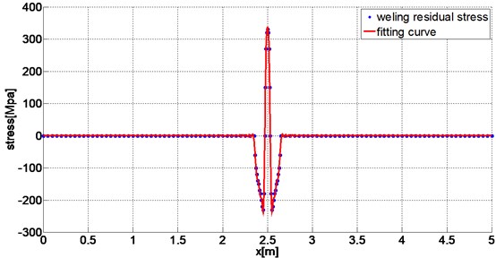
Fig. 5Circumferential welding residual stress distribution
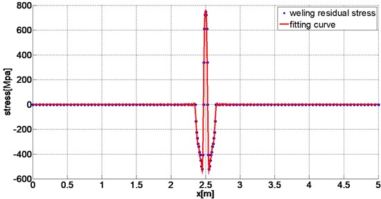
Table 2Comparison of natural frequency
Order | Natural frequency (Hz) | |||||
Without FSI | With FSI | |||||
Without welding residual stress | With welding residual stress | Difference (%) | Without welding residual stress | With welding residual stress | Difference (%) | |
1 | 52.07 | 47.97 | –7.88 | 31.10 | 28.66 | –7.84 |
2 | 101.86 | 102.63 | 0.76 | 57.34 | 57.42 | 0.14 |
3 | 108.25 | 103.27 | –4.60 | 70.44 | 66.78 | –5.19 |
4 | 128.24 | 130.98 | 2.14 | 82.29 | 80.24 | –2.48 |
5 | 137.15 | 135.87 | –0.93 | 83.58 | 81.07 | –3.00 |
6 | 181.54 | 178.81 | –1.50 | 118.49 | 119.82 | 1.12 |
7 | 204.32 | 199.57 | –2.32 | 142.05 | 137.12 | –3.47 |
8 | 211.28 | 213.94 | 1.26 | 146.96 | 141.64 | –3.62 |
9 | 229.78 | 228.65 | –0.49 | 159.92 | 155.17 | –2.97 |
10 | 263.02 | 260.93 | –0.79 | 161.23 | 159.52 | –1.06 |
As seen from Table 1, the results obtained by our method and those obtained using FEM basically match, which verifies the validity of our method. So our method can be applied to solve the vibration of underwater cylindrical shell with welding residual stress.
Seen from Table 2, the cylinder’s natural frequency differences caused by welding residual stress are similar between in the air and water, the greatest impacts both occur in the first order, 7.88 % and 7.84 %, respectively. And the impacts in 3rd order are also very obvious both in the air and water. But what worth noting is that the influence trend is not exactly the same between the air and water. For example, in the 4th, 6th, and 8th order the welding residual stress generate the opposite effect on natural frequency between air and water. So the influence of different distributed welding residual stress is worth studying further. Especially, nowadays high strength steel is widely used as submarine pressure hull. It has the high yield limit, so its amplitude of welding residual stress is higher than general structural steel. Consequently, welding residual stress in submarine has the greater impact on natural frequency.
At the same time, it can be seen from the results that FEM not only has a much larger DOF than our method but also has to carry out a complicated operation of applying the specified distributed welding residual stress. Moreover, if it is a large scale structure with long welding joints and we need to apply the practical welding stress (which distributes mainly near the welding joints and varies drastically there, and the elements near the welding joints have to be divided very finely), the amount of time and calculation will be huge by FEM. Therefore, our method is more appropriate for qualitative analysis, and it can help us study the rule of the welding stress-caused effects and clarify the essential relation between stress and vibration more explicitly and quickly.
4. Conclusions
Welding is widely used in engineering, and there often exists welding residual stress in underwater structures such as submarine, subsea pipeline, underwater riser and so on. However, the influence of welding residual stress on underwater structure vibration is often ignored. In this paper, we propose a new analytical method aim at non-uniform distributed welding residual stress. Based on the Flügge theory, we consider the FSI, put the stress influence into the vibration equation and obtain the motion equations of underwater welding cylindrical shell. By means of a polynomial approximation and quadratic matrix linearization, we solve the nonlinear eigenvalue problem caused by the welding residual stress and FSI. The presented method is validated by some numerical examples.
The proposed analytical method can be applied to solve the vibration of structure with not only welding residual stress but also arbitrary non-uniform distributed stress, supplementing an earlier study which focused mainly on the overall uniform distributed stress. So it has a wider range of applications than the previous analytical methods.
By the proposed method, we can do a more accurate vibration prediction which considering the welding effect. At the same time, it is more appropriate to do some qualitative analysis than FEM, which requires lots of time and calculation on mesh generation and stress exerting near the welding joints especially for large scale structures. What’s interesting, since our method can be applied in the condition that the stress distribution changes frequently, so it can help to find the optimal welding stress distribution in combination with some optimization algorithms. Which means it can help to search for the optimal welding position and parameters in order to obtain the best vibration performance. Also, because of conveniently comparing the influence of different located damage-caused stress, our method has some prospects in the damage identification in welding areas. In the future research, more detailed analysis and comparisons about the influence of different distributed stress will be conducted. The influence law of the stress is worth studying further. We will try to apply this method in more practical engineering applications, such as vibration-based welding optimization and damage identification.
References
-
Li L. B., Pan G. S., Wan Z. Q., et al. Numerical simulation and experiments study of welding residual stress of the cone-cylinder pressure hull of high tensile strength steel. Journal of Ship Mechanics, Vol. 14, Issue 10, 2010, p. 1143-1150.
-
Hong J. B., Du Z. M., Hou H. L., et al. Experimental study of residual stress in girth weld of large pressure hull. Ship Engineering, Vol. 28, Issue 5, 2006, p. 14-18.
-
Doong J. L. Vibrations and stability of an initially stressed thick plate according to a high-order deformation theory. Journal of Sound and Vibration, Vol. 113, Issue 3, 1987, p. 425-440.
-
Brunelle E. J., Robertson S. R. Vibrations of an initially stressed thick plate. Journal of Sound and Vibration, Vol. 45, Issue 3, 1976, p. 405-416.
-
Liu Z. Z., Li T. Y., Zhu X., Zhang J. J. Effect of hydrostatic pressure on input power flow in submerged ring-stiffened cylindrical shells. Journal of Ship Mechanics, Vol. 15, Issue 3, 2011, p. 301-312.
-
Liu Z. Z., Li T. Y., Zhu X., Zhang J. J. The effect of hydrostatic pressure fields on the dispersion characteristics of fluid shell coupled system. Journal of Marine Science and Application, Vol. 9, Issue 2, 2010, p. 129-136.
-
Full C. R., Fahy F. J. Characteristic of wave propagation and energy distribution in cylindrical elastic shells filled with fluid. Journal of Sound and Vibration, Vol. 81, Issue 4, 1982, p. 501-518.
-
Zhang X. M. Frequency analysis of submerged cylindrical shells with the wave propagation approach. International Journal of Mechanical Sciences. Vol. 44, Issue 7, 2002, p. 1259-1273.
-
Zhang X. M., Liu G. R., Lam K. Y. Coupled vibration analysis of fluid-filled cylindrical shells using the wave propagation approach. Applied Acoustics, Vol. 62, Issue 3, 2001, p. 229-243.
-
Gao Y. Y., Su Z. X., Jiao Q. Y., et al. Influence on the natural frequency of component with residual stress. Journal of Mechanical Strength. Vol. 24, Issue 2, 2002, p. 289-292.
-
Liu Y., Chen L. Y. The effect of weld residual stress on the free vibrational characteristics of cylindrical shell through the analytical method. Journal of Vibroengineering, Vol. 18, Issue 1, 2016, p. 334-349.
-
He Z. Y. Structural Vibration and Radiation. Harbin Engineering University Press, Harbin, Helongjiang, China, 2001.
-
Junger M. C., Feit D. Sound, Structures and Their Interaction, Second Edition. MIT Press, Cambridge, Massachussetts, London, England,1986.
-
Kirkup S., Amini S. Solution of the Helmholtz eigenvalue problem via the boundary element method. International Journal for Numerical Methods in Engineering, Vol. 36, Issue 2, 1993, p. 321-330.
-
Giordano J., Koopmann G. State-space boundary element-finite element coupling for fluid-structure interaction analysis. The Journal of the Acoustical Society of America, Vol. 98, Issue 1, 1995, p. 363-372.
Cited by
About this article

The work presented in this paper was supported by the Fund of State Key Laboratory of Ocean Engineering (Grant No. 1507).
