Abstract
When a wheel rolls to a flat, it can generate the impact force several multiples larger than that generated at the common time. The paper established a wheel-rail coupling vibration model with wheel flat, and vibration acceleration responses of the rail was computed. The computational result was then compared with the experimental result. Good consistency between simulation and experiment indicated that the finite element model is reliable. Then, based on the finite element model and boundary element model, the paper established a structural-acoustic coupling boundary element model and computed the radiation noise of wheel-rail under effects of wheel flats. Results show that: the wheel flats were an important reason for wheel rail impact noises, impact noises of wheel flats were mainly concentrated in frequency bands of over 250 Hz, and impact noises of wheel flats were closely related with wheel flat length, quantity of wheel flats as well as running speeds. With the increase of these parameters, the radiation noise of wheel flats would be increased correspondingly.
1. Introduction
In recent years, the high-speed railway has obtained rapid development. Because of application of advanced anti-skid and anti-idle technologies in high-speed trains, abrasion between wheels and steel rails has been reduced to a low level, but wheel abrasion still cannot be avoided. Wheel abrasion will bring damage to steel rail and sleeper, etc. Wheel flat is a general term for steel rail failures generated from periodical wheel clashing, that were caused by tread abrasion, stripping, defects and other factors which can influence wheel rolling roundness [1]. Wheel flats reduce service life of wheels and rails, increase energy consumption and railway maintenance cost, and may also lead to sharp rise in axle temperature. In addition, when wheels roll to the flats, they may generate impact force which is several multiples larger than that generated at the common time. Therefore, the noise radiated from wheel flats to the train surface will also be very huge.
At present, a lot of researches have been carried out to wheel flats and have also obtained some achievements. Zhai took excitation models such as wheel flats as excitation sources and input them into a train-rail coupling system model, obtaining numerical solutions which were consistent with experimental results. Zhai also researched the vibration regulations of wheel-rail impact force generated from old abrasion along with the running speed, finding that two peaks of wheel-rail impact force appeared within the scope of 0 km/h-200 km/h, where one peak appeared within the low scope of 30 km/h-40 km/h, the other peak appeared within the scope of 140 km/h-160 km/h, while the scope of 140 km/h-200 km/h was exactly the target speed of existing high-speed trains [2]. Researches of Zhai and Lyon focused on interaction force between trains and rails. However, vibrations were the source of noises. Their work has laid a foundation for research of wheel-rail impact noises. Wang [3] recognized wheel flats by the electric signal detection method and could obtain depth of wheel flats, but the method was not applicable to seamless steel rail routes. Gao [4] detected wheel flats by neural network algorithm which was improved by genetic algorithm, while the detection accuracy was improved compared with traditional detection methods. Vittorio [5] researched fault identification of wheel flats by wavelet transform due to its property of variable time-frequency resolution, which overcomes limitations of classical time-frequency approaches. Bian [6] used finite element method to research the impact force of sleeper under wheel flat effects and further analyzed influences brought by train speed and static loads on wheel flat impact force, but the research course was not verified in experiments. Xu applied dynamic theory of train-rail vertical coupling as well as acoustic radiation theories to establish a forecast model of wheel-rail rolling noise, preliminarily discussing wheel-rail impact noise [7].
However, above researches mainly focused on how to recognize wheel flat failures and discussed wheel-rail impact force caused by wheel flats, while impact noises caused by wheel flats were rarely researched. Yang [8] established a theoretical model of train-rail coupling vibration and computed impact noises caused by wheel flats, but the computational results were not verified by experiments. In addition, the theoretical model still had some deviation from actual situations. Based on previous researches, this paper built train–rail coupling vibration model using the finite element method [9, 10]. Acceleration responses of rail vibration were computed and compared with the experimental results to verify the reliability of the numerical computation model. Based on the finite element model and boundary element model [11, 12], the structural-acoustic coupling model was built and the wheel-rail radiation noise under the impact of flats was computed.
2. Theoretical analysis
The rail coupling vibration system is composed of two subsystems including the vehicle subsystem and the rail subsystem. The vehicle subsystem is composed of vehicle bodies, frame, wheel-sets and suspension devices. Assuming that the train is running along the rail at a constant speed, the rail subsystem is composed of the steel rail, sleeper and ballast, etc. The steel rails are considered as infinite long beams. In terms of sleeper and ballast, only the degree of freedom of vertical motion is taken into account instead of that of transverse and torsional motions. Wheel-rail normal force is determined by Hertz’s “nonlinear elastic contact theory”.
In the system, vehicle bodies, bogies, wheel-sets, sleeper and ballast are regarded as a rigid body. Suspension devices are seen as springs and damping elements. Its equations of motion are second order ordinary differential equations. The steel rail is a multi-mode system, whose equations of motion are often higher order partial differential equations. In order to make numerical integration, Ritz method is normally used on partial differential equations. Regular function and canonical coordinate are used to form ordinary differential canonical equations. Therefore, the vehicle-rail coupling dynamics vibration system can be uniformly expressed as follows:
where , and are mass matrix, damping matrix and stiffness matrix, respectively. , and are acceleration vector, velocity vector and displacement vector, respectively. is force vector. The excitory input for the system is Sato’s roughness spectrum and the relative displacement of the wheel flat.
The vibration velocity is obtained through numerical computation and then the wheel force spectrum is input into the finite element
equation to compute the speed response. Finally, the speed spectrum of wheels, rails and sleeper can be obtained through Fast Fourier Transform, which is the key to the next step of wheel-rail noises.
When the vehicle passes, the sound field beside a railway can be described by average sound pressure levels. Average sound energy is defined as the mean square of the sound energy radiated by the vehicle when it passes a testing point towards the passing period. In order to convert vibrations of a wheel-rail system into a noise level beside the railway, it is necessary to discuss wheels, steel rail and sleeper separately. In general, wheel sound radiation is deemed as overlaying of a series of point sound sources which pass the observation point; while steel rail and sleeper can be deemed as a linear sound source which has a finite length and passes the observation point.
Fig. 1Computational diagram of average noise during vehicle passing
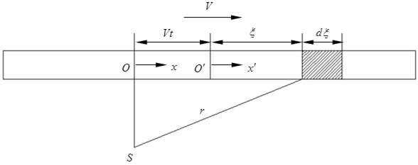
As shown in Fig. 1, the steel rail is deemed as a linear sound source. The total length of linear sound source is set to be . The vertical distance between the observation point and the rail center line is . is an absolute coordinate. The linear sound source moves along axis at the speed of . is an coordinate axis fixed at the linear sound source center , and moves with the linear sound source. is a micro-segment on the linear sound source, which is far from the linear sound source center. is the linear distance between the micro-segment and the observation point at the moment :
Power spectrum density of the linear sound source can be expressed by the following formula:
where: is sound radiation ratio. is sound impedance rate, in the normal temperature and standard atmospheric pressure, 420 Ra. is the valid surface area of sound radiation of steel rail per unit length, only vertical vibration of steel rail is considered, so that the surface area of sound radiation of steel rail per unit length is twice the sum of rail top width and rail bottom width , namely . is the mean square of 1/3 octave vibration speed of the steel rail in the vertical direction at the point of the linear sound source. It can be determined by the following formula:
where: is the power spectrum density function of vibration speed at the point. and respectively are top limitation frequency and bottom limitation frequency of the frequency band. The sound pressure square of observation point at the moment is shown as follows:
Within the duration , the average sound pressure can be expressed by the following formula:
By Eq. (3), we can obtain . It is substituted into Eq. (7) together with Eq. (2), so that the following formula can be obtained:
where: is the total radiation area of linear sound source, , is the mean value of steel rail vibration speed in space and time domains, namely the average value of the vibration speed mean squares at each point on the steel rail are computed along the steel rail length.
The sleeper can also be deemed as a linear sound source, so that the sound pressure square can be obtained by a similar method, as shown below:
where: is the total radiation area of sleepers joining the vibration, . is the total quantity of sleepers joining the vibration, is the bottom width of sleeper, is effective supporting length of sleeper. is the average values of sleeper vibration speed in space and time domains.
Sound radiation of wheels is deemed as overlaying of a series of point sound sources which pass the observation point. The computational formula is as follows:
where: is axial radiation area of a wheel, is radial radiation area of a wheel tread, is the mean square of wheel radial vibration speed.
Through comprehensive analysis of sound radiation of steel rails, sleeper and wheels, the wheel-rail noise at the position which is far away from the rail center line is obtained as follows:
3. Finite element model and experimental verification
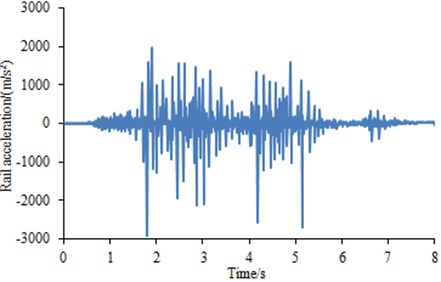
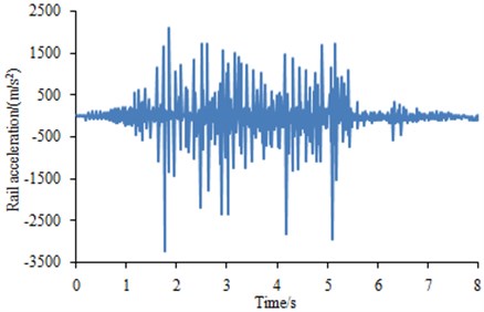
Experiments were conducted on a full scale wheel test platform. A full size freight wheel loads a 1.5 m long piece of rail attached to a carriage moved back and forth by hydraulic cylinder. Vertical loads up to 100 t and the lateral loads were 0. Length of the wheel flat was 40 mm. Vibration acceleration sensors were arranged on the steel rail to test vibration impact responses generated during rolling of wheels along the steel rail. Then, vibration signals measured by the acceleration sensors were input into multi-channel data collection equipment and then further input into Pulse software for post-processing to obtain the vibration acceleration of steel rails. The testing duration was 8 s. Each experiment was repeated for 3 times. Average value of three times was computed, as shown in Fig. 2. It was shown in Fig. 2 that the vibration acceleration had many peaks because coupling vibration was generated between wheels and rails during vehicle running.
The 3D model was transferred to the HYPERMESH software and elements with SOLID45 8-nodes were obtained shown in Fig. 3. Mesh at contact locations was refined very well to accurately model the contact region. FE model mesh was obtained with a total of 216871 elements and 256393 nodes. The material was steel with Poisson’s ratio of 0.31, density of 7800 kg/m3, and elastic modulus of 2.1e11. Wheels got contact with the steel rail closely, while the lower part of steel rails was completely restrained and fixed. Under total vertical load of 80 ton per total of 8 wheels in a wagon, resulting to 10 ton per wheel is applied. Wheels are assumed to operate on a flat and straight path; therefore, lateral loads to the system are ignored. Rotation boundary conditions are applied in the wheels to make them move along the wheel rail.
Fig. 2Rail vibration acceleration test values
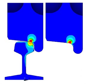
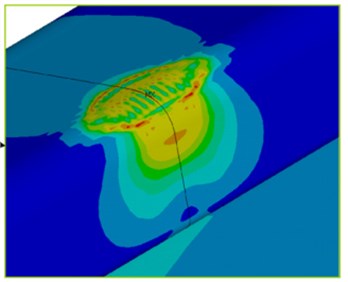
Contact stress between wheels and steel rails could be obtained according to the finite element model and boundary conditions, as shown in Fig. 4. It is shown in Fig. 4 that the stress was largest at the contact point between wheels and steel rails, while the stress spread all around along the contact point.
Fig. 3Finite element model of rail and sleeper
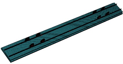
Fig. 4Contact stress between wheels and steel rails
Through the finite element model, the rail’s vibration response under the impact of wheels was obtained as shown in Fig. 5. It can be seen from the comparison between Fig. 2 and Fig. 5 that the computational values were generally larger than the experimental values, but the overall trends and peaks were basically consistent, which showed that the wheel-rail coupling computation model was reliable and can be used for the subsequent analysis.
Fig. 5Simulation values of rail vibration acceleration
4. Boundary element model
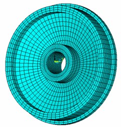
If the surface mesh of the finite element model was directly used, the computational time will be very long and the precision of the computational results will be decreased. Therefore, based on the geometric model, meshes were re-generated as shown in Fig. 6 and Fig. 7. Then, the boundary element and finite element models were imported into Virtual.lab and the tool in the software for checking element and node number conflicts was used to clear elements and nodes with problems in case of affecting the computational results. Wheels were coupled with the rail. An acoustic field point mesh was established. The final model was shown in Fig. 8. Additionally, the computational results of the finite element were directly mapped into the boundary element mesh so that the latter could directly obtain all features of the finite element. Finally, the wheel-rail impact noise could be directly computed with the software in 1/3 octave. Contours of acoustic field points under frequencies of 100 Hz, 500 Hz and 1000 Hz were extracted, as shown in Fig. 9. It is shown in Fig. 9 that when the analyzed frequency was 500 Hz, surface sound pressure of the high-speed train was mainly influenced by wheels; with continuous increase of the computational frequency, the surface sound pressure of the high-speed train was mainly influenced by the rail and presented an obvious periodical tendency.
Fig. 6Rail and sleeper boundary element mesh
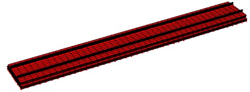
Fig. 7Wheel boundary element mesh
5. Impact noise generated by wheel flats
The impact of wheel flats on wheel-rail and the impact noise because of the increased train speed have gradually been researched. The following computed and simulated the influence on wheel-rail noises from the length of wheel flats, the number and train speeds.
Fig. 8Boundary element model of wheel-rail coupling vibration
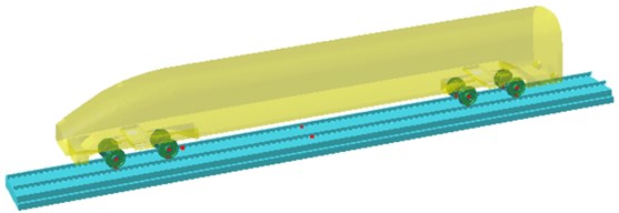
Fig. 9Contours of surface sound pressures of the high-speed train
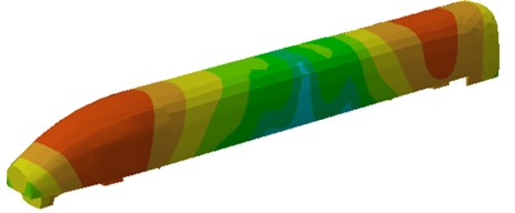
a) 100 Hz
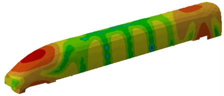
b) 500 Hz

c) 1000 Hz
5.1. Effects of wheel flats on wheel-rail noises
Fig. 10-13 showed the change of wheel-rail noises under the impact of wheel flats when vehicle travels at a speed of 150 km/h. It can be seen from Fig. 10-12 that the effects of wheel flats on wheels, rails and sleeper radiation noise were mainly concentrated in frequency band over 250 Hz within which the radiated noise increased due to the existence of wheel flats. The radiated noise was almost not affected within frequency band below 250 Hz. Fig. 13 showed the effects of wheel flats on total wheel-rail noises and it can be seen that the noise energy generated by flats mainly concentrated in the middle and high frequency bands.
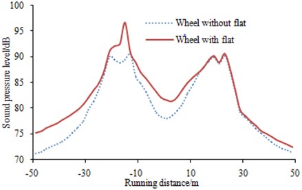
The vehicle was running back and forth, and time-history curve of the vehicle wheel-rail noise was recorded, as shown in Fig. 14. It can be observed that wheel flats largely increased the radiated noise of wheel-rail within certain running distance and the maximum value can reach 5 dB. Therefore, wheel flats greatly affected the vehicle running.
Fig. 10Effects of wheel flats on wheel noise
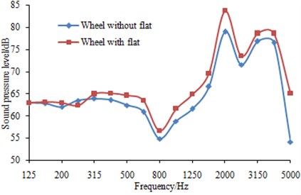
Fig. 11Effects of wheel flats on rail noise
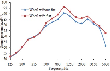
Fig. 12Effects of wheel flats on sleeper noise
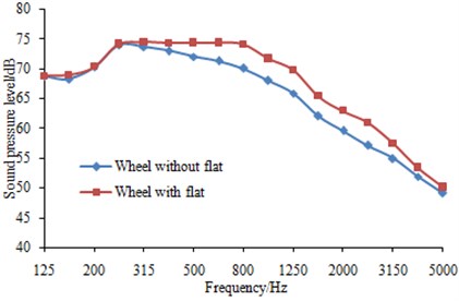
Fig. 13Effects of wheel flats on wheel-rail noise
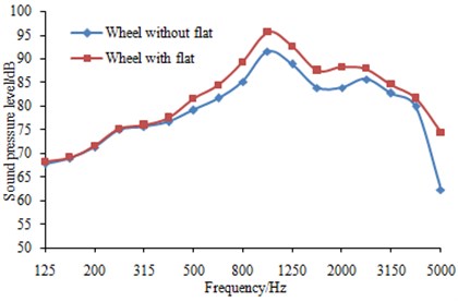
Fig. 14Time-history curve of wheel-rail noises
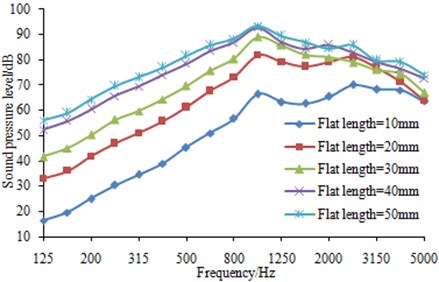
5.2. Effects of flat length on wheel-rail noises
The wheels were running on the rail at a speed of 150 km/h and different flat lengths were set respectively on the wheels to observe the change regulation of wheel-rail noises. Results were shown in Fig. 15. It was shown in the figure that longer flat length generated higher sound pressure levels of wheel-rail impact noises. Besides, the peak noise on each wheel-rail radiated noise curve generated by different flat lengths was around 1000 Hz. This can be explained as the change of flat length did not change the wheel vibration mode and thus the coupling vibration between wheels and rails did not change. However, when flat length was increased to a certain value, its effect on wheel-rail noises was not obvious. As can be seen from this figure, when the length was increased from 40 mm to 50 mm, the radiated noise change was not obvious and the maximum was 3 dB, while in some frequency band, the radiated noise generated by flats of 40 mm was even greater than that generated by flats of 50 mm.
Fig. 15Effects of flat length on wheel-rail noise
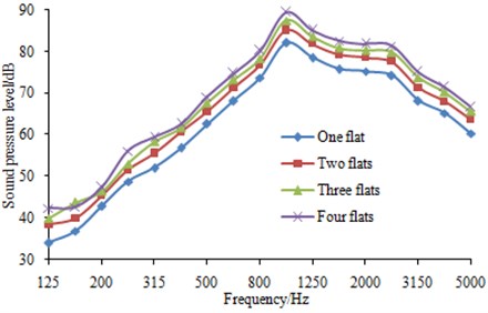
5.3. Effects of flat number on wheel-rail noises
The wheels were running on the rail at a speed of 150 km/h and different flat numbers were set on the wheels to observe the change regulation of wheel-rail noises. Results were shown in Fig. 16. It can be observed from the figure that wheel-rail radiation noises gradually increased with the increase of the number of wheel flats, but it is not as obvious as that generated by flat length. In addition, the peak noise on each wheel-rail radiated noise curve generated by different flat numbers was around 1000 Hz. This can be explained as the change of flat number did not change the wheel vibration mode and thus the coupling vibration between wheels and rails did not change.
Fig. 16Effects of flat number on wheel-rail noise
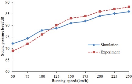
5.4. Effects of running speed on wheel-rail noises
The wheels were made with only one flat and the flat length was set as 40 mm to study wheel-rail radiation noises at different running speeds. The computational results were compared with the experimental results as shown in Fig. 17. As can be seen from Fig. 17, wheel-rail radiation noises were increased with the increase of running speeds. The main reason was that the impact between wheels and rail was intensified when speed increased under flats, which resulted in the increase of impact noise. In addition, the consistency between the simulation and experiment was also good, and the computational model and results were reliable.
Fig. 17Effects of running speed on wheel-rail noise
6. Conclusions
Wheel-rail coupling vibration model with flats was built and the vibration acceleration response was computed and compared with the experimental results. The good consistency indicated that the finite element model was reliable. Then, based on this finite element model and boundary element model, wheel-rail structure-acoustic model was built and wheel-rail radiation noise under the impact of wheel flats was computed. The results showed that impact noises generated by wheel flats were mainly concentrated in the middle and high frequency band over 250 Hz. And it was almost unaffected when the analyzed frequency was below 250 Hz. The increases of flat length and number would both increase wheel-rail impact noises, but the effect of flat number was not as obvious as that of flat length. In addition, the peaks of wheel-rail noises affected by flat length and flat number were around 1000 Hz because the change of flat length and number would not change the wheel vibration modes and thus the coupling vibration between wheels and rails did not change. With the increase of speed, wheel-rail radiation noises generated by flats would also increase.
References
-
Sackfield A., Dini D., Hills D. A. Contact of a rotating wheel with a flat. International Journal of Solids and Structures, Vol. 44, 2007, p. 3304-3316.
-
Zhai W. M. Coupling Dynamics of Vehicle/Rail. China Science Publishing, Beijing, 2007.
-
Wang F. C., Chi B. Q. On the on-line automatic detection method of flat wheel. Urban Mass Transit, Vol. 9, Issue 1, 2006, p. 31-33.
-
Gao R. P., Shang C. Y., Jiang H. A fault detection strategy for wheel flat scars with wavelet neural networks and genetic algorithm. Journal of Xi’an Jiaotong University, Vol. 47, Issue 9, 2013, p. 88-91.
-
Belotti V., Crenna F., Michelini R. C., et al. Wheel-flat diagnostic tool via wavelet transform. Mechanical Systems and Signal Processing, Vol. 20, Issue 8, 2006, p. 1953-1966.
-
Bian J., Gu Y. T., Murray M. Numerical study of impact forces on railway sleepers under wheel flat. Advances in Structural Engineering, Vol. 16, Issue 1, 2013, p. 127-134.
-
Xu Z. S., Zhai W. M. Study on excitation model for wheel/rail impact noise. Noise and Vibration Control, Vol. 4, 2007, p. 86-90.
-
Yang X. W., Zhai W. M. Wheel/rail impact noise due to wheel flats. Journal of Vibration and Shock, Vol. 28, Issue 8, 2009, p. 46-49.
-
Telliskivi T., Olofsson U. Contact mechanics analysis of measured wheel-rail profiles using the finite element method. Proceedings of the Institution of Mechanical Engineers, Part F: Journal of Rail and Rapid Transit, Vol. 215, Issue 2, 2001, p. 65-72.
-
Zhao X., Li Z. The solution of frictional wheel-rail rolling contact with a 3D transient finite element model: validation and error analysis. Wear, Vol. 271, Issue 1, 2011, p. 444-452.
-
Sheng X., Jones C. J. C., Thompson D. J. Prediction of ground vibration from trains using the wave number finite and boundary element methods. Journal of Sound and Vibration, Vol. 293, Issue 3, 2006, p. 575-586.
-
Akama M., Mori T. Boundary element analysis of surface initiated rolling contact fatigue cracks in wheel/rail contact systems. Wear, Vol. 253, Issue 1, 2002, p. 35-41.
-
Zhai W. M. Two simple fast integration methods for large scale dynamic problems in engineering. International Journal for Numerical Methods in Engineering, Vol. 39, Issue 24, 1996, p. 4199-4214.
-
Xu Z. S., Zhai W. M. Prediction and analysis of wheel/rail noise for high-speed railway. China Railway Science, Vol. 25, Issue 1, 2004, p. 20-27.
Cited by
About this article

This paper was supported by the National Natural Science Foundation of China (Grant No. 41572245)
