Abstract
Service life of main bearing represents the life of tunnel boring machine (TBM) system. It is affected by the raceway load distribution which is related to the stiffness of supporting structure, as the main bearing is not rigid. To improve the service life of main bearing, the influences of key parameters of cutterhead system structure on the uniformity of load distribution are revealed, and the structure is optimized based on that. A finite element method (FEM) model of main structure is constructed to get the accurate load distribution in the main bearing for service life calculation, and the springs with nonlinear stiffness are employed to simulate the relationships between rock and cutters on the basis of Colorado School of Mines (CSM) method. Compared with the original structure, it shows that the uniformity of axial force distribution on thrust raceway increases obviously, and the service life of the main bearing is extended.
1. Introduction
Because of safety, efficiency and environmental protection, TBM is the widely used in large diameter and long tunnel construction [1-3]. Main bearing is core component of TBM, with large size, long manufacturing cycle and high cost. It is extremely hard to replace the main bearing in the process of construction [4, 5]. Therefore, how to extend its service life becomes a long-term concern problem in engineering research. In addition, in order to develop monitoring and maintenance system in the construction process [6], load distribution of the main bearing should be calculated.
With the advantages of load capacity and load rating of unit cost, three-row roller slewing bearing has become the first choice of the main bearing. Currently, the life prediction of bearing is based on the L-P theory [7]. It holds that fatigue crack begins in the contact subsurface area of maximum alternating shear stress which is parallel to the rolling direction, and gradually spreads to the contact surface till fatigue damage happen. Reliability is the power function of subsurface maximum shear stress amplitude , depth maximum shear stress , stressed volume and stress cycles . The constant coefficients and are determined by experiment [8]:
According to the research by Coe and Zaretsky [9], the amplitude of maximum shear stress of raceway subsurface is directly proportional to the maximum hertz contact stress on contact surface. For bearing steel with elastic modulus being 2.0×10⁵ MPa and Poisson's ratio being 0.3 at room temperature, Eq. (2) is given as:
For the main bearing whose geometric parameters have been determined, if the maximum hertz contact stress in the raceway declines, its service life would be extended. In this paper, for the open-type TBM cutterhead system, the influences of key parameters on load distribution of the main bearing are studied based on quadratic moment, and the structure is optimized. A FEM-model of the main structure is established to obtain contact stress accurately on the raceway for service life calculation of main bearing. On the basis of the L-P theory and taking standard deviations of macro and micro load distributions as the evaluations, load distributions of the main bearing are compared, so do the service lives according to the measured loads in actual construction. The results provide useful information for the structure design of TBM cutterhead system and life calculation of the main bearing.
2. Influencing factors of load distribution in main bearing
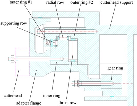
In the process of tunnel construction, the main bearing bears thrust force, radial force and moment, and thrust force is much larger than radial force. The rollers of supporting row don’t carry any thrust force in excavation, only act when cutterhead is drawn back. In this case, the rollers of thrust row have to bear thrust force and moment both, and the corresponding raceways are damaged most likely. Therefore, the load distribution and contact stress are considered in raceway of thrust row only in this paper.
Fig. 1The Main bearing of TBM
There are many factors that have influences on the contact stress of raceway, including magnitude of load, sizes of bearing rings and rollers, machining accuracy and assembly clearance [10, 11]. When geological parameters, sizes and layout of cutters are known, thrust force, radial force and moment carried by the main bearing could be predicted [12, 13]. For the bearing applied misaligned loads, there are two ways to calculate the loading distribution and contact stress of raceway usually. One of them assumes that inner and outer rings are rigid and deformation occurs in rollers only, and calculates the load distribution by taking line contact as point contact, then gets the contact stress based on the elastic contact theory [14, 15]. The other one gets the contact stress iteratively on the basis of theories of Hertz contact and elastic contact by assuming that the elastic approach has linear gradient [16-19]. Both methods above are based on the assumption that all the loads are equivalent and applied in the center of bearing without the characteristics of quadratic moment. To satisfy that assumption, bearing or its support must be rigid, or part of rollers carry more amount of load. However, the main bearing is flexible with large diameter and low spatial compactness, and the thrust force can be at level of kiloton. So the stiffness of support structures must be considered to get the load distribution accurately.
The main structures of TBM cutterhead system are shown as Fig. 2. With the restrictions of weight, space and function, multiple radial stiffeners are placed in cutterhead and cutterhead support to improve the ratio of structure rigidity-to-gravity. The number of stiffeners, restricted to the layout of cutters or drives respectively, is difficult to change.
Fig. 2Structures of cutterhead system
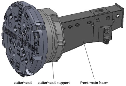
Fig. 3Integral cutterhead with radial stiffeners
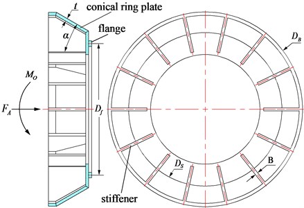
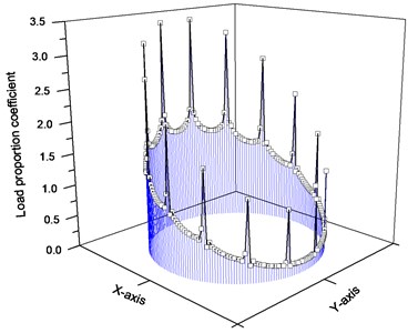
Taking cutterhead for example, all the thrust force and moment transferred through the flange would be applied to the main bearing as boundary conditions. Taking the stiffener thickness as unit length, the intermediate diameter of the flange, approximately equal to the diameter of main bearing, is discretized into nodes and axial constraints are applied. Among them, is the number of stiffeners arranged evenly. Assuming that the front panel of cutterhead is rigid and are loaded. For any , axial force carried by node could be got by FEM-model. With the mean load as a scale, dimensionless , load proportionality coefficient (LPC) of each node in the flange, can be defined as Eq. (3), and the standard deviation of is inversely proportional to the uniformity of load distribution:
Due to the radial stiffeners which have changed the axial symmetry of structure stiffness, the axial load distribution in cutterhead flange, as shown above, is not smooth, and has characteristics of quadratic moment obviously. The maximum axial force is much larger than that of ideal ellipse distribution desired, resulting in the increase of maximum contact stress and failure risk of raceway, and the service life of the main bearing is shortened. To avoid the increase of contact stress caused by axial concentrated load, structures of TBM cutterhead system, as the associated parts of the main bearing, should be properly designed to improve the uniformities of stiffness and load distribution.
Fig. 4Axial LPC in cutterhead flange
2.1. Structure with radial stiffeners of cutterhead
The type of cutterhead is related to its diameter. If the diameter is less than 4 m, the cutterhead is integral most likely, and the diameter ratio of main bearing to cutterhead is relatively big. Thrust force is transmitted by conical ring plate and radial stiffener together. For its diameter is large, about 8 m for example, the cutterhead is separated type to transport easily, and the diameter of main bearing, substantially equal to the intermediate diameter of flange, is much smaller than that of cutterhead.
For the integral cutterhead shown as Fig. 3, load distribution in flange is effected primarily by conical ring plate and stiffeners. The stiffness uniformity would be improved by increasing the stiffness of conical ring plate because of its axial symmetry, and the opposite effect would be achieved if the thickness of stiffener is increased. Considering conical ring plate separately, its stiffness is given as Eq. (4) [20]:
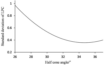
where, is the elastic modulus of the material, is the thickness, is the half-cone angle, and are the big diameter and small diameter of conical ring plate. is equal to the diameter of cutterhead , and is determined according to the front shield and main bearing. Taking both of them as constants, increases with , as will the weight of structure and the overturning moment. Taking the partial derivation of with respect , reaches the maximum when is equal to 35°. The other way to improve the stiffness uniformity is decreasing , as thin as enough if the structural strength is satisfied. In summary, if is appropriate, the best way to improve the uniformity of structure stiffness is changing . For different , LPC in cutterhead flange, as shown in Fig. 4, could be calculated according to ANSYS Parametric Design Language (APDL) and FEM-model, and the standard deviation is changed with too, as shown in Fig. 5. As same as the stiffness of conical ring plate, uniformity of load distribution in cutterhead flange reaches the extremum also when is about 35°.
For the separated type cutterhead shown as Fig. 6, conical ring plate is structurally distant from the flange, and its stiffness has little effect to the load distribution uniformity in the flange. Therefore, it can be considered that the radial stiffeners carry all the thrust force.
Fig. 5Relationship between standard deviation of LPC and half-cone angle
As shown in Fig. 4, the stiffener load consists of two parts. One is the axial force distributed uniformly, and the other is caused by moment, which is proportional to the distance of stiffener projected point in the flange diameter from the moment axis, . Based on the moment balance, elastic deformation and the assumption that front panel of cutterhead is rigid, the forces carried by stiffeners could be got also. Taking the stiffener of carrying maximal axial force as No. 1, its neutral plate is coincided with the symmetry plane, and other stiffeners are clockwise sorted. Considering is an even number and the structural symmetry, the number of stiffeners whose load is needed to be calculated is . Given that load is evenly distributed in stiffener thickness direction, then for any, the amplitude of stiffener’s axial force is obtained by Eq. (5), and is the total moment caused by axial eccentric load, weight of cutterhead and radial force:
Fig. 6Separated type cutterhead with radial stiffeners
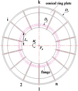
Opposite to the integral cutterhead, increasing stiffener thickness would have positive effect on uniformity of load distribution in the main bearing, because the amplitude of the concentrated load would decrease.
2.2. Adapter flange
As the connector of the cutterhead and inner ring of the main bearing, adapter flange is rotary structure, and its stiffness is axisymmetric. Ignoring the parts of carrying no axial force, the flange could be simplified as a cylindrical with approximately the same intermediate diameter as the main bearing. Although the flange thickness is large, the ratio of it to intermediate diameter is only about 0.05, and the adapter flange could be considered as shell. According to the geometric equations, the equilibrium differential equations and the physical equations on the basis of shell theory, the relationship between structure displacement, internal force and axial load can be revealed.
The adapter flange is continuous and axisymmetric, and its deformation is small because of its high stiffness. Even in extreme condition, its maximum stress is much less than the yield stress. So the adapter flange could be simplified to a linear elastic structure, and it is suitable for superposition principle. Moreover, no matter what type the load distribution in the flange of cutterhead is, it meets Dirichlet principle. Taking it as external load applied in the intermediate diameter of adapter flange, the Fourier series representation of it is shown as follows:
where, is the constant value of force that No. enforcement loaded, is the harmonic amplitude of force that No. enforcement loaded when the frequency of harmonic is , is the intermediate radius of adapter flange, and is the arc length in intermediate diameter.
Using Levy method to solve, the displacement of adapter flange neutral plane is the function of axial direction and ring direction in cylindrical coordinate system, and it can be described as Eq. (7):
where, . Substituting the Eq. (7) into the basic differential equation of shell theory, if it is satisfied, the following equation is required:
where, is bending stiffness, is Poisson’s ratio, and is the wall thickness of adapter flange.
For the size and material of structure, the value of is pretty small. Taking the TBM made by China Railway Construction Corporation (CRCC) as example, it is about 8.066×10⁻¹¹ and can be ignored. According to its characteristic equation, two real number quadruple roots are got, they are, . Based on the boundary conditions of loading and constraints, the general solution of can be obtained. On the basis of superposition principle, the expression of under any axial load can be got. Considering the relationship between displacement and load, the internal axial force can be determined as:
As a result of above, increases with the raising of the harmonic frequency on intermediate diameter of the adapter flange. The axial force transmitted from the adapter flange to the main bearing is constituted by various harmonic loads with those amplitudes attenuated. The amplitudes of various frequencies change with axial length of flange, as shown in Fig. 7.
Higher the frequency is, faster the amplitude attenuates. If the axial length of the adapter flange increases, the amplitude of quadratic moment load would obviously decrease and the uniformity of load distribution in the main bearing would be improved, although the overturning moment would increase by moving of the cutterhead center of gravity.
Fig. 7Harmonic amplitude of internal force in dependence on axial length of flange
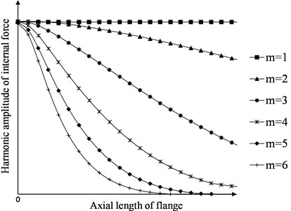
Fig. 8Effect of adapter flange on load distribution
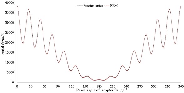
FEM could be introduced to validate the analytical model above. Considering that the result of FEM is dispersed, the integral result of analytical method should be calculated within the length of element. With the same boundary conditions and parameters, results of both methods are shown in Fig. 8. When 140 terms of Fourier series are employed, the analytical result agrees well with the FEM’s. Compared the input step load defined as Eq. (5), the output load distribution is smoother although the characteristic of quadratic moment is still significant.
As axisymmetric component has the effect of filtering the peak of quadratic moment load to improve the load distribution in the main bearing, increasing the length of the cutterhead flange, which is also axisymmetric, would have the same effect as the adapter flange. As the cutterhead support is structural similar to the cutterhead with the radial stiffeners arranged, increasing the axial length of its flange connected to the inner ring of the main bearing would also improve the load distribution in the main bearing, if the structure weigh is allowed.
2.3. Cutterhead support and front main beam
Cutterhead support is also called reduction box. As mentioned previously, the radial stiffeners are arranged. Number of them is associated with the number of driving units, and hardly changed. According to the analysis above, the stiffener thickness would be as thin as possible to increase the uniformity of stiffness with the structural strength satisfied. The outer ring plate, with no taper, is near to the intermediate diameter of main bearing, and increase of its stiffness would improve the uniformity of load distribution in main bearing.
For the open-type TBM, most of front main beams have a hollow rectangular cross-section to get the affiliated equipment installation platform. The stiffness uniformity of cutterhead support is reduced significantly as the section is changed abrupt both in size and shape. Compared with other factors mentioned above, it influences the load distribution most. To improve the situation and extend the service life of main bearing, either increasing the structural bending stiffness or changing the contact surface between front main beam and cutterhead support is needed. For the first option, achieving it needs to increase the plate thickness with the restrictions of drive units mounting dimensions and structure type, and weigh will increase obviously while the bending stiffness increases few. For the second option, cross-sectional form of front main beam should be changed to be circular, so do the corresponded stiffeners in the cutterhead support. Keeping a certain length, its section could be transitioned to a rectangle. The diameter should be as large as possible to close the dimension of main bearing in order to increase the uniformity of load distribution in the roller contact line.
3. FEM-model of cutterhead system structure
To obtain the accurate load distribution on the thrust raceway of main bearing and calculate the service life, three-dimensional (3D) FEM-model of the main structure should be built with load, stiffness characteristic and boundary conditions considered comprehensively. Rated thrust force will be applied in the model to simulate the extreme working condition. According to Newton’s third law, there are two cases of load and constrain for the analysis model. If cutters are constrained and the front beam is loaded, part of them will carry tension because of the cutterhead deformation, and this is obviously inconsistent with the fact. For the other case, if the front main beam is constrained, the rated forces are applied to cutters or cutter seats according to their sizes and types.
Fig. 9Arrangement of S-type weight sensors and aluminum columns: 1-10 – S-type weight sensors, 11 – aluminum columns, 12 – guide columns, 13 – mounting plate
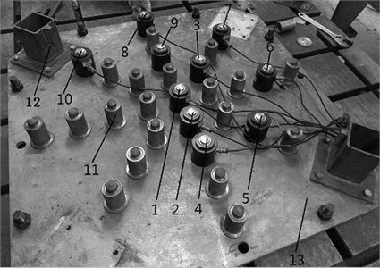
Fig. 10Loading experiment system: 1 – reaction frame, 2 – hydraulic jack, 3 – 20 t weight sensor, 4 – conical structure, 5 – cutterhead, 6 – electric hydraulic pump, 7 – PC
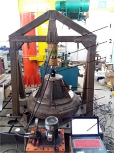
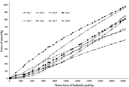
Cutters with same sizes and types carry different loads because the cutterhead is not rigid. To reveal the effect of the cutterhead stiffness on cutters loads, the loading experiment is conducted on the basis of the similitude theory. A cutterhead has been machined based on the TBM manufactured by CRCC, and its diameter is 1m. Taking S-type weigh sensors and aluminum columns with equivalent stiffness as the sensor to simulate the cutters, as shown in Fig. 9, we built the loading system consisting of reaction frame, hydraulic jack, conical structure, cutterhead and workbench shown in Fig. 10. When electric hydraulic pump is working, the piston of hydraulic jack is out and thrust force increases, then forces of sensors are recorded, as shown in Fig. 11. As the thrust force of hydraulic jack is 0, all the sensors carry equal load because of the weight of structures. With the thrust force increases, forces of sensors change with different gradients.
According to the experiment result, taking rated forces as boundary condition will get the imprecise load distribution in main bearing. Forces of cutters are affected by layout of cutters, mounting angle, stiffness of cutterhead and properties of rock. It is the key that how to simulate the relationship between the cutter and rock in the FEM-model. To take these characteristics into account and consider the computational efficiency, springs with nonlinear stiffness are employed on the basis of CSM method [21], to simulate the relationship between cutter and rock. One end of the spring is connected to cutter seat, and the other end is constrained when the front main beam is loaded. The stiffness of the spring can be described as Eq. (10):
where, is the cutter diameter, is the penetration, is cutter pinch, is cutting edge, is the rock uniaxial compressive strength, is the unconfined shear strength. Critical stress of cutter increases with its mounting angle [22], and this influence could be equivalently converted to the change of uniaxial compressive strength, namely, .
Fig. 11Relationship between thrust force of hydraulic jack and forces of sensors
On the basis of the structure and construction geological parameters of CRCC TBM, FEM-model is built, as shown in Fig. 12. To get the contact stress in thrust raceway, contact algorithm is employed to simulate the relationship between roller and raceway. Parameters and assumptions are listed as follow.
Fig. 12Finite element models of TBM main structures
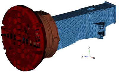
a) Structures of cutterhead system
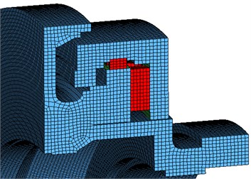
b) Main bearing
(1) The diameter of the cutterhead, , is 7930 mm. There are 47 cutters installed at different radius of the cutterhead, including 4 double-edged center cutters (17 inches), 32 face cutters (19 inches) and 11 gage cutters (19 inches).
(2) The intermediate diameter of the main bearing, , is 4730 mm. the number of rollers, , is 90, and they were arranged in thrust row averagely. The diameter of thrust roller, , is 110 mm, and the length of thrust roller, , is 240 mm. The rollers of supporting row are ignored in the model.
(3) The weights of driving units are relatively small, so they are ignored. However, the impact of those assemble holes on stiffness is considered. The bolt holes, the chamfers and the corners in the structures are deleted to improve the effectiveness of calculation.
(4) is axial only, and the thrust force of TBM is 15330 kN applied to hydro-cylinder hinge point averagely on both sides of the front main beam. The overturning moment is caused by weight of cutterhead only. Surrounding rock is granite and is set to be 160 MPa, is set to be 30 MPa.
4. Load distribution and structure optimization
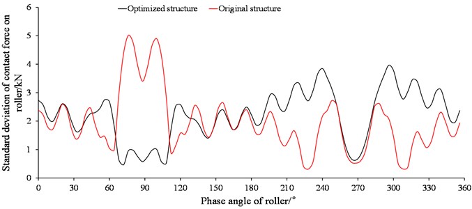
By getting contact stresses in contact line of each roller and then converting them into forces, axial force distribution on thrust row and standard deviation of contact forces on roller can be obtained, and the relationships between them and the phase angle of thrust roller are shown in Fig. 13 and Fig. 14. In a macro perspective, the load is concentrated seriously about 270° in thrust raceway, and this is the result caused by the characteristics of stiffness and boundary condition of the cutterhead support almost. The axial force of roller reaches the peak value where the radial stiffeners arranged. In a micro perspective, the load distribution in contact line of thrust roller is also affected. It fluctuates sharply and edge-effect is taken place most likely where phase angle is about 90° or 270°.
According to the analysis above, load distribution in the main bearing changes with the structure parameters, such as half cone angle of conical ring plate in cutterhead, stiffener number and thickness, adapter flange length and cross-sectional form of front main beam. On the basis of that, cutterhead system structure can be optimized to improve the service life of main bearing with some structural limitations.
(1) The half cone angle of conical ring plate is changed to be 35° to increase its stiffness although the cutterhead is separated type.
(2) The number of stiffeners is limited by the layout of cutters, and the thickness is increased by 20mm with the structure size and function considered.
(3) The flange length of cutterhead support is increased by 60 mm, and the total mass is about 70 tons which is limited by transport conditions.
(4) The cross-sectional form of front main beam is changed to be circular, so do the corresponded ribs in the cutterhead support. The diameter of the section is 3320 mm which is as large as possible and has non-interference with the drive units.
Fig. 13Axial force distribution on thrust row raceway
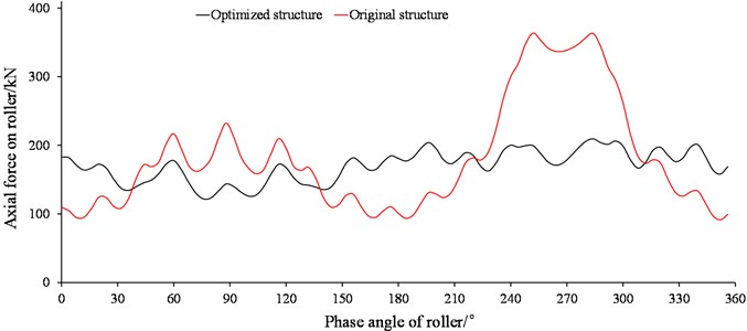
Compared with the original, load distribution on thrust row raceway is much smoother, and it still fluctuates slightly in the positions of stiffeners arranged which means the flange length of cutterhead support should increase more if weight allows. The standard deviation of axial force distribution on thrust raceway decreases by 71.5 %. The key reason for that is the structure changes both in the front main beam and cutterhead support. For the contact lines of rollers, the maximum of contact force standard deviation decreases, so do the maximum contact stress in raceway by 31 %. It is very helpful to extend the service life of main bearing.
Fig. 14Standard deviation of contact forces on roller of thrust row
5. Life calculation of main bearing
There are three common methods used to calculate the life of the main bearing, L-P, ISO, and I-H. All of them are based on the L-P theory with mainly differences in the basic rated dynamic load , equivalent load and constant . Both L-P and ISO method reflect uneven load distributions in raceway and contact line with correction coefficients. If bearing support is stable and uniform, they are efficient in calculation. For the main bearing with uneven load distributions in raceway and contact line both, I-H method would be more appropriate because the results are obtained by taking their effects in account. In I-H method, contact line of roller is divided into several pieces, and the basic rated dynamic load on each one is defined as follow:
where, is the basic rated dynamic load, is the diameter of roller, is the diameter of raceway, is the length of roller, is the number of pieces, and is the number of rollers.
For each piece, is equivalent with the contact force which could be obtained in the result of FEM-model. Assuming that fatigue damage occurs only in the thrust raceway, life of the main bearing (106 revolutions) is determined as Eq. (12) in I-H method:
where, and are constant. For line contact, is 4 and is 9/8.
According Eq. (11) and Eq. (12), for different thrust forces, service life of the main bearing is changed with the equivalent load. The influence of thrust force on life of the main bearing for rectangular front main beam is shows as Fig. 15.
Fig. 15Relationship between TBM thrust force and TBM main bearing life
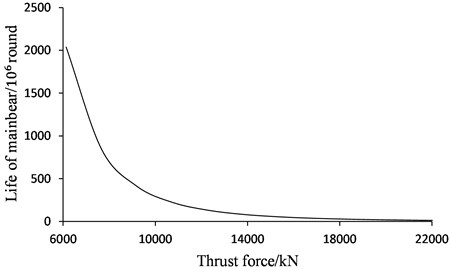
Record the thrust force when TBM is working, and number of the payload is . Divide the maximum thrust force into intervals, and statistics are carried on payloads to obtain the frequency in each interval. Then life can be calculated respectively if considering that the recorded thrust forces are replaced with the median of the interval. According to Eq. (11), Eq. (12), thrust force distribution and the relationship between median of force interval and life of the main bearing, life could be calculated based on Eq. (12).
Fig. 16Thrust force distribution recorded in 10 days
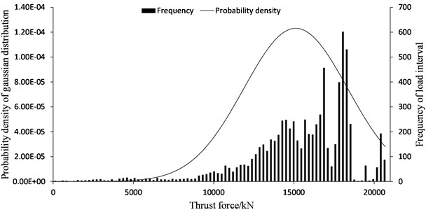
For CRCC TBM, thrust force distribution recorded in 10 days is shown in Fig. 16, and life of the main bearing is about 16867 hours when transfer efficiency is considered to be 0.9. Compared to the desired life, 15000 hours, it is just satisfied and has a little stall margin. Once the rock is harder and thrust force increases, fatigue damage may happen in raceway. For the optimized structure, the contact stress of raceway decreases a lot, and the service life of the main bearing is extended to 24744 hours which is 46.7 % higher than the original.
6. Conclusions
Structure stiffness of TBM cutterhead system has great influence on uniformity of load distribution in the main bearing. The structural mutations of size and shape decrease the axial symmetry of stiffness at the load path, then load concentrate inside bearing. By adjusting the half cone angle, the number and thickness of stiffener, the length of adapter flange, and the cross-sectional form of front main beam and corresponded ribs of cutterhead support, uniformity of load distribution in main bearing can be improved, contact stress of raceway will decrease and the service life of the main bearing will be extended.
A 3D FEM-model of the main structure is present in order to obtain the accurate load distribution on the thrust raceway of the main bearing. For better consistent with the actual situation, springs with nonlinear stiffness are employed to simulate the rock-cutters relationship on the basis of CSM method. Load distributions and standard deviations in macro and micro perspectives are considered as standards to evaluate the uniformity of structure stiffness.
The structure is optimized based on the influence of stiffness on load distribution. Compared to the original, it increases the uniformity of load distribution by 71.5 % and decreases the maximum contact stress by 31 %, and the service life of main bearing is extended by 46.7 %.
References
-
Han Meidong, Cai Zongxi, Qu Chuanyong, Chen Kui Tunneling Simulation and Strength Analysis of Cutterhead System of TBM. Intelligent Robotics and Applications. Springer International Publishing, 2015, p. 445-455.
-
Xia Yimin, Luo Dezhi, Zhou Xiwen Study on the law of geology adaptability cutter selection for shield. Journal of China Coal Society, Vol. 36, Issue 7, 2011, p. 1232-1236.
-
Hassanpour J., Rostami J., Zhao J. A new hard rock TBM performance prediction model for project planning. Tunnelling and Underground Space Technology, Vol. 26, Issue 5, 2011, p. 595-603.
-
Wang Yanbo Failure types of main bearing of TBM and analysis on faults of main bearing of TBM applied in construction of West Qinling Tunnel. Tunnel Construction, Vol. 34, Issue 10, 2014, p. 1011-1018, (in Chinese).
-
Tang Yu, Wu Qingshan, Han Zhiyuan Main bearing replacement and treatment in tunnel processing. Modern Tunnelling Technology, Vol. 46, Issue 1, 2009, p. 64-70, (in Chinese).
-
Du Yanliang, Xu Mingxin, Zhi Xiaohui Full Face Hard Rock Tunnel Boring Machine-Monitoring and Maintenance. Huazhong University of Science and Technology Press, Wuhan, 2011, (in Chinese).
-
Lundberg G., Palmgren A. Dynamic capacity of rolling bearings. Journal of Applied Mechanics – Transactions of the ASME, Vol. 16, Issue 2, 1949, p. 165-172.
-
Palmgren A. Ball and Roller Bearing Engineering. Third Edition, SKF Industries Inc., Philadelphia, 1959.
-
Coe Harold H., Zaretsky Erwin V. Effect of interference fits on roller bearing fatigue life. Tribology Transactions, Vol. 30, Issue 2, 1987, p. 131-140.
-
Göncz P., Potofinik R., Glodež S. Load capacity of a three-row roller slewing bearing raceway. Procedia Engineering, Vol. 10, 2011, p. 1196-1201.
-
Göncz P., Drobne M., Glodež S. Computational model for determination of dynamic load capacity of large three-row roller slewing bearings. Engineering Failure Analysis, Vol. 32, 2013, p. 44-53.
-
Zhang Zhaohuang, Zhou Jilei, Liu Ruihua Force analysis of TBM Main Bearing. Journal of Basic Science and Engineering, Vol. 1, Issue 2010, 2010, p. 225-232, (in Chinese).
-
Ramoni M., Anagnostou G. Thrust force requirements for TBMs in squeezing ground. Tunnelling and Underground Space Technology, Vol. 25, Issue 4, 2010, p. 433-455.
-
Wei Wenming, Lü Dun, Zhang Jun, Zhao Wanhua Static stiffness of three-row cylindrical roller bearing for rotary table. Journal of Xi’an Jiaotong University, Vol. 48, Issue 12, 2014, p. 8-14, (in Chinese).
-
Deng Sier, Jia Qunyi, Xue Jinxue Ball Rolling Design Principles. Second Edition, Standards Press of China, Beijing, 2014, (in Chinese).
-
Heydari M., Gohar R. The influence of axial profile on pressure distribution in radially loaded rollers. Journal of Mechanical Engineering Science, Vol. 21, Issue 6, 1979, p. 381-388.
-
Fujiwara H., Kawase T. Logarithmic profiles of rollers in roller bearings and optimization of the profiles. NTN Technical Review, Vol. 75, 2007, p. 140-148.
-
Wang W.-Z., Wang H., Liu Y.-C., Hu Y.-Z., Zhu D. A comparative study of the methods for calculation of surface elastic deformation. Proceedings of the Institution of Mechanical Engineers, Part J: Journal of Engineering Tribology, Vol. 217, Issue 2, 2003, p. 145-154.
-
Horng T. L. Analyses of stress components for a circular crowned roller compressed between two flat plates. Proceedings of the Institution of Mechanical Engineers, Part J: Journal of Engineering Tribology, Vol. 221, Issue 5, 2007, p. 581-589.
-
Lian Yongzheng, Wang Mingyu, Pan Zhongwen Axial stiffness of conical shell structures. Missiles and Space Vehicles, Vol. 5, 2011, p. 47-49, (in Chinese).
-
Rostami J., Ozdemir L., Nilson B. Comparison between CSM and NTH hard rock TBM performance prediction models. Proceedings of Annual Technical Meeting of the Institute of Shaft Drilling Technology, Las Vegas, 1996, p. 1-10.
-
Xia Yimin, Wu Yuan, Guo Jincheng, Tian Yanchao, Lin Laikuang Numerical simulation of rock-breaking mechanism by gage disc cutter of TBM. Journal of China Coal Society, Vol. 39, Issue 1, 2014, p. 172-178, (in Chinese).
Cited by
About this article
This work is supported by Grant 2013CB035402 of the National Basic Research Program of China and 51275070 of the National Natural Science Foundation of China.
Chunguang Zhang contributed to analysis and manuscript preparation. Fuzheng Qu contributed to the conception of the study. Li Guo helped the translation and language polishing. Junzhou Huo helped the analysis with constructive discussions. Zhengyi Xie performed the experiments and relative devices.
