Abstract
This paper investigates the usage of functionally graded beam as a bracing member in building-type structures subjected to severe ground motions. Material distribution of functionally graded beam follows power law form along thickness direction. Equivalent stiffness of functionally graded brace (FGBr) is derived and confirmed analytically through applying strain energy equilibrium and appropriate boundary conditions on Euler-Bernoulli beam element for simulation of brace behavior. The seismic response analyses of single and multi-storey shear-type buildings with FGBrs are performed on lumped mass-stiffness models. This modeling technique is validated in terms of fundamental natural periods by continuous and numerical solutions. The effect of varied Young’s modulus and power law exponent on maximum responses such as displacement, storey drift and base shear is evaluated under both harmonic and severe earthquake motions.
1. Introduction
Concentrically braced frames for the aim of resisting lateral loads have a wide application area in civil engineering field because of its simplicity in implementation to both existing and new structures and efficiency in enhancing seismic behavior of structures. Braces are usually steel or composite structural elements that help to resist seismic loads by means of their axial stiffness. There are many concentrically braced frame configuration types such as diagonal, chevron, X-braced, zipper frames while the behavior of each is similar [1]. Considerable amount of numerical and experimental studies on braced frame structures are available in related literature. Mass irregularity in multi-storey buildings with concentrically braced steel frames was investigated by Tremblay et al. [2]. MacRae et al. presented flexural stiffness effect of columns of braced frame during seismic motion [3]. Tremblay et al. presented the results of an experimental study on rectangular hollow steel bracing members in diagonal and X-bracing configuration form to examine buckling and yielding behavior [4]. Youssef et al. recommended using steel concentric X-braces for reinforced concrete moment resisting frames under lateral loads as a result of an experimental study [5]. Concentrically braced steel frames with shape memory alloys were evaluated in the study of McCormick et al. They obtained enhanced ductility and energy dissipation behavior in short and mid-height multi-storey buildings [6].
The lumped mass-stiffness model which is a satisfying model for shear-type buildings is widely used for building-type structures whose lateral deformation is important under lateral loads such as wind, earthquake etc. [7-10]. The masses are concentrated at the floor levels because of concentration of major amount of total mass in rigid floors. Lateral loads are resisted by lateral stiffness provided only by columns assumed as massless springs. Midorikawa et al. considered six-storey K-braced building as simple lumped mass shear-type six mass system in design-level analysis [11]. Hiemenz et al. showed the effective usage of MR braces in buildings to mitigate seismic responses. They perform experimental and analytical analyses on lumped parameter system of single- and three-storey buildings [12]. Hajirasouliha et al. carried out seismic analyses on concentrically braced multi-storey buildings by using conventional and modified shear building models that they developed [13]. The results show that conventional shear-building model is capable of estimating fundamental natural frequency and maximum displacements of storeys.
In recent years, with the improvement in material science, functionally graded materials (FGMs) have been developed as an alternative to composite materials. This new material is superior to composites in terms of distribution of stress continuously because of smooth variation of material properties. In this sense, researchers pay considerable attention for usage of FGM members in engineering fields such as aerospace, automotive, mechanics etc. Application of FGM, mostly in dynamical systems, brings out the necessity of understanding its vibration characteristics in the first step. Therefore, there are vast of work in literature including determination of the vibration characteristics of FGM element with various approaches [14-18]. As a promising research presented in this study, two separate research subject is combined by implementation of FGM brace to building-type structures in order to investigate their behavior under earthquake motion. In the literature, to the best knowledge of the author of this article, a published study which can be comparable with this study including seismic behavior of FGM braced frame does not exist. Therefore, this paper focuses on a parametric study presenting the effect of Young’s modulus variation of material constituents and power law exponents on seismic time responses due to severe earthquake motions.
In this paper, single and multi-degree of freedom shear-type buildings with functionally graded braces (FGBr) attached are investigated through harmonic and earthquake loads. Diagonal braced frame configuration is used since the diagonal bracing provides equal resistance to lateral loads in tension and compression supplying balance in dynamic behavior [19]. The material distribution of FGBr along the thickness direction follows power law form. At first, an equivalent stiffness of FGBr is derived analytically applying appropriate boundary conditions on Euler-Bernoulli beam element to simulate the behavior of a diagonal brace placed across the corners of frame structure. The structural models of buildings are constituted by lumped mass-stiffness models which are validated by continuous and numerical solutions in terms of fundamental natural period. Equation of motion with supplemental terms of braces is solved by performing one of numerical integration methods, i.e., Newmark- integration method, to obtain time responses of braced buildings. The effect of power law exponent on single-storey building behavior under harmonic load is shown through amplification factor and acceleration responses versus the frequency ratio between natural frequency of the structure and excitation frequency. In addition to that, seismic behavior of both single- and multi-storey buildings is analyzed under strong ground motions selected. The behavior of buildings is investigated parametrically by changing the parameters such as power law exponent and Young’s modulus ratios of FGBr in addition to severity of earthquake motions.
2. Formulations
2.1. Assumptions
This study focuses on the dynamic behavior of frame structures with diagonally placed FGBrs and investigates the effects of FGBr parameters on structural dynamic behavior in two-dimensional plane. In order to achieve this aim, there are some assumptions which are noted in this subsection. The buildings are modeled as shear-type structures in which floors rigidly moves only in horizontal direction due to seismic forces without any lateral deformation. Masses are concentrated at the floor levels and lateral stiffness is provided by columns and braces. Equation of motion is governed by lumped mass-stiffness model in which only horizontal motion is important. Since the effect of energy dissipation of brace due to nonlinear cyclic response is neglected, diagonal FGBr displaces only in axial direction in fully elastic manner without yielding in tension and buckling under compression. Euler-Bernoulli beam theory is valid to derive equivalent stiffness of FGBr. Under these assumptions, the emphasis will be given on dynamic responses of shear-type buildings with regard to varied FGBr parameters.
2.2. Functionally graded beam
In recent years, functionally graded materials (FGMs) have been developed as an alternative to composite materials. The material properties are altered gradually through a defined function in the cross-section. Consider a uniform FG beam (FGB) with rectangular cross section, with width and thickness , following material distribution in power-law form along thickness direction. Longitudinal and transverse axes of the beam are along and coordinates, respectively. In this case, material properties for FGB become function of coordinate as in the following equation:
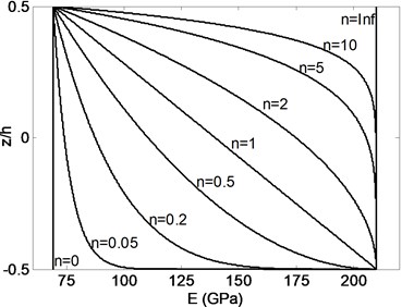
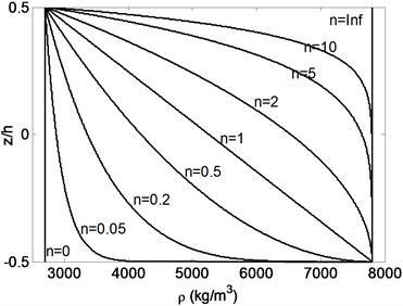
where and are the upper and lower material properties, respectively, whereas is power law exponent defining the material variation profile. For a FGB which has material distribution of steel and aluminum grading from bottom to top, Fig. 1 shows the variation of Young’s modulus and mass density for different power law exponent values along the thickness direction of a beam. The beam is pure aluminum for , and pure steel for .
Table 1Material properties of FGB constituents
Material | Young’s modulus (GPa) | Mass density (kg/m3) |
Aluminum | 69 | 2700 |
Steel | 210 | 7800 |
Fig. 1Variation of Young’s modulus and mass density through the thickness of FGB for varied power law exponents
2.3. Equivalent stiffness and lumped mass parameters of FGBr
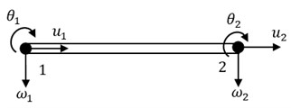
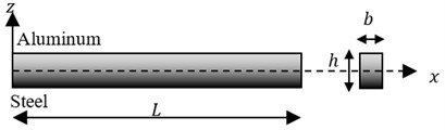
In this section, equivalent stiffness and mass of FGBr are found out to perform dynamic response analyses of braced structure. Beam model in Fig. 2(a) is constituted to define boundary conditions. Consider a uniform FGB with rectangular cross-section in -plane composed of steel and aluminum following power law form along thickness direction as shown in Fig. 2(b). Based on Euler-Bernoulli beam theory, longitudinal displacement , which is the function of axial spatial variation and time , is given by:
where and are longitudinal and transverse displacement components at any point on the neutral axis while denotes transverse spatial variation. In this study FGBr is assumed to displace only along longitudinal axis to simulate the brace behavior in the frame. Therefore, only longitudinal displacement component is taken into account by neglecting transverse component caused by beam deflection (moment effect). The boundary conditions for FGBr can be written as , at and , at . Then the element formulation of FGBr becomes as follows [14]:
where and are the first-degree polynomial interpolation functions. denotes length.
Fig. 2a) Beam model and b) grading configuration of FGBr
a)
b)
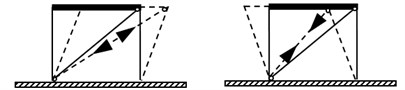
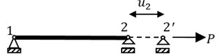
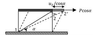
In the frame system, FGBr is placed diagonally across the column-beam joints with the both ends pinned and behaves as shown in Fig. 3(a) during lateral loads forcing to lengthen and shorten. This behavior is modeled by simply supported beam under a horizontal load as given in Fig. 3(b). Fig. 3(c) shows that if FGBr is placed diagonally with an inclination angle , the frame displaces in the lateral direction.
Fig. 3a) FGBr behavior under tension and compression in the frame, b) model of FGBr under axial loading, c) displaced braced frame
a)
b)
c)
The equivalent stiffness of brace is derived from the general definition of the axial stiffness, that is, the force that produces unit displacement in the longitudinal direction. For a FGB, since Young’s modulus is function of coordinate , axial stress also becomes function of given as:
where denotes axial strain which is computed as from Eq. (3) by differentiation of unit displacement with respect to . The relation between applied force and deflection is calculated by the integration of the product of and width along the height of the beam as follows:
Accordingly, substitution of into Eq. (5) gives equivalent stiffness of FGBr as follows:
where is taken as:
From axial strain energy equilibrium of continuous and equivalent stiffness solution, equivalent stiffness formulation can be validated as:
where and denote infinitesimal and largest deformation along axial direction. Displacement function is determined as . By taking the derivative of this function with respect to , is obtained. As a result, equivalent stiffness computed by Eq. (8) is found identical to Eq. (6). For diagonal placement of FGBr, the longitudinal force , acting along simply-supported brace model, becomes in the lateral direction. As a conclusion, equivalent stiffness for diagonally placed FGBr becomes .
The mass of structural elements can be concentrated at the storey levels in shear-type buildings [7-13, 21]. In this paper, since the FGBrs are attached to the floors, its mass is concentrated at the joint where the displacement occurs, i.e. floor levels, as given in Eq. (9):
where is mass density.
2.4. Lumped mass-stiffness structural model
Under dynamic loads such as earthquakes, the governing equation of motion of lumped mass-stiffness structure is written as:
where is mass, is damping coefficient, is stiffness matrices and , , are displacement, velocity and acceleration response vectors found at each time step. The over-dot denotes the derivative with respect to time and is influence coefficient on the form of a unit vector . Besides, denotes real acceleration data of an earthquake. Under harmonic motion, the right hand side of equation becomes in which and is the amplitude and frequency of harmonic load, respectively. As excitation load, both harmonic load and real earthquake acceleration of severe earthquake motions are used to compute structural responses of braced systems.
Mass () and stiffness () matrices of the brace should be assembled into those of the structure. The equation of motion of structure with braces is rewritten as follows:
The constitution of matrices for -storey building is given in detail below:
3. Results
In this section, results of parametric analyses conducted on FG braced building-type structures are presented.
3.1. Validation of lumped mass-stiffness structural model
Very common approach in dynamical analysis of structural systems is to model shear-type buildings by lumped mass-stiffness technique [7-13, 21]. The natural period results of studies in literature are used to validate the lumped mass-stiffness technique used in this paper. Li et al. investigated the natural vibration characteristics of the 5-storey residence building of Beijing New Material Corporation and 27-storey Guangzhou Hotel building by the assumption of cantilever shear beam with distributed mass and stiffness [22]. Medhekar et al. evaluated seismic response of two-storey concentrically braced steel frame of typical office building through numerical analysis conducted by a commercial software package [7]. The building is 8.1 m height and 9 m bay width. Steel sections used for outer columns, floor beam, roof beam and inner column at the first floor are W410×67, W410×60, W530×82 and W200×42, respectively. Also tension-only braces are determined as square HSS102×6 at the first storey and HSS64×4 at the second storey. The lumped parameters of three buildings are given in Table 2. Natural periods of measured, continuous, numerical and lumped mass-stiffness models of multi-storey buildings are compared with each other in Table 3. The results show that the lumped mass-stiffness technique provides acceptable estimation for the fundamental natural vibration characteristics.
3.2. Equivalent stiffness of FGBr
To constitute structural matrices and perform time response analysis of lumped mass-stiffness model of structures, equivalent stiffness of FGBr is required. FGBr taken into account is 7.21 m in length when placed diagonally to a storey with 4 m in height and 6 m in bay width. The square cross-section of FGBr is taken as 25×25 mm2.
Table 2Parameters of buildings
27-storey Guangzhou hotel [22] | ||
Section (height (m)) | Mass (kg) | Stiffness (N/m) |
1 (0-5.35) | 1.87×10⁵ | 5.80×10⁸ |
2 (5.35-15.25) | 4.10×10⁵ | 5.59×10⁸ |
3 (15.25-21.25) | 3.80×10⁵ | 5.62×10⁸ |
4 (21.25-33.85) | 3.66×10⁵ | 5.62×10⁸ |
5 (33.85-43.15) | 3.55×10⁵ | 5.62×10⁸ |
6 (43.15-52.45) | 3.58×10⁵ | 5.59×10⁸ |
7 (52.45-61.75) | 3.02×10⁵ | 5.65×10⁸ |
8 (61.75-76.00) | 5.37×10⁵ | 5.40×10⁸ |
5-storey Beijing New Material Corporation [22] | ||
Storey | Mass (kg) | Stiffness (N/m) |
1 | 25.32×10³ | 1.68×10⁸ |
2 | 25.87×10³ | 1.63×10⁸ |
3 | 23.67×10³ | 1.63×10⁸ |
4 | 25.32×10³ | 1.63×10⁸ |
5 | 25.87×10³ | 1.63×10⁸ |
2-storey concentrically braced steel frame (CBF) [7] | ||
Storey | Mass (kg) | Stiffness (N/m) |
1 | 1.30×10⁶ | 6.05×10⁷ |
2 | 4.15×10⁵ | 3.85×10⁷ |
Table 3Natural periods for multi-storey buildings
Buildings | Natural fundamental period (s) | |||
Measured (Li et al. [22]) | Continuous (Li et al. [22]) | Computed by commercial software (Medhekar et al. [7]) | Present study | |
Beijing New Material Corp. | 0.305 | 0.279 | – | 0.273 |
Guangzhou Hotel | 0.970 | 0.916 | – | 0.895 |
CBF | – | – | 1.120 | 1.122 |
Table 4 shows equivalent stiffness values () normalized by stiffness of pure steel brace for varied Young’s modulus ratios. Young’s modulus ratio denoted by is the ratio between Young’s modulus of upper and lower surface ( of FGBr. In calculations, the mass density ratio of the top and bottom material is taken as unity (. Since and means the brace is pure steel, equivalent stiffness ratio becomes constant as expected. Depending on the value of higher or lower than unity, plays different role on the stiffness characteristics. For gradations when is lower than unity, FGBr approaches to pure steel with increase and to other material with decrease in power law exponent, on the other hand, completely contrary behavior is observed when is larger than unity. This situation arises from material variation form.
Table 4Normalized equivalent stiffness (kb) of FGBr along thickness direction
0 | 0.05 | 0.2 | 0.5 | 1 | 2 | 5 | 10 | ||
0.25 | 0.25 | 0.29 | 0.38 | 0.50 | 0.63 | 0.75 | 0.88 | 0.93 | 1.00 |
0.5 | 0.50 | 0.52 | 0.58 | 0.67 | 0.75 | 0.83 | 0.92 | 0.95 | 1.00 |
0.75 | 0.75 | 0.76 | 0.79 | 0.83 | 0.88 | 0.92 | 0.96 | 0.98 | 1.00 |
1 | 1.00 | 1.00 | 1.00 | 1.00 | 1.00 | 1.00 | 1.00 | 1.00 | 1.00 |
2 | 2.00 | 1.95 | 1.18 | 1.67 | 1.50 | 1.33 | 1.17 | 1.09 | 1.00 |
10 | 10.00 | 9.57 | 8.50 | 7.00 | 5.50 | 4.00 | 2.50 | 1.82 | 1.00 |
50 | 50.00 | 47.67 | 41.83 | 33.67 | 25.50 | 17.33 | 9.17 | 5.45 | 1.00 |
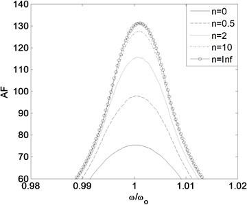
3.3. Effect of power law exponent to responses due to harmonic force
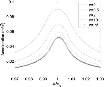
First analyses are conducted on single storey building with FGBr subjected to harmonic forces in order to investigate the effect of different excitation frequencies on dynamic responses. The single-storey building has lumped mass of 5×10⁴ kg, stiffness of 5×10⁴ N/m and damping ratio of 5 %. FGBr is composed of steel and aluminum. The ratio of maximum dynamic response to static response , i.e. amplification factor (AF), is obtained for different power law exponents to clarify the dynamic behavior of the structure in terms of natural angular frequency ratio which presents proportion between frequency of excitation and structure As a general consequence, amplification factor tends to increase when the natural frequency of load and structure come closer implying resonance. Fig. 4(a) confirms that the largest value of amplification factor occurs when frequency ratio is unity regardless of the value of power law exponent. As to clarify the results together with the above section (Table 4), one can say that smaller power law exponent gives smaller equivalent stiffness for the case considered and vice versa can be true if the material formation along the beam is exchanged. In accordance with that, both dynamic displacement and static displacement increase and approach to each other leading to lower amplification factor with decrease in stiffness ensued by lower power law exponent.
The acceleration responses of building-type structures are also significant data for civil engineers and designers. During the low-magnitude earthquakes, even if it is not harmful to structural system, large acceleration during vibration may be disturbing and harmful to people and sensitive devices inside the structure. Besides, large acceleration causes larger base shear. Fig. 4(b) reveals that for resonance frequency, acceleration responses are the largest and in addition, larger results in lower acceleration response with increase in stiffness.
Fig. 4Relation between frequency ratio and a) amplification factor, b) acceleration response under harmonic force
a)
b)
3.4. Seismic responses of FG braced frame
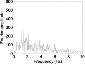
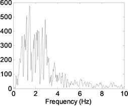
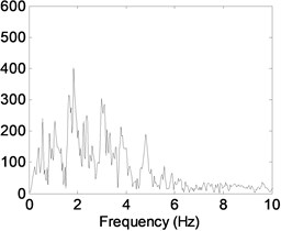
Severe earthquake induced responses are evaluated in this section parametrically. Acceleration data of north-south component of 1999 Duzce, 1995 Kobe and 1940 El Centro earthquakes are used to perform seismic response analysis of single-storey and multi-storey buildings. The acceleration data of earthquakes were downloaded from PEER strong ground motion database (http://ngawest2.berkeley.edu). The reason to select these ground motions is to take into account earthquakes representing different frequency and energy contents. Table 5 tabulates properties of the ground motions selected. The low and high ratio of PGA (peak ground acceleration) to PGV (peak ground velocity) reveals that the earthquake has long- and short-duration acceleration responses, respectively [20]. Predominant frequency for each earthquake has been obtained from Fourier spectra of acceleration time histories as shown in Fig. 5. With this frequency information of earthquakes, seismic behavior of buildings around resonance frequencies will be focused during analyses. Effects of varied power law exponent and Young’s modulus ratios on responses are investigated under these selected ground motions.
Table 5Properties of selected ground motions
Earthquake | Station | PGA (gal) | PGV (cm/s) | PGA/PGV (1/s) | Predominant frequency (Hz) |
El Centro Earthquake (NS), 1940 | Imperial Valley Irrigation District | 341.7 | 33.4 | 10.2 | 1.484 |
Kobe earthquake (NS), 1995 | JMA Kobe | 817.8 | 90.2 | 9.0 | 1.450 |
Düzce earthquake (NS), 1999 | Bolu | 739.5 | 58.3 | 12.7 | 1.851 |
Fig. 5Fourier amplitude spectrum of a) El Centro, b) Kobe and c) Düzce earthquakes
a)
b)
c)
3.4.1. Seismic responses when FGBr is composed of aluminum at the top and steel at the bottom
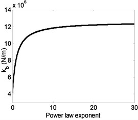
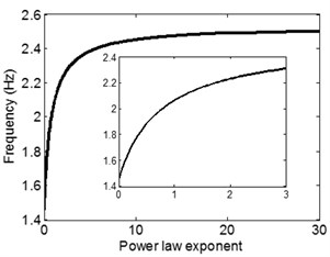
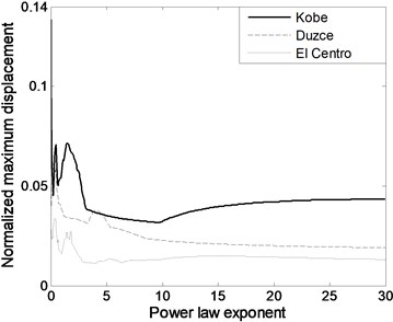
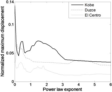
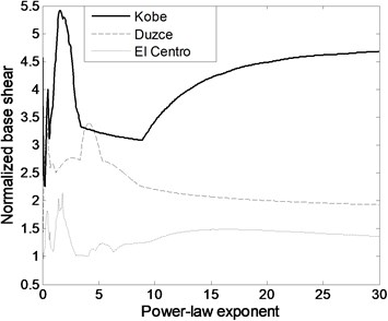
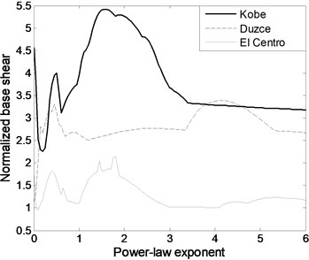
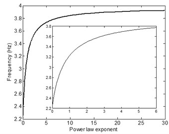
The equivalent stiffness of FGBr and natural frequency of single-storey structure has increasing trend with greater values as seen in Fig. 6(a) and (b). Both equivalent stiffness and frequency parameters increase with decaying slope and approach to those of pure steel member. Fig. 6(b) is used to detect power law exponent value which generates resonance frequency of the structure with FGBrs. Fig. 7(a) shows seismic behavior of structure under selected three earthquake motions in terms of maximum displacement response normalized by the height of the structure. Fig. 7(b) shows zoomed view of Fig. 7(a). Under Kobe earthquake which has intense long-duration acceleration pulses, the structure experiences largest responses among others. Under Kobe and El Centro earthquakes since the predominant frequencies of 1.450 Hz and 1.484 Hz coincide with structural frequency when is around zero, normalized maximum responses occurs at . Furthermore, the variation of maximum displacements with power law exponent represents similar characteristics for both earthquakes. Note also that in Fig. 7(a), displacement responses increases when n is larger than 10 under Kobe earthquake. This is caused by the structural frequency of about 2.5 Hz within the wide predominant frequency range of Kobe earthquake. Under Duzce earthquake, which has predominant frequency of 1.851 Hz, since resonance frequency is attained when is 0.45, maximum displacement response occurs around this frequency as expected and keep decreasing as increases. It is clear that under all earthquake loads, displacement responses are very sensitive to FGBr parameters. Fig. 8 displays base shear forces normalized by total weight of the structure for ascending power law exponent. Base shear forces have similar trend with displacement responses, however, reaction to change in is more visible.
3.4.2. Seismic responses for varied Young’s modulus
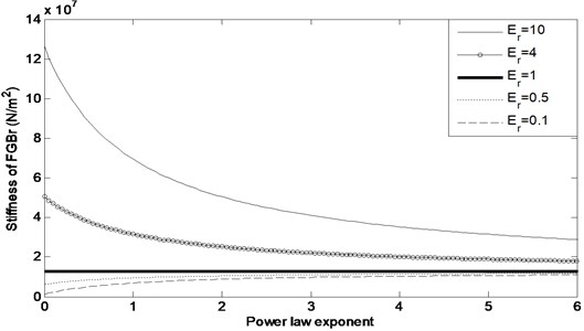
Seismic response analyses of FG braced single-storey building under 1995 Kobe earthquake are also performed in this section for various material constituents of FGBr. The equivalent stiffness for different values is given for varied power law exponents in Fig. 9. According to Young’s modulus of graded materials, equivalent stiffness alters in different characteristics by the change of . When is lower than unity, equivalent stiffness tends to increase and, in contrast with it, when is larger than unity, it tends to decrease gradually with increase in . Nevertheless, for a constant power law exponent value, equivalent stiffness becomes greater for larger . For example, when 2, equivalent stiffness becomes 5.04×10⁷ N/m and 8.82×10⁶ N/m for is 10 and 0.1, respectively. It is clear from the figure that, in all cases, equivalent stiffness of FGBr approaches to the equivalent stiffness of homogenous beam as increases.
Fig. 6Variation of a) equivalent stiffness and b) structural frequency with power law exponent
a)
b)
Fig. 7Variation of a) normalized maximum displacement under selected ground motions and b) its zoomed view
a)
b)
Fig. 8Variation of a) normalized base shear under selected ground motions and b) its zoomed view
a)
b)
Fig. 9Equivalent stiffness for different material constituents
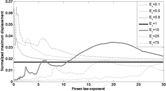
Displacement response analysis of single-storey building is conducted for several values to generalize interpretation of the responses and provide insight into the dynamic behavior. Displacement responses depicted in Fig. 10 are inclined to decrease for small power law index values (between 0 and 4) as rises. When is lower than unity, displacement response has decreasing trend with ascending . In contrast with this situation, when is greater than unity, displacement response has increasing trend with ascending .
Fig. 10Normalized displacement response for different material constituents
3.4.3. Seismic responses in six-storey building
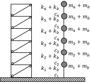
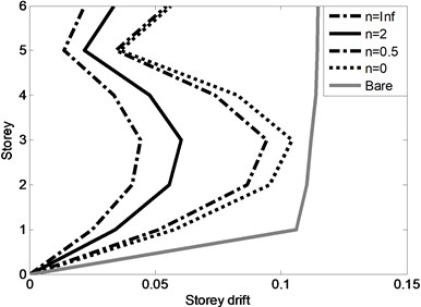
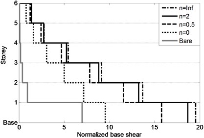
In addition to single-storey building, a mid-rise building (assumed to be six-storey) is also investigated to observe the effect of FGBr parameters on seismic responses under 1995 Kobe earthquake. The building is idealized as lumped mass-stiffness model as displayed in Fig. 11(a) to investigate seismic responses of each storey and entire building in terms of storey drifts and base shear. The bare structure has mass of each storey 7500 kg, stiffness 5×10⁴ N/mand inherent damping ratio 5 %. Rayleigh damping matrix which is proportional to mass and stiffness matrices is used to constitute damping coefficient matrix. Maximum storey drifts and base shear force are normalized by total height and total weight of the building, respectively. It should be noted that predominant frequency of the earthquake does not coincide with dominant frequency (1st mode) of the building with FGBrs for any power law exponent value. Fig. 11(b) shows change in first natural frequency of building by the power law exponent. Fig. 12(a) demonstrates maximum storey drifts for various values. Bare structure which has no braces shows excessive drift of 0.11 at the first storey resulting in soft storey formation. It is clear from the figure that braces are very efficient in terms of reducing displacement responses of the building. Pure steel brace provides minimum storey drifts, especially on the first floor reducing to 0.02, among other graded braces and prevents soft storey formation very efficiently. On the other hand, Fig. 12(b) represents that minimum base shear occurs as a result of less stiffened structure when the braces are pure aluminum. As stiffness increases, base shear response increases.
Fig. 11a) Six-storey building with FGBrs and idealized lumped mass-stiffness model and b) fundamental frequency change of building for varied power law exponent
a)
b)
Fig. 12a) Maximum storey drifts and b) normalized base shear forces for various power law exponents
a)
b)
4. Conclusions
This paper presents a promising study for adoption of new and innovative materials in concentrically braced frames for the aim of upgrading traditional systems. Usage of functionally graded brace (FGBr) as a structural member in building-type structures is assessed in this study. Equivalent stiffness of FGBrs are derived by constituting a beam model with appropriate boundary conditions simulating brace behavior in structural frame. Dynamic behavior of buildings with braces simulated by lumped mass-stiffness model is obtained under harmonic load and severe earthquake motions. The effect of FGBr parameters such as power law exponent and Young’s modulus ratio on seismic responses is also investigated. Since braces change the modal characteristics of structures, power law exponent is crucial parameter to be determined in order to avoid matching fundamental frequency with earthquake predominant frequency. By means of the analyses presented, optimum solution satisfying seismic performance requirements should be selected for the structure considered in design process.
References
-
Sabelli R. Research on Improving the Design and Analysis of Earthquake-Resistant Steel-Braced Frames. The NEHRP Professional Fellowship Report, 2000.
-
Tremblay R., Poncet L. Seismic performance of concentrically braced steel frames in multi-story buildings with mass irregularity. Journal of Structural Engineering, Vol. 131, Issue 9, 2005, p. 1363-1375.
-
MacRae G. A., Kimura Y., Roeder C. Effect of column stiffness on braced frame seismic behavior. Journal of Structural Engineering, Vol. 130, Issue 3, 2005, p. 381-391.
-
Tremblay R., Archambault M.-H., Filiatrault A. Seismic response of concentrically braced steel frames made with rectangular hollow bracing members. Journal of Structural Engineering, Vol. 129, Issue 12, 2003.
-
Youssef M. A., Ghaffarzahed H., Nehdi M. Seismic performance of RC frames with concentric internal steel bracing. Engineering Structures, Vol. 29, 2007, p. 1561-1568.
-
McCormik J., DesRoches R., Fugazza D., Auricchio F. Seismic assessment of concentrically braced steel frames with shape memory alloy braces. Journal of Structural Engineering, Vol. 133, Issue 6, 2007.
-
Medhekar M. S., Kennedy D. J. L. Seismic response of two-storey buildings with concentrically braced steel frames. Canadian Journal of Civil Engineering, Vol. 26, 1999, p. 497-509.
-
Moghaddam H. A., Hajirasouliha I. An investigation on the accuracy of pushover analysis for estimating the seismic deformation of braced steel frames. Journal of Constructional Steel Research, Vol. 62, Issue 4, 2006, p. 343-351.
-
Skolnik D., Lei Y., Yu E., Wallace W. J. Identification, modal updating, and response prediction of an instrumented 15-story steel frame building. Earthquake Spectra, Vol. 22, Issue 3, 2006, p. 781-802.
-
Feng M. Q., Mita A. Vibration of tall buildings using mega subconfiguration. Journal of Engineering Mechanics, Vol. 121, Issue 10, 1995, p. 1082-1088.
-
Midorikawa M., Nishiyama I., Yamanouchi H. Analytical evaluation of K-braced structure seismic test. Journal of Structural Engineering, Vol. 115, 1989, p. 1930-1948.
-
Hiemenz G. J., Choi Y. T., Wereley N. M. Seismic control of civil structures utilizing semi-active MR braces. Computer-Aided Civil and Infrastructure Engineering, Vol. 18, 2003, p. 31-44.
-
Hajirasouliha I., Doostan A. A simplified model for seismic response prediction of concentrically braced frames. Advances in Engineering Software, Vol. 41, 2010, p. 497-505.
-
Alshorbagy A. E., Eltaher M. A., Mahmoud F. F. Free vibration characteristics of a functionally graded beam by finite element method. Applied Mathematical Modelling, Vol. 35, 2011, p. 412-425.
-
Yang J., Chen Y. Free vibration and buckling analyses of functionally graded beams with edge cracks. Composite Structures, Vol. 83, 2008, p. 48-60.
-
Su H., Banerjee J. R., Cheung C. W. Dynamic stiffness formulation and free vibration analyses of functionally graded beams. Composite Structures, Vol. 106, 2013, p. 854-862.
-
Aydogdu M., Taskin V. Free vibration analysis of functionally graded beams with simply supported edges. Materials and Design, Vol. 28, 2007, p. 1651-1656.
-
Simsek M., Kocaturk T. Free and forced vibration of a functionally graded beam subjected to a concentrated moving harmonic load. Composite Structures, Vol. 90, 2009, p. 465-473.
-
Sabelli R., Roeder C. W., Hajjar J. F. Seismic Design of Steel Special Concentrically Braced Frame Systems: A Guide for Practicing Engineers. NEHRP Seismic Design Technical Brief No. 8, 2013.
-
Dicleli M., Mehta A. Seismic performance of chevron braced steel frames with and without viscous fluid dampers as a function of ground motion and damper characteristics. Journal of Constructional Steel Research, Vol. 63, 2007, p. 1102-1115.
-
Chopra A. K. Dynamics of Structures: Theory and Applications to Earthquake Engineering. Prentice Hall, 1995.
-
Li Q., Hong C., Li G. Analysis of free vibrations of tall buildings. Journal of Engineering Mechanics, Vol. 120, 1994, p. 1861-1876.
About this article

