Abstract
Physical parameters of Braille elements formed on polymeric films including biodegradable ones were tested in the investigation presented in this paper. A separate Braille element is analyzed. Plane strain and axisymmetric problems are investigated. At the places of maximum equivalent stresses deterioration of quality of material of a Braille element is expected. Equivalent stresses are used for determination of the number of cycles till the start of wear at the surfaces of the Braille element when the film performs vibrations according to the eigenmode. Graphical representations are obtained. The results of performed investigations are used in the process of interpretation of measurements of wear of vibrating Braille elements.
1. Introduction
In recent years Braille is widely used on polymeric packages with the purpose to integrate people with visual disabilities into public life. Thus in the development process of biodegradable films it is necessary to investigate how stable Braille elements could be formed on packages made from such materials [1, 2].
Various factors (vibrations, wear and others) are occurring during formation of Braille or in the process of use of products with Braille. This directly affects the quality of Braille and in some cases it can be hard to understand the meaning of Braille elements. The effect of vibrations and how it changes clarity and speed of reading is described in [3].
Braille dot height and other parameters describing the profile of Braille dot have significant effect to successful reading of Braille [4, 5].
A separate Braille element is analyzed. Plane strain and axisymmetric problems are investigated. At the places of maximum equivalent stresses deterioration of quality of material of a Braille element is expected. Equivalent stresses are used for determination of the number of cycles till the start of wear at the surfaces of the Braille element when the film performs vibrations according to the eigenmode. Graphical representations are obtained.
This model is based on the material presented in [6, 7]. The stress field for each eigenmode is calculated by using the procedure of conjugate approximation [8, 9]. Then the number of cycles till the start of wear for each eigenmode is calculated. This calculation is based on the material presented in [10, 11].
The results of performed investigations are used in the process of interpretation of measurements of wear of vibrating Braille elements.
2. Model used for the analysis
For the plane strain problem , and denote the axes of the orthogonal system of coordinates. For the axisymmetric problem denotes the radial coordinate, denotes the axial coordinate and denotes the coordinate in the angular direction.
Equivalent stress is determined as:
where , , , are values of the stresses in the plane strain or axisymmetric problem.
Eigenmodes are calculated and then the distribution of equivalent stress in the Braille element in the status of maximum displacement according to the eigenmode for each eigenmode is determined. Number of cycles till the start of wear is calculated as:
where and are parameters to be determined from experimental investigations.
3. Measurement of the number of cycles till the start of wear
3.1. Plane strain problem
The structure consists of one row of elements located on one fourth of a circle, of a straight part with the length equal to the length of the middle line of half of a circle and of another one fourth of a circle. The radiuses of the middle line of the parts of the circles are 0.001 m and semi thickness of the structure is 0.0001 m. The following parameters are assumed: modulus of elasticity 6∙108 Pa, Poisson’s ratio 0.3, density of the material 785 kg/m3
All displacements of the three nodes on the left end and of the three nodes on the right end are assumed equal to zero.
From experimental investigations it was noticed that deterioration of quality of Braille element usually starts from the surfaces of the investigated sample. This indicates that the results of equivalent stress on the surfaces of Braille element are of special importance. At the places of maximum equivalent stress defects in the material usually start to develop after a number of cycles of loading.
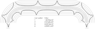
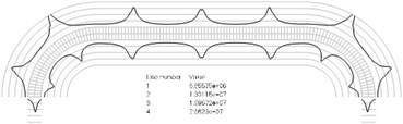
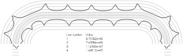
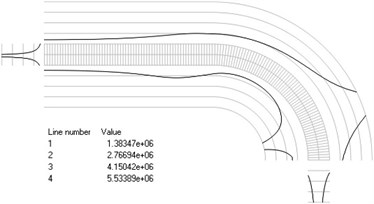
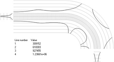
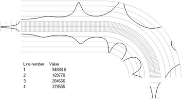
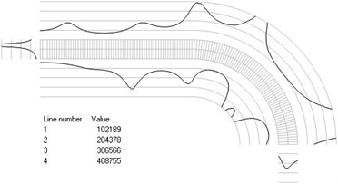
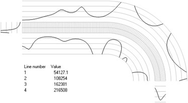
Numbers of cycles till the start of wear on the surfaces of the Braille element are represented graphically in the normal direction to the boundaries of the structure. The value of parameter changes only the scale in the normal direction to the boundaries of the Braille element in the graphical relationships describing the numbers of cycles till the start of wear. The value of parameter in the following representation is assumed as 1. Numbering of lines equidistant in the normal direction to the surfaces of the structure is shown in Fig. 1. Numbers of cycles till the start of wear for the first ten eigenmodes are presented in Fig. 2.
Fig. 1Numbering of lines equidistant in the normal direction to the surfaces of the structure for the plane strain problem
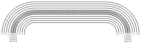
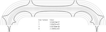
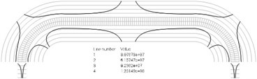
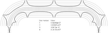
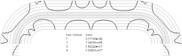
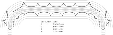
Fig. 2Numbers of cycles till the start of wear for the plane strain problem: a) the first, b) the second, …, j) the tenth eigenmodes. Finite element mesh and four lines of equal distance from the surfaces of the Braille element in the normal direction are shown in grey colour. At the places of minimum distance in the normal direction from the surface of the Braille element to the black curve deterioration of quality of material starts to develop. For different eigenmodes deterioration of quality of material starts to develop at different places of the Braille element. The number of cycles till the start of wear is calculated on the basis of Eq. (2)
a)
b)
c)
d)
e)
f)
g)
h)
i)
j)
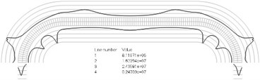
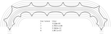
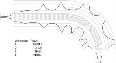
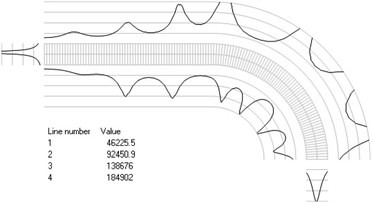
Fig. 3Numbering of lines equidistant in the normal direction to the surfaces of the structure for the axisymmetric problem
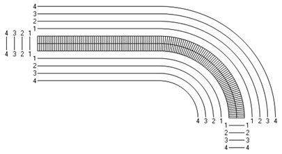
3.2. Axisymmetric problem
The structure consists of one row of elements located on a straight part with the length equal to the length of the middle line of one fourth of a circle and then of one fourth of a circle. The radius of the middle line of the part of the circle is 0.001 m and semi thickness of the structure is 0.0001 m. The following parameters are assumed: modulus of elasticity 6∙108 Pa, Poisson’s ratio 0.3, density of the material 785 kg/m3. The left end of the structure coincides with the axis of symmetry.
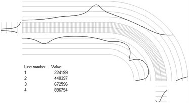
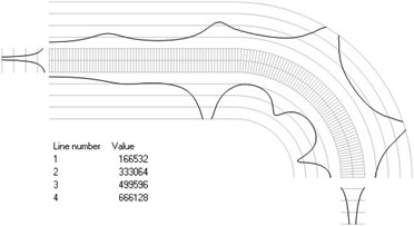
Fig. 4Numbers of cycles till the start of wear for the axisymmetric problem: a) the first, b) the second, …, j) the tenth eigenmodes
a)
b)
c)
d)
e)
f)
g)
h)
i)

j)
Displacements in the direction of the axis of the three nodes on the left end of the structure are assumed equal to zero. All displacements of the three nodes on the right end of the structure are assumed equal to zero.
The value of parameter in the following representation is assumed as 1. Numbering of lines equidistant in the normal direction to the surfaces of the structure is shown in Fig. 3. Numbers of cycles till the start of wear for the first ten eigenmodes are presented in Fig. 4.
The obtained results are used in experimental procedures for measurement of wear of Braille elements. From the presented numerical results it is seen that deterioration of quality of polymeric materials used for Braille elements starts at definite places of the Braille element. Those places are different for resonant vibrations according to different eigenmodes. But the applied numerical model is a simplified one. In order to obtain more accurate results detailed physically nonlinear behavior of the polymeric material should be taken into account. Thus it is important to investigate the agreement between the obtained numerical results and experiment. For this purpose extensive experimental investigations were performed and some basic results from them are presented further.
4. Microscopic study of resistance to wear and physical qualities of Braille formed on polymeric and biodegradable materials
4.1. Materials and methods
Experimental tests were performed using samples with Braille formed on polymeric materials that are used for packages or labels with Braille. Polymer PP, polymer PET and biodegradable materials were used in the process of testing. Characteristics of investigated materials are listed in Table 1 which is based on the data given in [12].
Table 1Characteristics of basic types of polymeric materials used in the process of investigations
Parameters | Samples | |||
Polymer PET | Polymer PP | Biodegradable No. 1 | Biodegradable No. 2 | |
Tensile strength (MPa) | 172 | 29.3-38.6 | 11.68-12.44 | 8.85-11.07 |
Elongation at break (%) | 12-55 | 100-600 | 266-566 | 63.8-107.3 |
Thickness (mm) | 0.24 | 1.0 | 0.15 | 0.18 |
Composition | – | – | LDPE, glycerin 1 %, potato starch 3 % | LDPE, glycerin 1 %, potato starch 5 %, itaconic acid 10 % |
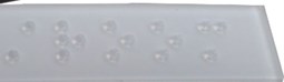
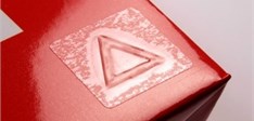
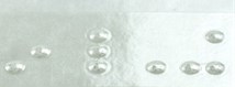
The investigated samples with Braille or relief elements were printed using screen printing and clear plastisolic inks on polymers PP and PET (see Fig. 5(a)). The second method was to print Braille elements using rotary press of screen printing type that also was integrated in flexographic printing machine. Also special clear inks Marabu UVLB1 and screen BZ were used for printing of Braille elements on polymer PP (see Fig. 5(b)). The third method was to emboss the Braille elements of polymer PP, PET (see Fig. 5(c)) and of biodegradable materials No. 1 and No. 2. It was investigated how the mechanical effect of wear changes the geometrical parameters of Braille dots.
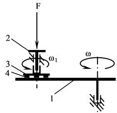
Experimental setup of Oser type was used for determination of change of geometrical parameters of Braille under cyclic wear (see Fig. 6). Testing conditions were close to the ones which are experienced in the process of exploitation. Planetary motion was provided to the sample and the linear velocity of each sample dot was the same. The pressing force of the sample holder was 1.96 N and the linear velocity was 0.47 m/s. The duration of mechanical effect was changed from 1 min to 60 min. The value of pressing force was chosen on the basis of the pressing force of fingers of blind people in the process of Braille reading.
Fig. 5Investigated samples of Braille or relief elements: a) Braille printing using screen printing with clear plastisolic inks on polymers PP and PET, b) label with relief element printing with Marabu UVLB1 inks on polymer PP, c) Braille formed using embossing of polymer PP, PET and of biodegradable materials No. 1 and No. 2
a)
b)
c)
Fig. 6Scheme of experimental setup of Oser type for determination of change of geometrical parameters of Braille under cyclic wear and for determination of resistance of Braille dot to mechanical effects: 1 – disc, 2 – holder, 3 – disc of sample, 4 – sample, F – pressing force, ω, ω1 – angular velocities of rotation of the disc and of the disc of sample
Braille dot height and diameter were measured using FAG BRAI³ Braille Dot Checker. The changes of Braille dot parameters were measured before and after mechanical effects, i. e. after 60 min or wearing path of 1692 m (see Fig. 7).
Qualitative analysis of surfaces of Braille dots was carried out using digital optical microscope Optika M – 699 LWPDPLAN at zooming levels of 75× and 150×. Digital images were captured before and after wear.
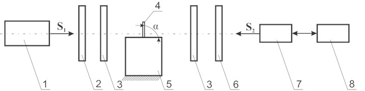
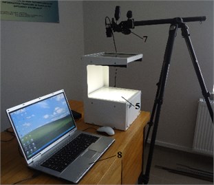
A polymeric film usually is made from optically isotropic material in which stresses take place. This can have a negative effect to the Braille parameters [13]. Method of photo-elasticity was used for determination of distribution of stresses in the investigated polymeric material with Braille dots or relief elements. Special experimental setup was designed. Schematic representation of the experimental setup and its general view are shown in Fig. 8. Levels of stresses were evaluated at static states of the investigated samples. Colour patterns captured in the process of testing were analysed according to the methodology provided by the company “Sharpless”. Colour patterns of stresses were captured using digital camera EO – 1312c.
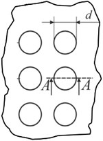
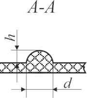
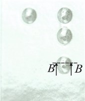
Fig. 7Schematic views of the investigated samples: a) Braille view from top: d – dot diameter; b) side view of Braille formed using screen printing on polymeric material (A–A): h – Braille dot height, d – Braille element width; c) Braille embossed on polymer; d) profile of Braille element (B–B): h – Braille element height, d – Braille element width
a)
b)
c)
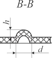
d)
Fig. 8Experimental setup used for determination of levels of stresses: a) structural scheme of the experimental setup where: 1 – light source, 2 – polarizer, 3 – quarter wavelength plate, 4 – sample, 5 – base on which the sample is placed, 6 – analyzer, 7 – digital camera EO – 1312c, 8 – personal computer, S1 – direction of incident light beam, S2– viewing direction, α – slope angle of polymeric film; b) general view of the experimental setup
a)
b)
4.2. Results and discussion
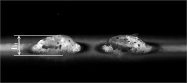
Braille dots were formed using plastisolic inks on polymer PP (see Fig. 9(a)). Laminates from the polymeric material after applying mechanical effects were investigated. Thus the Braille dot height decreases by 33 %. Before testing Braille dot height was 0.39 mm, while after applying mechanical effect for the time period of 60 min Braille dot height was 0.26 mm (see Fig. 9(b)).
Fig. 9Digital images of Braille dots formed using screen printing on polymer PP: a) before testing; b) after applying mechanical effect for the time period of 60 min. Deterioration of quality of polymeric material is clearly seen from the visual comparison of both images. From the presented images it is seen that the height of the Braille dot h= 0.39 mm (see Fig. 9(a)) after application of the mechanical effect became smaller and is equal to h1= 0.26 mm (see Fig. 9(b))
a)
b)
During the time period of application of mechanical effect the loading force presses the relief elements formed using plastisolic inks. These inks are also made from polymeric materials, thus they deform under external applied mechanical force which is bigger than intermolecular force.
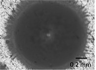
Digital images of microscopic analysis are shown in Fig. 10.
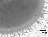
Braille dots formed using screen printing on polymer PET are hardly readable. Thus their further investigations were not carried out (see Fig. 11).
Braille formed using special Braille inks such as Marabu UVLB1 can be noted for especially high resistance to mechanical effects. Thus geometrical parameters for this type of Braille elements are not changing (see Fig. 12).
Fig. 10Digital images of Braille formed using plastisolic inks on polymer PP before testing at different zooming levels: a) 75×; b) 150× and after application of mechanical effect at different zooming levels: c) 75×; d) 150×. Estimation of quality of polymeric material is performed visually on the basis of presented images. From the presented images it is seen that the surface of dots printed in polymeric material PP by using the trapharetic method (see Fig. 10(a) and Fig. 10(b)) after application of the mechanical effect changes (see Fig. 10(c) and Fig. 10(d)). This phenomena takes place because of the fact that plastisolic paint under the action of mechanical effect experiences irreversible compression
a)
b)
c)
d)
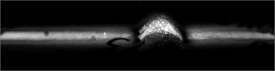
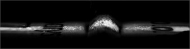
Fig. 11Digital image of Braille dot profiles formed using screen printing on polymer PET. As seen from the presented image Braille dots on the material of PET type formed by using trapharetic printing with plastisolic paints were obtained with insufficient height: they are hardly readable and thus they cannot be recommended for applications
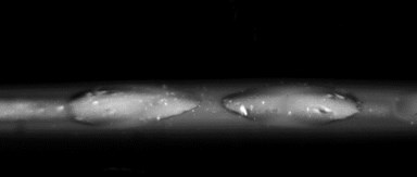
Fig. 12Digital images of Braille formed using special inks on polymer PP: a) before mechanical effect and b) after application of mechanical effect. From the images it is seen that the height of the Braille element formed by trapharetic printing with special paint Marabu UVLB1 (see Fig. 12(a)) after application of the mechanical effect did not change (see Fig. 12(b)). This indicates especially high resistance to mechanical effects and the fact that geometrical parameters for this type of Braille are not changing
a)
b)
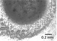
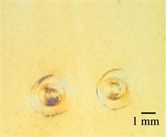
It can be seen that color patterns of stresses are similar for both PET and PP materials (see Fig. 13(a) and Fig. 13(b)) and biodegradable elements (see Fig. 13(c) and Fig. 13(d)). It was noticed that the use of embossed Braille in biodegradable materials is not suitable because Braille elements collapse in time, that is the material experiences relaxation. This effect was especially observed in the investigated sample No. 1 (see Fig. 14).
From the presented numerical and experimental results, it is seen that deterioration of quality of polymeric materials used for Braille elements starts at definite places of the Braille element. This indicates the qualitative agreement between the performed numerical and experimental investigations. But one is to have in mind that the applied numerical model is a rather simplified one. In order to obtain quantitative agreement between the numerical and experimental investigations detailed physically nonlinear behavior of the polymeric material should be taken into account.
Fig. 13Distribution of stresses in Braille and relief elements formed using embossing on polymeric materials: a) PET, b) PP and biodegradable polymeric films: c) No. 2, d) No. 1. From the presented images it is seen that color patterns of stresses are similar for both PET and PP materials (see Fig. 13(a) and Fig. 13(b)) and for biodegradable elements (see Fig. 13(c) and Fig. 13(d))
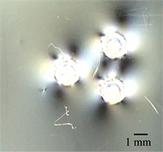
a)
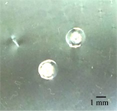
b)
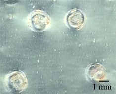
c)
d)
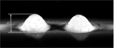
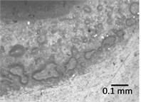
Fig. 14Digital images of Braille formed on biodegradable materials: a) No. 1 and b) No. 2. From the images it is seen that the Braille dots formed in biodegradable polymeric materials by using the method of pressing are of insufficient height as well as the relaxation of material has substantial effect in them (see Fig. 14(b))
a)
b)
5. Conclusions
Plane strain and axisymmetric problems are investigated. Equivalent stresses for the first eigenmodes are obtained. Thus the places with maximum stresses can be determined. From experimental investigations it is noticed that deterioration of quality of Braille element usually starts from the surfaces of the investigated sample. This indicates that the results of equivalent stress on the surfaces of Braille element are of special importance. At the places of maximum equivalent stress defects in the material usually start to develop after a number of cycles of loading.
The number of cycles till the start of wear for each eigenmode is calculated. Numbers of cycles till the start of wear on the surfaces of the Braille element are represented graphically in the normal direction to the boundaries of the structure. The presented material is used for experimental determination of the number of cycles till the start of wear of a Braille element.
During experimental tests it was determined that geometrical parameters of Braille are changing in the process of application of mechanical effects. The changes of geometrical parameters of Braille depend on materials used for Braille elements.
The levels of stresses that take place around the Braille elements that are formed using embossing on polymeric materials are not high. It was determined that biodegradable materials are not suitable for use in embossed Braille elements because they are characterized by relatively high plasticity and sharp relaxation properties.
From the presented numerical and experimental results, it is seen that deterioration of quality of polymeric materials used for Braille elements starts at definite places of the Braille element. This indicates the qualitative agreement between the performed numerical and experimental investigations.
References
-
Yun-Xuan Weng, Xiu-Li Wang, Yu-Zhong Wang Biodegradation behavior of PHAs with different chemical structures under controlled composting conditions. Polymer Testing, Vol. 30, Issue 4, 2011, p. 372-380.
-
Siracusa V., Rocculi P., Romani S., Rosa M. D. Biodegradable polymers for food packaging: a review. Trends in Food Science and Technology, Vol. 19, Issue 12, 2008, p. 634-643.
-
Fagiani R., Massi F., Chatelet E., Berthier Y., Sestieri A. Experimental analysis of friction-induced vibrations at the finger contact surface. Proceedings of the Institution of Mechanical Engineers, Part J: Journal of Engineering Tribology, Vol. 224, Issue 9, 2010, p. 1027-1035.
-
Kim M. S., Young Kim I., Kyu Park Y., Ze Lee Y. The friction measurement between finger skin and material surfaces. Wear, Vol. 301, 2013, p. 338-342.
-
Childs T. H. C., Henson B. Human tactile perception of screen-printed surfaces: self-report and contact mechanics experiments. Proceedings of the Institution of Mechanical Engineers, Part J: Journal of Engineering Tribology, Vol. 221, Issue 3, 2007, p. 427-441.
-
Zienkiewicz O. C. The Finite Element Method in Engineering Science. Mir, Moscow, 1975, (in Russian).
-
Bathe K. J. Finite Element Procedures in Engineering Analysis. Prentice-Hall, New Jersey, 1982.
-
Segerlind L. J. Applied Finite Element Analysis. Mir, Moscow, 1979, (in Russian).
-
Gallagher R. H. Finite Element Analysis Fundamentals. Mir, Moscow, 1984, (in Russian).
-
Samul V. I. Basis of the Theory of Elasticity and Plasticity. Vysshaja Shkola, Moscow, 1982, (in Russian).
-
Kovaliov N. A. Applied Mechanics. Vysshaja Shkola, Moscow, 1982, (in Russian).
-
Beswick R., Dunn D. Plastics in Packaging. Western Europe and North America. Rapra Technology Limited, 2002, p. 141.
-
Standard LST EN 15823:2010 Packaging – Braille on Packaging for Medicinal Products.
About this article

The authors thank the reviewers for a number of valuable comments. They enabled to substantially improve the paper. This work was prepared in the frame of the Project “Creation of Biodegradable Polymer Packing Materials and Research of Physical and Mechanical Properties” within the Lithuanian – Belarus Partnership Programme for Bilateral Cooperation in the Field of Science and Technologies (Agreement No. TAP LB – 02/2015, project duration: 2015 – 2016, project leaders: professors E. Kibirkštis and V. Kuzmich). Also this work is supported by JSC “Aurika” (Support Agreement No. SV8 – 0067 2015.10.12).
All authors declare that all of them have made contributions to the paper. I. Venytė performed development of the experimental setup used for the investigations and interpretation of the obtained results of experimental measurements, together with other authors took part in the development of the numerical model. E. Kibirkštis proposed the experimental setup used for investigations, performed the interpretation of experimental results, took part in the development of the numerical model. V. Miliūnas enhanced the developed experimental setup used for investigations and investigated the correspondence between experimental and numerical results. K. Vaitasius performed review of literature and together with other authors performed experimental measurements. A. Stepanenko created the formulation and manufactured the biodegradable materials. K. Ragulskis proposed the numerical model and performed the interpretation of the obtained numerical results. L. Ragulskis performed the computer implementation of the graphical output of results of calculations.
