Abstract
The dynamical characteristics research of planetary gear system with tooth pitting is useful for early fault diagnosis and monitor. However, it is an unsolved puzzle to establish the relationship between tooth pitting and dynamical characteristics. In this study, a pitting fault analytical model is proposed to investigate the effects of tooth pitting on the gear mesh stiffness. Then this mesh stiffness with tooth pitting is incorporated into a dynamical model of planetary gear system, and the effects of the tooth pitting on the vibration characteristics is investigated. The simulated results show that the time-varying mesh stiffness is reduced with tooth pitting propagations along width or depth direction. The mesh frequency and its harmonics are mainly frequencies components in the frequency spectrum of dynamic mesh force, but sidebands caused by the tooth pitting are more sensitive than the mesh frequency and its harmonics. The tooth pitting frequency and its harmonics also increase with the rising rotational speed of the sun gear. In addition, both relative statistical indicators of RMS and Kurtosis increase with the growth of tooth pitting size. But the relative indicators have different sensitivity on the vibration signal type. These results could supply some guidance to the condition monitoring and fault diagnosis of planetary gear system, especially to the gear tooth pitting at early stage.
1. Introduction
Planetary gear system has a lot of advantages such as large transmission ratio, compact structure, and power split, is widely used in wind turbine. Due to severe working environment and complicated load, the failure of planetary gear transmission system is accounted for 20 % in total wind turbine equipment failure [1]. Tooth pitting is as one of the mainly types of gear failure in the planetary gear transmission system, the study of its fault signals is of great significance to early fault diagnosis and condition monitoring of the planetary gear transmission system.
The current researches on dynamical characteristics of planetary gear system are mainly concentrated on the dynamical model and the dynamical behavior. Kahraman et al. [2] established a coupling model including transverse, longitudinal and torsional direction displacement, time-varying stiffness, backlash etc. Parker et al. [3, 4] developed a coupled model to analyze the natural modes, mesh phasing, ring deformation effects, etc. Some other research topics about planetary gear system are mainly concentrated on the load sharing [5, 6], nonlinear dynamics [7, 8] and transmission errors [9, 10]. In the study of gear faults, some scholars have carried out the study of crack fault [11-14], wear [15, 16] on the fixed axis gear system. Chaari [17] have also studied on the influence of manufacturing errors on the dynamic behaviors of planetary gears through the frequency domain and energy analysis method. Besides Sharad et al. [18] studied the bearing inner and outer ring fault of the planet gear on the dynamical response. But the dynamical characteristics research of planetary gear with pitting fault is still less. In addition, the vibration transfer path of the planetary gear system is more complex and the fault response is not obvious. And those high-power planetary gear sets work in the environment of low speed and heavy load, have the complicated low characteristic frequency compositions. It is difficult to analyze those fault characteristic frequencies. So the research on the dynamical modeling and theoretical analysis of planetary gear system with pitting is imminent.
In this paper, the effects of gear pitting are integrated within the mesh stiffness based on the potential energy method. Then a dynamical model of four-planet-gear planetary gear system used in the wind turbine is employed with pitting mesh stiffness. Further studies about the influence of pitting on the system dynamical response are executed, and fault characteristic are also analyzed. This research is expected to supply the theoretical information for the condition monitoring and fault diagnosis of planetary gear system used in the wind turbine.
2. Numerical calculation of tooth deformation and mesh stiffness
The studies on the time-varying mesh stiffness have been published in many former works. However, it appears that the reconstruction of these stiffness parameters directly from the results of the numerical modeling or the finite element method is very difficult. And few studies consider the pitting faults in the calculation model. Here, the original gear mesh stiffness formulation is employed based on the work by Wu et al. [19], and Tian et al. [20]. The total potential energy in a pair of meshing teeth includes the summation of the Hertz energy term , bending energies term , shear energy term and compressive energies term . These potential energy along the mesh line can be obtained by:
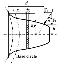
where is the area moment of inertia, is the area of the section, is mesh force along the action of force, and are the Young modulus and the shear modulus, , , , , , , are shown in the Fig. 1, and is moment of and h.
Fig. 1Model of the spur gear tooth as a non-urtiform cantilever beam with pitting
a) Single tooth mesh stiffness
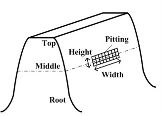
b) Pitting direction
Yang and sun’s studies [21] have shown that Hertz contact stiffness is constant in the direction of the line of action, and is independent with the contact position and the interpenetration depth. It is only proportional to the tooth width. The specific calculation method of Hertz contact stiffness is given as follows:
where is the Poisson’s ratio, and is the tooth width.
Accordingly, for a pair of meshing teeth, the total mesh stiffness can be expressed as follows:
where subscript represents the sun gear or ring gear, and subscript represents th planet gear; , , represent mesh stiffness of th planet gear caused by the bending deformations, shear deformations and compressive deformations, respectively; , , represent mesh stiffness of gear caused by the bending deformations, shear deformations and compressive deformations, respectively; and denotes mesh stiffness caused by Hertz contact.
Pitting is produced by local stress concentration of tooth surface in the case of the fatigue. After working for a long time, tooth surface contact fatigue could cause tooth pitting faults. Then a depth of the 0-1000 μm pit could appear [22]. These pitting faults can change the actual meshing tooth width , the area moment of inertia and the area of the section . As shown in Fig. 1, pitting will change the single tooth cross-sectional area of the beam, impact the bending deformation, compression deformation and shear deformation. Then the mesh stiffness of single gear with pitting will be obtained as follows:
where and are mesh stiffness integral unit along tooth width with pitting and without pitting, respectively; , , represent bending stiffness, shear stiffness, and compressive stiffness, respectively; is the total mesh stiffness with pitting caused by bending stiffness, shear stiffness, and compressive stiffness; , are the starting position and ending position of pitting fault along tooth width, respectively.
With the joint of Eq. (3) and (4), the changing total mesh stiffness of a gear pair with pitting faults can be obtained.
3. Effect of the tooth pitting on the mesh stiffness
As the pitting expansion direction is defined by the Fig. 1, a group of pitting faults on the sun gear is employed to study the effects on mesh stiffness. These pitting faults are defined as a depth of 1 mm, a height of 1 mm and width of 10 mm 15 mm, 20 mm, 50 mm, respectively. And pitting faults are on the location of the middle tooth surface along height direction. In the whole sun gear and planet gear (S-P) meshing process, meshing position is gradually moved from the tooth top to the tooth root.
Fig. 2The effects of pitting width to the S-P mesh stiffness (single-tooth mesh)
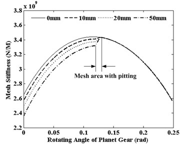
Fig. 3The effects of pitting depth to the S-P mesh stiffness (double-teeth mesh)
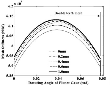
Fig. 2 displays the effects of pitting width on single tooth mesh stiffness of sun gear when planet gear is rotate. It can be seen from the Fig. 2, pitting width does not affect on the mesh cycle of mesh stiffness, but affect on the value of mesh stiffness. And distinct reduction of mesh stiffness also can be observed when pitting grows along the tooth width.
To study the effects of pitting depth to mesh stiffness, a group pitting faults are employed in the middle tooth surface of sun gear. These pitting faults include a height of 1mm, a width of 10 mm, and the depth of 0.2 mm, 0.4 mm, 0.6 mm, 1.0 mm, respectively. The effects of the pitting depth to double teeth area of S-P mesh stiffness are displayed in Fig. 3. From the Fig. 3, pitting depth also does not affect on the mesh cycle of mesh stiffness, but affect on the value of the mesh stiffness. And the stiffness reduction increases with the growth of pitting depth.
Fig. 4The effects of pitting positions to the S-P mesh stiffness
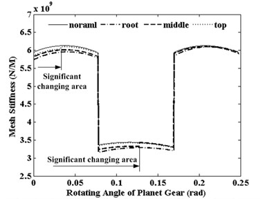
To observe the effects of pitting position to mesh stiffness along the tooth height direction, only a pitting fault is taken as a depth of 1 mm, a height of 1 mm, a width of 50 mm. And this pitting fault is assumed three positions on the tooth, the root, the middle and the top, respectively. Fig. 4 shows the effects of the pitting fault on the total mesh stiffness of S-P mesh. It can be seen from the Fig. 4, pitting fault can effect on the mesh stiffness in a meshing period starting time. All the stiffness values will decrease when pitting fault appears. The maximum stiffness decreases appear in the case of pitting fault in tooth top. And this significant changing area only happens in the area of double teeth meshing. The minimum stiffness decreases appear in the case of pitting fault in tooth root. In the mesh cycle, the ending time of the significant changing area with pitting in is root later than in top.
4. The influence of the tooth pitting on the dynamical response
Based on the mesh stiffness model of gear pair with or/and without a pitting fault, a lumped parameter dynamical model of flexible pin type four-planet gear system used in the wind turbine is established. The mainly structural parameters of this planetary gear system are listed in Table 1. The dynamical model of the planetary gear system is shown in Fig. 5 based on the lumped parameters.
In this dynamical model of lumped parameters, each component has vibration amplitudes in the three degrees of freedom with rotation and two translations. The vibration amplitudes of the sun (), carrier () and ring () are one rotation and two translations , . And the vibration amplitudes of th planet gear (rotational), (tangential), (radial) 1, 2, 3, 4 are defined in a rotating carrier reference frame which is fixed to the carrier with the origin at point O.
Table 1Structural parameters of the planetary gear train
Parameters | Sun | Planet | Carrier | Ring |
Number of Teeth | 21 | 37 | – | 95 |
Modulus (mm) | 15 | 15 | – | 15 |
Tooth width (mm) | 300 | 300 | – | 300 |
Mass (kg) | 205 | 289 | 1596 | 1538 |
(kg) | 199 | 271 | 1847 | 1681 |
Base circle diameter (mm) | 286 | 503 | 435 | 1292 |
Pressure angle (°) | 25 | |||
Supporting stiffness (N/m) | 1.32×10⁶ | 2.13×10⁸ | 9.85×10⁹ | 1.01×10¹⁰ |
Torsional stiffness (N/m) | 5.00×10¹⁰ | 0 | 0 | 0 |
Fig. 5The dynamical model of planetary gear system with twenty-one degrees of freedom
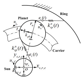
The supporting bearings and gear mesh stiffness along line of action are modeled by linear springs. are the supporting stiffness of the planet gear. And the rotational motion of the constrained ring gear is described as a high stiffness value spring. is angular velocity of the carrier. The dynamic transmission error of the sun gear and planet gear () and ring gear and planet gear () along the line of action are expressed as and , respectively, can be determined as:
where and are the meshing angles of the gear pairs and , respectively. and are the projected angles of the sun gear and the ring on the coordinate of the planets, ,. , are the static transmission errors of the gear pairs and , respectively.
With the Lagrange formulation, all lumped parameters motion equations for the components , , and the planets can be assembled in matrix forms as:
where is the vector of the displacements of the system; is the matrix of the masses of the system; and are the gyroscopic matrix and the centripetal stiffness matrix, respectively; is the angular speed of carrier, is the matrix of the supporting stiffness of the system; is the matrix of the mesh stiffness of the system; is the vector of the external torques; is the excitations due to the static transmission errors.
To the planetary gear system, pitting is the easiest to occur on the sun gear or the planet gear. And the dynamic mesh force (DMF) of sun gear and planet gear (S-P) are most easily affected by the pitting. From Eqs. (5) and (6), DMF between the gear pair of sun(ring) gear and planet gear mesh can be calculated as:
For the convenience of calculation, the carrier in a counterclockwise direction is defined as the positive direction. Then the rotational frequency of sun gear, carrier and planet gear (, , ) can be got from the input speed of sun gear. To get the gear mesh frequencies and pitting fault frequencies, a rotational speed is applied to the whole planetary gear system along the carrier rotating in the opposite direction. The planetary gear system can be changed to a new fixed axis gear system. At this point, the new equivalent rotational frequency of the sun, planets, planet carrier and ring are changed as , 0, , respectively. The mesh frequency also can be got from the new fixed axis gear system. When the pitting occurs on the surface of the sun gear, the sun gear rotates on its axis a round, and pitting tooth can mesh once with every planet gear in the new equivalent system. The planet with pitting is similar. Then the pitting fault frequency on sun gear and the planet gear and can be obtained from Eq. (8):
From the Table 1, the characteristic frequencies of the planetary gear system can be obtained in the form of , as shown in table 2.
Table 2Characteristic frequencies of the planetary gear system (unit: Hz)
Characteristic frequencies | |||||
Values | 17.20 | 0.18 | 0.28 | 3.28 | 0.47 |
As a result of gear meshing, the pitting in the middle of the tooth high direction is the most common type. Here, a group of pitting faults are taken as a depth of 0.5 mm, a height of 1 mm, a width of 50 mm, and are located in the tooth middle position along high direction of sun gear. In order to observe the dynamical response in the case of pitting, the sun gear’s input speed is changed from 0 to 1000 r/min. Fig. 6 shows the dynamic mesh force (DMF) of S-P with sun tooth pitting in the case of 300 r/min. In the Fig. 6(a), the DMF curve of S-P mesh in time domain is changed every 16.4 mesh cycle. This means that pitting tooth will mesh with each planet gear on every 3.6 mesh cycle. From Fig. 6(b), the vibration signal of DMF is mainly composed of mesh frequency (86.0 Hz), sun gear pitting fault frequency (16.4 Hz) and their harmonics. Besides, the corresponding spectrum shows that a lot of side-frequencies are observed on both sides of mesh frequency and its harmonic compositions. The interval between adjacent two side-frequency is 16.4 Hz, which is equal to sun gear pitting fault frequency of the first Eq. (8).
Fig. 6Dynamic mesh force (DMF) of the planet gear and the sun gear with tooth pitting
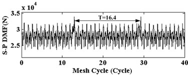
a) Time domain
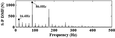
b) Frequency spectrum
Although spectrum diagram is clear in Fig. 6, the sun gear pitting fault frequencies are included in the side-frequency components. But the mesh frequency and its harmonic frequencies are still contained. It is not easy to directly observe the change of the fault characteristic. To further extraction of sun gear pitting fault characteristic signal, dynamical response of DMF is dealt with by band-pass filtering and Hilbert envelope demodulation. Mesh frequency and harmonic frequencies are inhibited, and only pitting frequency and its harmonic frequencies are extracted. Then in the range of 0-1000 r/min of sun gear rotating speed, the DMF waterfall diagram of S-P mesh with the same sun gear pitting is shown in Fig. 7. As can be seen from the Fig. 7, pitting fault frequency and the first three harmonic frequencies are mainly components. And the response amplitudes will increase with rotational speed increase of sun gear. But the amplitudes are only sensitive to some sun gear rotating speeds, such as 300 r/min or 700 r/min. These amplitudes are bigger in these pitting fault frequencies and harmonic frequencies. In addition, Fig. 8 show that is the DMF waterfall diagram of S-P mesh with the same sun gear pitting in the range of 0-60×103 N·m of sun gear load. From Fig. 8, pitting fault frequency and the first three harmonic frequencies also can be observed under different load. And the DMF amplitude will increase with load increase of sun gear.
Fig. 7Waterfall diagram of DMF of S-P mesh with pitting on the sun gear
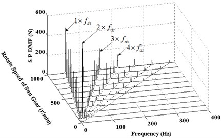
Fig. 8Waterfall diagram of DMF of S-P mesh with pitting on the sun gear
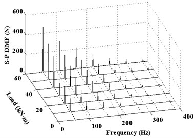
Fig. 9Frequency spectrum corresponding to DMF of S-P mesh with pitting width
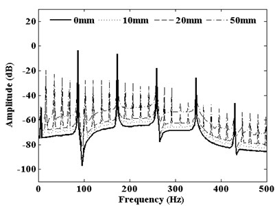
Fig. 10Frequency spectrum corresponding to DMF of S-P mesh with pitting depth
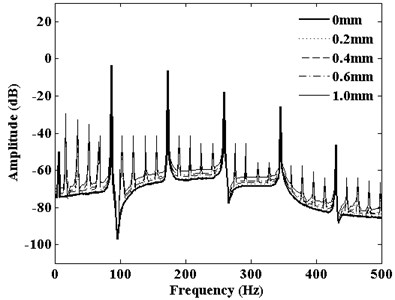
DMF vibration spectrum curve with the growth of the pitting width in the range of 0-50 mm is shown in Fig. 9. From the picture, compared with healthy teeth, mesh frequency and its harmonic frequencies dominate the vibration response of the planetary gear system when pitting occurs. And a large number of side-frequencies appear around the mesh frequency and its harmonic frequencies. Similarly, this phenomenon also causes the DMF vibration spectrum curve with changing pitting depth. Fig. 10 shows that DMF spectrum curve with changing pitting depth in the range of 0-1 mm. These side-frequencies include the pitting fault characteristic information. With pitting width or depth increase, the amplitudes of the mesh frequency and its harmonic frequencies rapidly rise. But the amplitudes of mesh frequency and harmonic components are not sensitive to pitting width or depth. Only side-frequencies are sensitive to the expansion of pitting size. So using this phenomenon of amplitude changes to monitor the occurrence of pitting tooth and expansion could be an effective method.
Some statistical parameter factors of reflecting the vibration level indicators are widely used in mechanical fault detection. In order to study the influence of pitting size to vibration response, root mean square (RMS) and kurtosis (Kurtosis) are used in here to reflect the influence extent of gear pitting. Actual calculation formula is as follows:
where is the sample data; is the length of the data; is the average of the data.
To compare the change of statistical parameters with the gear pitting size, the relative indicators of statistical parameters due to gear pitting fault can be defined as follows:
where is relative indicators of different statistical parameters; is the actual statistical parameter RMS or Kurtosis in the case of gear pitting fault. is the ideal statistical parameter RMS or Kurtosis in the case of the health condition.
Fig. 11Translation vibrations statistical indicators of planet gear versus pitting width
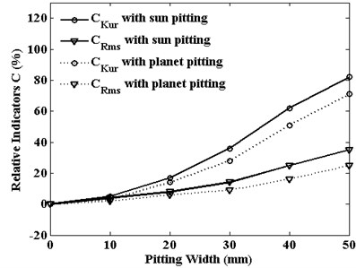
Fig. 12Rotation vibrations statistical indicators of planet gear versus pitting width
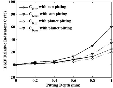
The relative statistical indicators of RMS and kurtosis are defined by Eq. (10). They are used to assess the severity of pitting fault. The trends of these two indicators of planet gear translation vibration are shown in Fig. 11, and the indicators of planet gear rotation vibration are displayed in Fig. 12. With the increase of pitting size, the amplitude of relative indicators increases. But different vibration signals have different sensitivity to relative indicators on tooth pitting propagation. For translation vibration response of planet gear, no matter what pitting is on the sun gear or the planet gear, the relative kurtosis is the most sensitive to the pitting width and relative RMS value is less sensitivity. But for rotation vibration response of planet gear, the result is just the opposite. In industrial conditions, these fault signals are easily contaminated by noise. Besides some useful measures such as install location of the sensors position and signal filtering, the choice of the suitable relative statistical indicators and vibration signal type can also be useful for planetary gear fault diagnosis and condition monitoring.
5. Conclusions
A mesh stiffness analytical model with pitting fault is derived based on the potential energy principle. Then a 21 degrees of freedom dynamical model of planetary gear system with pitting fault is proposed to study on the effects of dynamic responses. The simulated results demonstrate that the tooth pitting can result in the reduction of the mesh stiffness which will cause impulsive vibrations on the dynamic mesh force of the planetary gear system. And the deduction of mesh stiffness and the impulsive vibrations of dynamic mesh force are more serious with the growth along the pitting size. Simultaneously, the presence of the gear tooth pitting changes the frequency spectrum structure. It will generate many sidebands around the fundamental mesh frequency and its harmonics. And these side-frequencies amplitudes have significant increase with the growth of pitting size. But the presence of the pitting has little impact on the amplitudes of meshing frequency and its harmonics. From the point of fault frequency, the amplitudes of pitting fault frequency and it’s first three harmonics are mainly components. And these amplitudes will increase with the rotating speed of the sun gear. In addition, relative indicators of RMS and Kurtosis have the different sensitivity to the vibration signal type. These results could be applied in the condition monitoring and fault diagnosis of the planetary gear transmission.
References
-
Chen X. F., Li J. M., Chen H., et al. Research and application of condition monitoring and fault diagnosis technology in wind turbines. Journal of Mechanical Engineering, Vol. 47, Issue 9, 2011, p. 45-52.
-
Kahraman A. Natural modes of planetary gear trains. Journal Sound and Vibration, Vol. 173, Issue 1, 1994, p. 125-130.
-
Lin J., Parker R. G. Analytical characterization of the unique properties of planetary gear free vibration. Journal of Vibration and Acoustics – Transactions of the ASME, Vol. 121, Issue 3, 1999, p. 316-321.
-
Parker R. G., Wu X. Vibration modes of planetary gears with unequally spaced planets and an elastic ring gear. Journal of Sound and Vibration, Vol. 329, 2010, p. 2265-2275.
-
Alfred N., Montestruc P. E. Influence of planet pin stiffness on load sharing in planetary gear drives. Journal of Mechanical Design, Vol. 133, 2011, p. 014501.
-
Singh A. Load sharing behavior in epicyclic gears: physical explanation and generalized formulation. Mechanism and Machine Theory, Vol. 45, 2010, p. 511-530.
-
Guo Y., Parker R. G. Dynamic modeling and analysis of a spur planetary gear involving tooth wedging and bearing clearance nonlinearity. European Journal of Mechanics A/Solids, Vol. 29, 2010, p. 1022-1033.
-
Xu X. Y., Dong S. J., Luo J. Y., et al. The nonlinear effects of flexible pins on wind turbine gearboxes. Journal of Mechanical Science and Technology, Vol. 29, Issue 8, 2015, p. 3077-3082.
-
Zhu C. C., Xu X. Y., Liu H. J. Research on dynamical characteristics of wind turbine gearboxes with flexible pins. Renewable Energy, Vol. 68, 2014, p. 724-732.
-
Gu X., Velex P. On the dynamic simulation of eccentricity errors in planetary gears. Mechanism and Machine Theory, Vol. 61, 2013, p. 14-29.
-
Chen Z. G., Shao Y. M. Dynamic simulation of spur gear with tooth root crack propagating along tooth width and crack depth. Engineering Failure Analysis, Vol. 18, 2011, p. 2149-2164.
-
Rad A. A., Forouzan M. R., Dolatabad A. S. Three-dimensional fatigue crack growth modeling in a helical gear using extended finite element method. Fatigue and Fracture of Engineering Materials and Structures, Vol. 37, 2014, p. 581-591.
-
Pandya Y., Parey A. Failure path based modified gear mesh stiffness for spur gear pair with tooth root crack. Engineering Failure Analysis, Vol. 27, 2013, p. 286-296.
-
Guilbault R., Lalonde S., Thomas M. Modeling and monitoring of tooth fillet crack growth in dynamic simulation of spur gear set. Journal Sound and Vibration, Vol. 343, 2015, p. 144-165.
-
Saxena A., Parey A., Chouksey M. Effect of shaft misalignment and friction force on time-varying mesh stiffness of spur gear. Engineering Failure Analysis, Vol. 49, 2015, p. 79-91.
-
Wang Q. B., Hu P., Zhang Y. M., et al. A model to determine mesh characteristics in a gear pair with tooth profile error. Advances in Mechanical Engineering, 2014, p. 751476.
-
Fakher C., Tahar F., Mohamed H. Analytical investigation on the effect of gear teeth faults on the dynamic response of a planetary gear. Noise and Vibration Worldwide, Vol. 9, 2006, p. 9-15.
-
Sharad J., Hugh H. Vibration response of a wind-turbine planetary gear set in the presence of a localized planet bearing defect, ASME IMECE, 2011, p. 63452.
-
Wu S., Zuo M. J., Parey A. Simulation of spur gear dynamics and estimation of fault growth. Journal Sound and Vibration, Vol. 317, 2008, p. 608-624.
-
Tian X. H. Dynamic Simulation for System Response of Gearbox Including Localized Gear Faults. Master’s Thesis, University of Alberta, 2004.
-
Yang D. C., Su Z. S. A rotary model for spur gear dynamics. Journal of Mechanisms, Transmissions, and Automation in Design, Vol. 107, Issue 4, 1985, p. 529-535.
-
ISO/TR 15144-1 Calculation of Micropitting Load Capacity of Cylindrical Spur and Helical Gears. International Organization for Standardization, Switzerland, 2014.
Cited by
About this article

The authors would like to thank Project No. 51405048 and No. 51405047 supported by the National Natural Science Foundation of China, Project No. 2016M590861 supported by the China Postdoctoral Science Foundation, Project No. cstc2015jcyjA70012 and No. cstc2016jcyjA0514 supported by the Chongqing Research Program of Frontier and Application Foundation, Project No. KJ1500516 supported by the Scientific Research Fund of Chongqing Municipal Education Commission, Project No. Xm2015011 supported by the Special Program of Chongqing Postdoctoral Science Foundation, Project No. 310825161104 supported by the National Engineering Laboratory for Highway Maintenance Equipment, and Program of Study Abroad for Young Scholar sponsored by CQJTU for their support of this research.
In this paper, Xiangyang Xu contributed conception of the study, significantly analysis and wrote the manuscript; Shaojiang Dong performed the data analyses and manuscript preparation; Changrong Liao and Youchuan Tao helped perform the analysis with constructive discussions; Zeyin He approved the final version.
