Abstract
With thick-wall cylinders as the researched object, the paper adopts a novel cold-extrusion technology, namely electro-hydraulic cold-extrusion, to apply vibration signals into a traditional cold extrusion technology. With volume effects of vibration processing as the theoretical basis, Deform-3D software was used to conduct numerical simulation of metal materials under a traditional extrusion type and an extrusion mode with vibration respectively. Evolution processes of metal flow lines and metal grid flow under two kinds of extrusion types were analyzed and compared in details. Through experimental research, computational results of numerical simulation were verified. Metal flow lines at corners of molded parts were observed and analyzed in particular. Researched results show that the metal flow velocity increased and the bending level of cross-section flow lines of the metal decreased after applying vibration signals compared with the traditional extrusion type. The research indicated that vibration promoted metal flow, reduced resistance of the metal flow, and obtained more uniform deformation of metal materials during plastic molding. Research achievements obtained in this paper provide important theoretical and practical engineering values for effectively applying vibration in mechanical processing fields.
1. Introduction
The technology of cold extrusion molding is based on plastic molding theories of metal materials [1, 2]. At a room temperature, plastic flow is generated under high pressure and speed. A hollow part or a solid part of which the cross section is smaller than a blank cross section is molded through extrusion at the clearance between a convex die and a concave die or the concave die exit, so that a molded part with required size, shape and good mechanical properties can be obtained. Cold extrusion technology is a new technology developed on the basis of traditional metal plastic processing, featured by no or only a few of cutting chips.
In recent years, advanced cold extrusion technologies have obtained obvious achievements in mechanical manufacture. With rapid development of modern science and technologies such as computer technologies, digital design and rapid molding, the cold extrusion has been widely expanded and applied [3-5]. Compared with other manufacture technologies, the cold extrusion technology with advantages of “high quality, high efficiency, low consumption and low cost” has been extensively applied in industries such as automobile, electronic communication, light industry, national defense, aerospace and hardware [6-8].
Despite of many advantages, the cold extrusion technology has gradually showed some deficiencies in long-term production process [9-13]: (1) Extruded materials have high deformation resistance. (2) Dies get worn easily and have a short service life. (3) High requirements are proposed for blanks. (4) High requirements are proposed for cold extrusion equipment. As for these problems in the cold extrusion technologies, many scholars have made persistent efforts to find rational and scientific solutions [14-16]. Specific processing methods involve combination of new-type energy sources with metal plastic molding. For example, new energy sources such as laser, electromagnetic field, ultrasonic wave and microwave are applied [17, 18].
As for the application of ultrasonic wave-a new energy source combined with metal plastic molding, high-frequency vibration is applied to blanks or dies in general to reduce resistance and load force of blank materials and greatly improve product quality. The method of introducing vibration into cold extrusion is generated from the enlightenment of “vibration application engineering” [19-22]. “Vibration processing” refers to that during processing of metal materials, vibration excitation with certain direction, frequency and amplitude is applied to processed materials or dies, so that plastic deformation can take place to the processed materials under vibration. At present, vibration processing has been extensively applied in fields such as extrusion, punching and rolling of metal, as well as stretching of pipes and wires [23-24].
Uniformity of metal material flow during plastic molding, and rationality of metal flow line distribution are closely related to service life of dies, product quality and design of dies. Research achievements of metal flow lines provide important references for technological design and product design engineers, motivating many scholars to initiate the research on metal flow lines one after another. Huang [25] studied the metal flow and extrusion force under extrusion. Agnew [26] researched metal flow rules of brass under extrusion as well as formation mechanism of extrusion funnel, but failed to research different extrusion types. Hagenimana [27] adopted a new method of drawing grids on divided blank materials during research of metal flow phenomena under different extrusion types, but failed to research an extrusion type with vibration. Atia [28] observed metal flow lines of a bearing ring under different production technologies to distinguish the molding method of ring, which made failure analysis of products become simple and reliable. However, they failed to conduct in-depth research on processing technologies. Qin [29] analyzed metal flow lines of a Cr23Ni18 ring piece during ultrasonic detection, finding that no ultrasonic wave reflection was generated under uniform organization of metal flow lines; in case of uneven organization of metal flow lines, the difference among the metal flow lines would lead to different stripes of ultrasonic wave reflection. However, they failed to conduct detailed parameter analysis. Qamar [5] conducted many researches on influences brought by die complexity on extrusion force, product quality and die service life, but failed to conduct in-depth research on influences of metal flowing. Valberg [10] combined experiments (grid method) with finite element analysis to research metal flow characteristics of metal during plastic molding, but the research was still based on traditional processing technologies.
In conclusion, aiming at deficiencies of traditional cold extrusion processing technologies, the paper proposes a new-type cold extrusion technologies. Specifically speaking, an electro-hydraulic cold extrusion vibration experimental platform is used to apply axial sinusoidal vibration signals with certain frequency and amplitude to a concave die during cold-extrusion plastic molding of metal. With volume effects of vibration processing as the theoretical basis, Deform-3D software and experiments are used to compare and analyze evolution process of metal flow lines and metal cross-sectional grid flow lines under a traditional extrusion mode and vibration extrusion. Through research on the technology, vibration processing can play a greater role and provide better services for mechanical field and other fields, which have important theoretical significance and actual engineering significance.
2. Finite element model of traditional cold-extrusion plastic molding
2.1. Establishment of finite element model
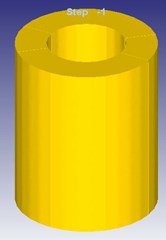
A thick-wall cylinder made of aluminum alloy is taken as the researched object in this paper. The extrusion mode of forward extrusion was adopted. Dimensions of the blank and molded part are shown in Fig. 1.
Deform-3D software is mainly applied in complicated plastic molding of metal, and simulation analysis of three-dimensional metal flow. The software takes revised Lagrange’s theorem as the theoretical basis. Rigid-plastic finite element method is taken as the core computation method, where a specially processed tetrahedron is taken as the element, so that re-division of grids becomes easier. Therefore, the paper adopted Deform-3D software to conduct forward extrusion simulation of the materials; simplified the model according to symmetry of the part; applied 1/8 of the model in the analysis to reduce computational time and increase analyzed efficiency. Solidworks software was used to establish simple geometric models of a concave die, a convex die and the blank, as shown in Fig. 2(a); generate and output the format of “stl”; input the file of “stl” format into a pre-processor of Deform-3D software. The diagram of finite element simulation model and the diagram of grid division are shown in Fig. 2.
Fig. 1Structural diagram of blank and molded part
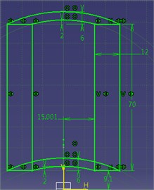
a) Cross-sectional dimensions before extrusion
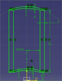
b) Cross-sectional dimensions after extrusion
Fig. 2Diagram of 1/8 model under extrusion and diagram of grid division (1 – blank; 2 – extrusion die; 3 – extrusion rod; 4 – protective jacket; 5 – core rod)
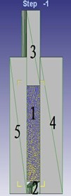
a) Geometric model
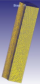
b) Finite element model
2.2. Setting of parameters of the finite element model
Basic parameters of the model are set as follows:
Basic attribute setting of blank: The blank is set as a plastic body made of aluminum alloy, corresponding to AL-1100, COLD [70F(20)] in the material library; both the convex die and concave die are rigid bodies; 20° is taken as the default temperature.
Parameter setting of grids: a tetrahedron grid with 4 nodes is taken as the grid element; automatic grid division is adopted; 36237 elements can be obtained after grid division.
Motion parameter setting of convex dice: – is set as the motion direction of convex die; motion speed is 10 mm/s.
Setting of friction conditions: shearing is taken as the friction type between die and blank; a constant friction coefficient of 0.12 is adopted.
Setting of simulation parameters: total stroke of the convex die is 40 mm, so 4000 steps are set in the simulation; data is saved for every 5 steps; computation of 0.001 s is set for each step.
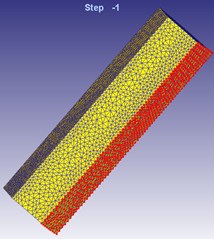
Setting of boundary conditions: in the length direction of 1/8 model, symmetric boundaries are set on the two red faces; symmetric directions are normal directions of the two faces, as shown in Fig. 3.
Fig. 3Diagram of boundary condition settings of finite element model
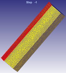
a) Symmetric plane
b) Symmetric plane 2
3. Finite element model of cold-extrusion plastic molding with vibration
Establishment process of the vibration cold-extrusion model and the traditional cold-extrusion model is basically the same. They are different in that based on the traditional modeling, a simple harmonic signal with frequency f and amplitude A is applied to the concave die.
A concave die is selected in pre-processing of Deform-3D. In the Movement module of this software, a vibration scheme is defined. In the paper, the “Function of Time” in software is used to control vibration of the concave die. During simulation of the paper, a simple harmonic signal of the set concave die with the vibration parameters including frequency 100 Hz and amplitude 0.02 mm was selected. In the paper, simulation is conducted to computational results under vibration excitations with different frequencies and different amplitudes for many times (results were compared in Fig. 13 as follows; due to the length limitation, only comparison results under 2 kinds of different amplitude are listed). Based on comparative research results combined with the experimental analysis, the simple harmonic signal with the frequency 100 Hz and amplitude 0.02 mm was finally selected as the vibration excitation parameter.
The motion control parameter of the simulation software is a speed-time function, so that the amplitude-time function shall be derived. 11 points were sampled from the applied signal during each vibration period. The speed-time values of one period are shown in Table.1.
Table 1Speed-time values in one excitation period
Time / ms | 0 | 1 | 2 | 3 | 4 | 5 | 6 | 7 | 8 | 9 | 10 |
Speed / (mm/s) | 12.6 | 10.2 | 3.9 | –3.9 | –10.2 | –12.6 | –10.2 | –3.9 | 3.9 | 10.2 | 12.6 |
4. Experimental research
4.1. Experimental system of electro-hydraulic cold-extrusion processing with vibration
The experimental system of electro-hydraulic vibration cold-extrusion processing mainly includes three sub-systems: (1) electro-hydraulic vibration excitation system, (2) cold-extrusion processing system, (3) experimental control and data collection system. The electro-hydraulic vibration excitation system is the key part of the whole experiment, which is composed of a vibration table, 2D excitation valve and hydraulic pump. The cold-extrusion processing system is a hardware condition used to complete the whole experiment, which is composed of a cold extrusion die and a hydraulic machine, where the cold extrusion die is constituted by a convex die, a concave die and a die base, etc. The experimental control and data collection system is composed of a pressure sensor, a computer and an excitation valve controller. The system is mainly used to control experimental parameters and vibration signals and collect relevant data in the experiment. The experimental system can realize cold-extrusion axial vibration under a vibration extrusion type, can control experiment parameters and collect experimental data, satisfying experimental requirements of the paper.
The electro-hydraulic vibration excitation system is mainly used to act vibration signals on the vibration table to transmit the vibration signals to the concave die of the cold-extrusion processing system. Fig. 4 shows a structural diagram of the vibration table. The vibration table is mainly composed of a top plate, a vibration cylinder elastic end cap, a vibration cylinder base-plate and sealing and fixation connectors, etc. The vibration table and the extrusion die are connected by the vibration table top plate; the concave die of the extrusion die is fixed on the upper end of the vibration table top plate; the lower end of the top plate is connected to the vibration cylinder elastic end cap. The vibration table top plate is not only used to support the extrusion die, but is also used to transmit the vibration signals to the concave die, so that axial vibration of the concave die can be realized.
The excitation valve is a core part used in work of the electro-hydraulic vibration table. The excitation valve controls output rotation speeds of a motor by input signals with different frequencies, so as to realize periodical break-over of oil liquid in the vibration cylinder in different loops and make the oil liquid pressure generate periodical changes. Structural diagram of the excitation valve is shown in Fig. 5. It is mainly composed of an AC servo motor, gear set, coupling, valve body, valve sleeve, valve core, and DC motor, etc.
Fig. 4Structural diagram of a vibration table
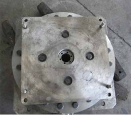
Fig. 5Structural diagram of an excitation valve

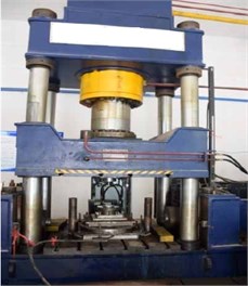
The hydraulic pump adopted in the experiment of this paper is mainly composed of an oil tank, oil pump, motor, overflow valve, electromagnetic valve and cooler. The structural diagram is shown in Fig. 6. In the electro-hydraulic vibration excitation system, the hydraulic pump is mainly used to supply oil liquid. The temperature of oil liquid in the oil tank is adjusted by the cooler (with a water cooling type), so that high oil liquid temperature can be prevented effectively. The pressure adjustment valve on the hydraulic pump is used to adjust the oil supply pressure, so that vibration amplitude of the vibration platform can be changed. The hydraulic machine of the cold-extrusion processing equipment adopted in the experiment of this paper is shown in Fig. 7.
Fig. 6Structural diagram of hydraulic pump
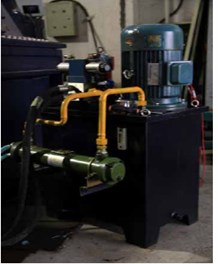
Fig. 7Structural diagram of hydraulic machine
4.2. Experimental control and collection of electro-hydraulic vibration cold extrusion
The experimental control and data collection system is mainly used to control experimental conditions, experimental parameters and vibration signals and collect relevant data. During the experiment, a switch button of the hydraulic machine is used to start or stop the hydraulic machine. A downward extrusion button is used to control the hydraulic machine to move a horizontal beam, make the convex die move downwards and extrude the blank. During the extrusion, the downward moving stroke of the convex die is controlled by a limiting block placed on the table face of the extrusion machine. After the extrusion, an upward lifting button is used to control the hydraulic machine and make the convex die move upwards to a safe position. A molded part is ejected upwards from the extruded part by an ejection button of ejection rod. A reset button of the ejection button is used for resetting the ejection rod and the ejection plate.
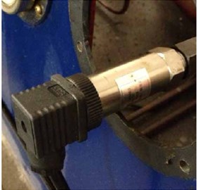
Fig. 8 shows a pressure valve of the hydraulic pump. Under applying of vibration extrusion, the amplitude of vibration signals can be changed when the pressure regulating valve is regulated to change to the output pressure. The on-site equipment controller is mainly composed of components such as an AC servo motor drive and a DSPic-based controller. Fig. 9 is the structural diagram of pressure sensor which is used to measure stroke load data during cold extrusion. The pressure sensor DY20X-C1 was selected as the sensor.
Fig. 8Structural diagram of pressure valve
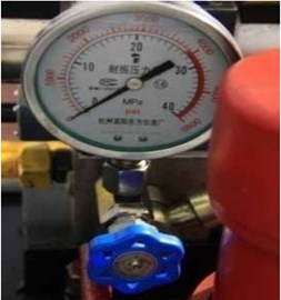
Fig. 9Structural diagram of pressure sensor
4.3. Experimental processes
The thick-wall cylinder made of aluminum alloy was taken as the researched object. After upsetting, internal stress of the blank was eliminated by annealing; surface hardness was decreased, and plasticity was increased. After that, the blank was processed by acid pickling, so that the surface oxidation layer could be removed. Through phosphorus saponification, lubricity of the blank was improved, and molding loads would be reduced. The blanking part is shown in Fig. 10(a). The extrusion experiments were conducted under fixation and vibration of the concave die, respectively. In the paper, vibration frequency is 100 Hz; vibration amplitude is 0.02 mm; oil pressure is 8 MPa. The molded part is shown in Fig. 10(b).
5. Computational results, discussion and analysis
5.1. Experimental verification of the finite element model
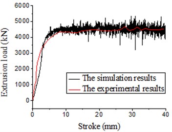
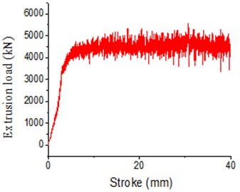
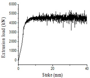
In the paper, relevant results of extrusion molding of the thick-wall cylinder were computed under two kinds of conditions including concave die fixation and concave die vibration (with excitation frequency of 100 Hz and amplitude of 0.02 mm) through numerical simulation and experiments respectively. Therefore, comparison results between experimental and numerical simulation results of the load-stroke curve under two kinds of situations are obtained, as shown in Fig. 11 and Fig. 12.
It is shown in Fig. 11 that: with application of the traditional extrusion technology, when the bottom concave die was fixed, the average extrusion force in experiments was 5.45 t; the average extrusion force of the finite element simulation was 5.5 t; the error between them was 1 %. It is shown in Fig. 12: when the vibration extrusion technology was applied and vibration took place to the bottom concave die, the average extrusion force in experiments was 4.25 t; the average extrusion force in the finite element simulation was 4.38 t; the error between them was 3 %. It is thus clear that the computational results are consistent with experimental results in this paper, verifying the high accuracy of the simulation model in this paper. In addition, above results also show that the extrusion force decreased obviously under the electro-hydraulic vibration extrusion. Besides, Fig. 13 shows that under vibration excitation extrusion with different amplitudes, the metal flow lines were almost consistent with the grid lines. They only showed tiny differences in extrusion force. Under the amplitude of 0.02 mm, the average extrusion force was lower than that under the amplitude of 0.04 mm. Meanwhile, we conducted simulation for many times. Through comparison, we can find that the optical processing and molding effects could be obtained when the vibration amplitude is 0.02 mm and frequency is100 Hz.
Fig. 10Structures of blank and molded part
a) Blank structure
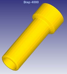
b) Structure of molded part
Fig. 11Load-stroke under traditional extrusion
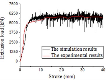
Fig. 12Load-stroke under vibration extrusion
5.2. Influences of vibration on evolution process of metal flow lines
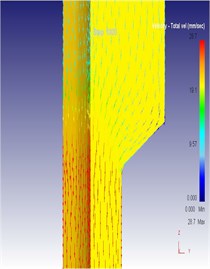
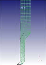
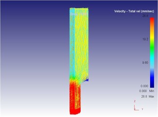
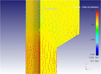
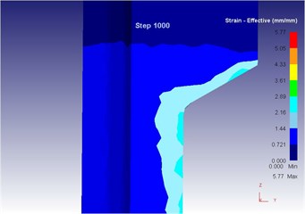
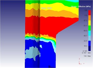
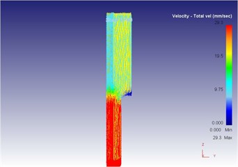
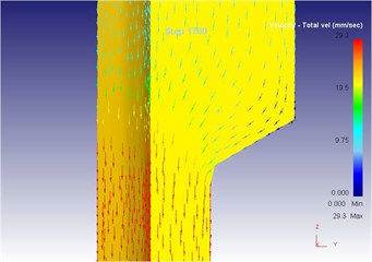
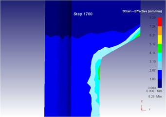
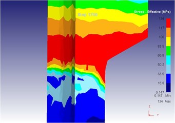
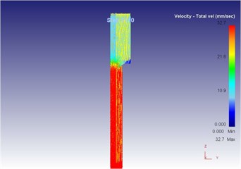
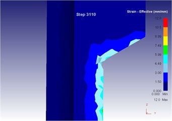
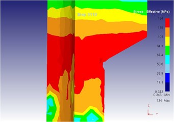
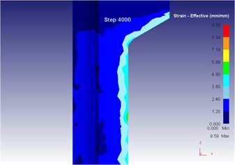
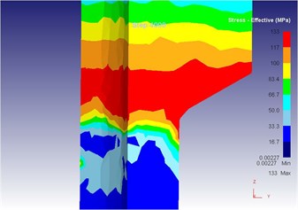
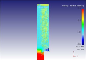
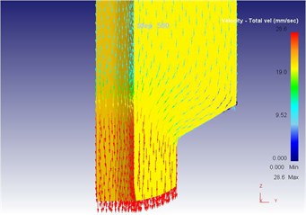
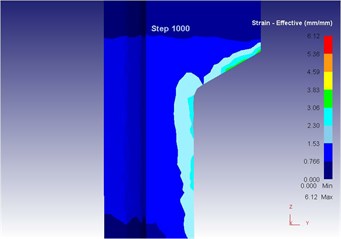
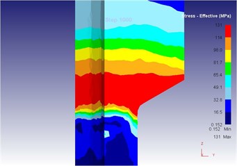
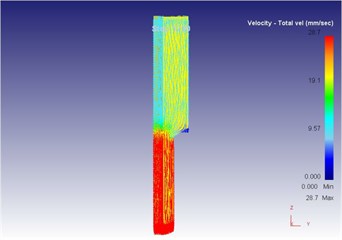
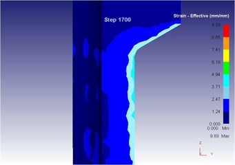
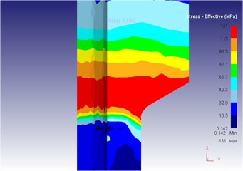
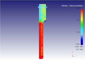
After the Deform-3D simulation, a post-processing window was used to observe three-dimensional metal flow during plastic molding of the blank. Diagrams from Fig. 14 to Fig. 18 include three-dimensional metal flow line diagrams, equivalent strain diagrams and equivalent stress diagrams of the blank in different extrusion strokes under the traditional extrusion.
As can be seen from Fig. 14 to Fig. 18, we can find: under the traditional technology, when the extrusion stoke is 5 mm, the maximum speed of blank is 29.0 mm/s, the maximum equivalent strain is 4.95, and the maximum equivalent stress is 129 MPa. When the extrusion stoke is 10 mm, the maximum speed of blank is 28.8 mm/s, the maximum equivalent strain is 5.77, and the maximum equivalent stress is 130 MPa. When the extrusion stoke is 17 mm, the maximum speed of blank is 29.3 mm/s, the maximum equivalent strain is 8.28, and the maximum equivalent stress is 134 MPa; When the extrusion stoke is 31 mm, the maximum speed of blank is 32.7 mm/s, the maximum equivalent strain is 12.0, and the maximum equivalent stress is 134 MPa. When the extrusion stoke is 40 mm, the maximum speed of blank is 28.9 mm/s, the maximum equivalent strain is 9.59, and the maximum equivalent stress is 133 MPa.
Fig. 13Diagram of computational results under different vibration amplitude: a) flow velocity of metal under different vibration amplitude; b) flow line of metal grids under different vibration amplitude; c) load-stoke of extrusion under different vibration amplitude

a1) Vibration amplitude 0.02 mm
a2) Vibration amplitude 0.04 mm
b1) Vibration amplitude 0.02 mm
b2) Vibration amplitude 0.04 mm
c1) Vibration amplitude 0.02 mm
c2) Vibration amplitude 0.04 mm
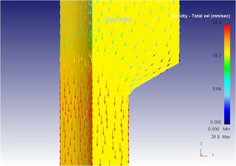
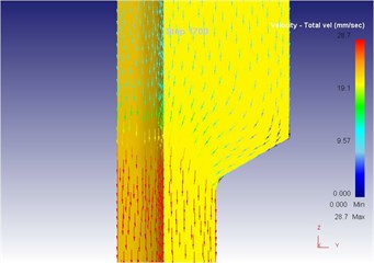
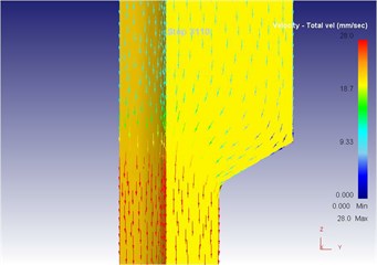
When the extrusion rod started to move, the material started to flow. When all the materials flowed out from the concave die (extrusion stroke is 10 mm), meanwhile a steady extrusion state was established, and the material flow reached a critical value, as shown in Fig. 15. Process from this moment to the extrusion stroke of 40 mm belonged to a steady extrusion process, where metal flow was steady, and tension fracturing did not take place, as shown in Fig. 16-Fig. 18. During metal plastic molding for the traditional extrusion, the metal blank in the die cavity fully touched the punching pin. Under effects of the punching pin, the internal metal flow speed and directions of metal flow lines changed continuously.
Fig. 14The extrusion stroke is 5 mm under the traditional extrusion
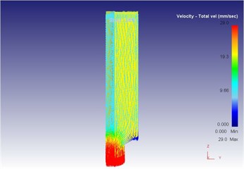
a) Overall flow velocity
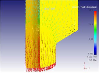
b) Local flow velocity
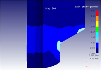
c) Equivalent strain
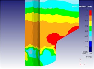
d) Equivalent stress
Fig. 15The extrusion stroke is 10 mm under the traditional extrusion
a) Overall flow velocity
b) Local flow velocity
c) Equivalent strain
d) Equivalent stress
Fig. 16The extrusion stroke is 17 mm under the traditional extrusion
a) Overall flow velocity
b) Local flow velocity
c) Equivalent strain
d) Equivalent stress
Fig. 17The extrusion stroke is 31 mm under the traditional extrusion
a) Overall flow velocity

b) Local flow velocity
c) Equivalent strain
d) Equivalent stress
At the initial stage of metal blank molding, because of shape features of the die, the metal blank flowed downwards under the extrusion force, filled the step of the convex die at first and the metal mainly flowed downwards at this moment; after the metal blank filled the small step of the lower convex die, one part of the metal material flowed upwards to fill the small step of the upper convex die and one part followed down towards the mold opening direction because the upper convex die of the mold also had a small step and it was smaller than the lower mold opening, and the resistance generated when the metal flowed upwards to fill the upper convex die was smaller than that generated when it flowed towards the mold opening according to the minimum resistance law. However, the metal mainly flowed upwards for filling as well at this moment, wherein the maximum metal flowing speed of 28.8 mm/s appeared at the contact position between punching pin and metal blank; after filling of the small step of the upper convex die, the metal blank went on flowing towards the mold opening under effects of the extrusion force of punching pin, and the maximum metal flowing speed of 30.3 mm/s appeared at the mold opening because the mold opening area was much smaller than that of the concave die cavity.
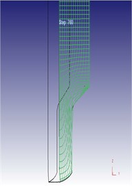
After applying vibration signals into the cold-extrusion plastic molding of metal, power sources promoting metal flow not only include the extrusion force from punching pin, but also include the vibration of concave die. Compared with the traditional extrusion, the metal flow speed and the metal flow line direction changed obviously after applying vibration. During simulation, Deform-3D software will re-divide the grids, so that extrusion strokes obtained in the simulation results are not as accurate as the extrusion stroke values obtained under the traditional extrusion, where only approachable values can be obtained. As can be seen from Fig. 19 to Fig. 23, three-dimensional metal flow line, equivalent strains and equivalent stress of the blank in different extrusion strokes after applying vibration signals are presented.
Fig. 18The extrusion stroke is 40 mm under the traditional extrusion

a) Overall flow velocity
b) Local flow velocity
c) Equivalent strain
d) Equivalent stress
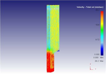
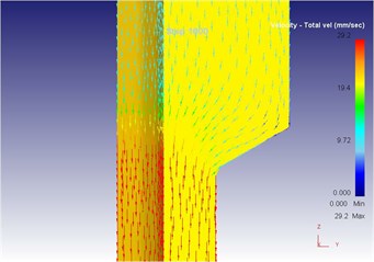
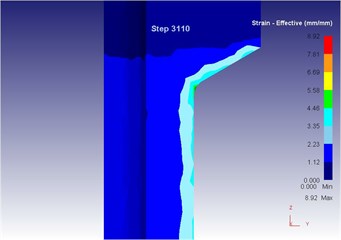
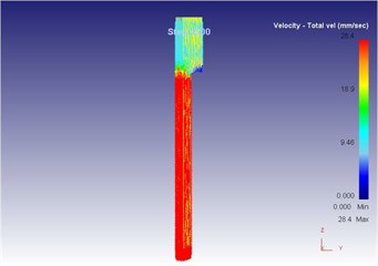
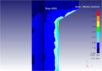
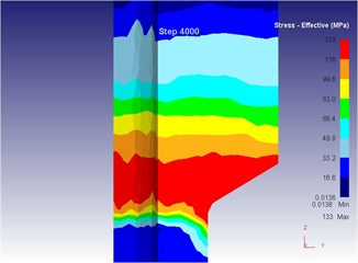
As can be seen from Fig. 19 to Fig. 23, we can find: under the vibration extrusion technology, when the extrusion stoke is 5 mm, the maximum speed of blank is 28.6 mm/s, the maximum equivalent strain is 3.19, and the maximum equivalent stress is 127 MPa. When the extrusion stoke is 10 mm, the maximum speed of blank is 29.2 mm/s, the maximum equivalent strain is 6.12, and the maximum equivalent stress is 131 MPa. When the extrusion stoke is 17 mm, the maximum speed of blank is 28.7 mm/s, the maximum equivalent strain is 9.89, and the maximum equivalent stress is 131 MPa. When the extrusion stoke is 31mm, the maximum speed of blank is 28.0 mm/s, the maximum equivalent strain is 8.92, and the maximum equivalent stress is 132 MPa. When the extrusion stoke is 40 mm, the maximum speed of blank is 28.4 mm/s, the maximum equivalent strain is 9.53, and the maximum equivalent stress is 133 MPa. When the extrusion rod started to move, the material started to flow. When all the materials flowed out from the concave die (extrusion stroke is 10 mm), meanwhile a steady extrusion state was established, and the material flow reached a critical value, as shown in Fig. 20. Process from this moment to the extrusion stroke of 40 mm belonged to a steady extrusion process, where metal flow was steady, and tension fracturing did not take place, as shown in Fig. 21-Fig. 23.
Fig. 19The extrusion stroke is 5 mm under the vibration extrusion
a) Overall flow velocity
b) Local flow velocity
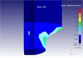
c) Equivalent strain
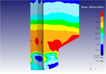
d) Equivalent stress
Fig. 20The extrusion stroke is 10 mm under the vibration extrusion
a) Overall flow velocity
b) Local flow velocity
c) Equivalent strain
d) Equivalent stress
Fig. 21The extrusion stroke is 17 mm under the vibration extrusion
a) Overall flow velocity
b) Local flow velocity
c) Equivalent strain
d) Equivalent stress
Fig. 22The extrusion stroke is 31 mm under the vibration extrusion
a) Overall flow velocity
b) Local flow velocity
c) Equivalent strain

d) Equivalent stress
Compared with three-dimensional metal flow of the blank in different extrusion strokes under the traditional extrusion (Fig. 14 to Fig. 18), after applying vibration, the metal blank was influenced by both the extrusion force and the concave die vibration. From Fig. 19 to Fig. 23, we can find that during metal molding, the metal plastic deformation was violent; the average metal flow speed was quicker than that under the traditional extrusion. In two kinds of extrusions, the metal flow lines were continuous and had no draining, eddy and flow breaking. Due to applying vibration signals, metal flow lines at corners of the concave die were changed, namely metal flow was improved. From the strain perspective, we can find that the strain was larger at two corners under applying vibration signals compared with the traditional technology. From the stress perspective, we can find that metal flow became easier and would then lead to decrease of the extrusion force.
Fig. 23The extrusion stroke is 40 mm under the vibration extrusion
a) Overall flow velocity

b) Local flow velocity
c) Equivalent strain
d) Equivalent stress
5.3. Influences of vibration on cross-sectional flow lines of metal
The number of grids in Flow Net can be set in Deform-3D. Two-dimensional flow lines can be observed according to changes of coordinate grid lines in metal plastic molding. In the paper, the number of grids was 15.
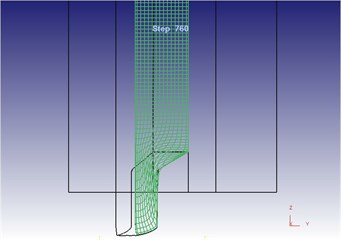
Fig. 24 shows the two-dimensional grid flow line after metal molding under the traditional extrusion. It is shown in the figure: horizontal grid lines were flattened under effects of extrusion force of the punching pin; longitudinal grid lines were bent to the mold opening under effects of extrusion force and die, indicating that the metal flowed towards the mold opening. This result is consistent with the metal flow directions in three-dimensional metal flow line under the traditional extrusion. Both the horizontal grid lines and the longitudinal grid lines were bent obviously at the mold opening corners, and grid lines close to the concave die surface were flattened and bent, so that the grid lines could not be distinguished. This is because that during metal flow, metal flow at the middle part of blank was lagged by the metal flow close to the concave die surface.
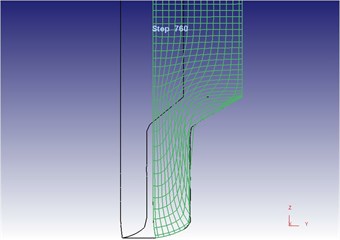
In Deform-3D, grid flow lines of the blank with applying vibration excitation were set by the same method, as shown in Fig. 25. In this figure, horizontal grid lines were flattened under effects of both the extrusion force of punching pin and the concave die vibration; longitudinal grid lines were bent towards the mold opening. This result is consistent with the metal flow directions in the metal flow speed figure under the vibration extrusion. Horizontal grid flow lines and longitudinal grid flow lines were bent obviously at corners; and near the corners, the grid flow lines at the contact parts between the blank and concave die inner wall were extruded compactly.
Fig. 24Two-dimensional grid flow line after metal molding under the traditional extrusion
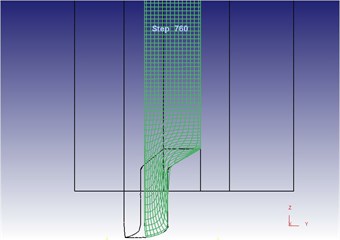
a) Overall flow line
b) Local flow line
Fig. 25Two-dimensional grid flow line after metal molding under the vibration extrusion
a) Overall flow line
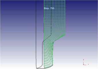
b) Local flow line
Under the vibration extrusion, grid flow lines were quite different from those under the traditional extrusion. As a whole, the bending degree of grid flow lines under applying concave die vibration was smaller than that under the traditional extrusion. Visually, the density of grid flow lines under the vibration extrusion was smaller than the density under the traditional extrusion. After applying vibration signal technology, grid flow lines at two corners became dense and suffered from obvious bending. It is proved in the result that applying vibration signals was beneficial for metal flow, indicating that vibration promoted metal flow and improved metal deformation uniformity of each part of blank during the plastic molding.
6. Conclusions
With the thick-wall cylinder as the researched object, the paper adopted the Deform-3D software to establish a finite element model. Numerical simulation was conducted under the traditional extrusion and vibration extrusion respectively. Compared with experiments, correctness of the finite element model in this paper was verified. Based on the verified model, evolution process of metal flow lines and grid flow lines under two kinds of extrusion was further analyzed and compared. Relevant conclusions are obtained:
1) After applying vibration, plastic deformation of metal became more violent and flowing speed of metal increased. In two kinds of extrusion, the metal particle obeyed the minimum resistance law. All the metal flow lines were continuous and had no draining, eddy or flow breaking.
2) After applying vibration signals on the concave die, plastic deformation of metal because more violent, the resistance against metal flowing decreased, and the bending degree of cross-sectional grid flow lines under applying vibration signals decreased, indicating that vibration promoted metal and improved metal deformation uniformity of each part of blank during the plastic molding.
3) Numerical simulation model and experimental method in this paper will provide important theoretical and practical engineering values for effectively applying vibration in mechanical processing fields.
References
-
Jeong M. S., Lee S. K., Yun J. H., et al. Green manufacturing process for helical pinion gear using cold extrusion process. International Journal of Precision Engineering and Manufacturing, Vol. 14, Issue 6, 2013, p. 1007-1011.
-
Chen J., Guo Q., Zhao Z., et al. Structures and mechanical properties of PEEK/PEI/PES plastics alloys blent by extrusion molding used for cable insulating jacketing. Procedia Engineering, Vol. 36, 2012, p. 96-104.
-
Chen D. C., You C. S., Nian F. L., et al. Using the Taguchi method and finite element method to analyze a robust new design for titanium alloy prick hole extrusion. Procedia Engineering, Vol. 10, 2011, p. 82-87.
-
Fernando M., Fei W. H., Hull C. Cure simulation of large rubber components: a comparison of compression and extrusion molding. Rubber Chemistry and Technology, Vol. 85, Issue 4, 2012, p. 495-512.
-
Qamar S. Z. Shape complexity, metal flow, and dead metal zone in cold extrusion. Materials and Manufacturing Processes, Vol. 25, Issue 12, 2010, p. 1454-1461.
-
Deng T. S., Wang G. C., Xia C. L., Xu X. F. Defects analysis of composite extrusion for 6061 aluminum alloy. Hot Working Technology, Vol. 17, 2010, p. 92-94.
-
Dong H. B., Huang Y. X. Flow properties of 6061 aluminum alloy processed by equal channel angular extrusion. Transactions of Materials and Heat Treatment, Vol. 32, Issue 2, 2011, p. 70-74.
-
Syahrullail S., Kamitani S., Nakanishi K. Experimental evaluation of refined, bleached, and deodorized palm olein and palm stearin in cold extrusion of aluminum A1050. Tribology Transactions, Vol. 55, Issue 2, 2012, p. 199-209.
-
Kang D. H., Kim T. W. Mechanical behavior and microstructural evolution of commercially pure titanium in enhanced multi-pass equal channel angular pressing and cold extrusion. Materials and Design, Vol. 31, 2010, p. 54-60.
-
Hayashi M., Jin M., Thipprakmas S., et al. Simulation of ultrasonic-vibration drawing using the finite element method (FEM). Journal of Materials Processing Technology, Vol. 140, Issues 1-3, 2003, p. 30-35.
-
Mousavi S. A. A., Feizi H., Madoliat R. Investigations on the effects of ultrasonic vibrations in the extrusion process. Journal of Materials Processing Technology, Vols. 187-188, 2007, p. 657-661.
-
Rosochowska M., Rosochowski A. FE simulation of ultrasonic back extrusion. 10th Esaform Conference on Material Forming, Vol. 907, Issue 1, 2007, p. 564-569.
-
Mekaru H., Nakamura O., Maruyama O., Maeda R., Hattori T. Development of precision transfer technology of atmospheric hot embossing by ultrasonic vibration. Microsystem Technology, Vol. 13, 2007, p. 385-391.
-
Bunget C., Ngaile G. Influence of ultrasonic vibration on micro-extrusion. Ultrasonics, Vol. 51, Issue 5, 2011, p. 606-616.
-
Huang Z. H., Lucas M., Adams M. J. Influence of ultrasonics on upsetting of a model pastel. Ultrasonics, Vol. 40, 2002, p. 43-48.
-
Daud Y., Lucas M., Huang Z. Superimposed ultrasonic oscillations in compression tests of aluminum. Ultrasonics, Vol. 44, 2006, p. 511-515.
-
Maeno T., Osakada K., Mori K. Reduction of friction in compression of plates by load pulsation. International Journal of Machine Tools and Manufacture, Vol. 51, Issue 7, 2011, p. 612-617.
-
Liang Y. X., Li X. F., Zuo D. W., Huang X. L., Miao H. Experimental research on internal thread formation by cold extrusion based on low frequency vibration. Acta Aeronautica et Astronautica Sinica, Vol. 34, Issue 2, 2013, p. 442-449.
-
Siegert K., Ulmer J. Influencing the friction in metal forming processes by superimposing ultrasonic waves. CIRP Annals-Manufacturing Technology, Vol. 50, Issue 1, 2001, p. 195-200.
-
Ashida Y., Aoyama H. Press forming using ultrasonic vibration. Journal of Materials Processing Technology, Vol. 187, 2007, p. 118-122.
-
Li W. R., Ruan J., Ren Y., Bai J. P. Vibration waveform research on electro-hydraulic exciter of differential cylinder controlled by 2D valve. Transactions of the Chinese Society of Agricultural Machinery, Vol. 44, Issue 10, 2013, p. 266-271.
-
Ogawa N., Ohtani K., Nakamura I., et al. Development of core technology for 3-D 1200 tonne large shaking table. Proceedings of 12th World Conference on Earthquake Engineering, New Zealand, 2000, p. 2156.
-
Gao C. H., Ji J. B., Yan W. M., Li N. Developments of shaking table technology in china. China Civil Engineering Journal, Vol. 47, Issue 8, 2014, p. 9-17.
-
Liang Y. X., Li X. F., Zuo D. W., et al. Dynamic simulation for a vibration processing equipment of internal thread formed by cold extrusion based on low frequency vibration. Zhendong yu Chongji (Journal of Vibration and Shock), Vol. 31, Issue 22, 2012, p. 143-146.
-
Hung J. C., Huang C. C. Evaluation of friction in ultrasonic vibration-assisted press forging using double cup extrusion tests. International Journal of Precision Engineering and Manufacturing, Vol. 13, Issue 12, 2012, p. 2103-2108.
-
Agnew S. R., Mehrotra P., Lillo T. M., et al. Texture evolution of five wrought magnesium alloys during route A equal channel angular extrusion: experiments and simulations. Acta Materialia, Vol. 53, Issue 11, 2005, p. 3135-3146.
-
Hagenimana A., Ding X., Fang T. Evaluation of rice flour modified by extrusion cooking. Journal of Cereal Science, Vol. 43, Issue 1, 2006, p. 38-46.
-
Atia A. A., Donia A. M., Elwakeel K. Z. Adsorption behaviour of non-transition metal ions on a synthetic chelating resin bearing iminoacetate functions. Separation and purification technology, Vol. 43, Issue 1, 2005, p. 43-48.
-
Qin C. B., Wei M. L., Feng G. A. O., et al. Experimental study on density-wave instability of high pressure steam-water two-phase flow in U-type tube. Nuclear Power Engineering, Vol. 26, Issue 6, 2005, p. 559-562.
About this article

