Abstract
The power reflux hydraulic transmission system (PRHTS), which is a new continuously variable transmission system, is put forward to enhance the efficiency of the torque converter. This study shows that the basic structure and operating principle of the PRHTS. Because the six-cylindered diesel engine’s operation range is between 40 Hz and 150 Hz, resonance point of the PRHTS should not exist in resonance region of engine. In order to study the resonance characteristics of the PRHTS, the dynamic model of the PRHTS is established by merging the planetary gear train dynamic model and torque converter dynamic model. This study also researches the amplitude-frequency characteristic curves of the PRHTS with different speed ratio and the effect of the torsional stiffness and damping coefficient to the amplitude-frequency characteristic of the PRHTS. The simulation result shows that the resonance frequency of the PRHTS could be excluded from engine’s operation range and the amplitude will decrease by changing the torsional stiffness and damping coefficient of the coupling.
1. Introduction
In the last few decades, automatic transmission (AT) has gained widespread use in a large percentage of vehicles due to its easy drive-ability, torque amplifying and torsional damping characteristics [1]. In the torque converter, automatic transmission fluid (ATF) is media which transmits power, so automatic vehicle has the ability to de-couple the engine from wheels. Moreover, the engine can work in the best economic zone by AT’s continuously variable transmission. Meanwhile, the torque fluctuation of engine is attenuated by torsional damping characteristics of the torque converter, thereby AT can prolong service life of the engine and transmission. But the efficiency of torque converter is lower than gears due to twice energy conversion in the torque converter. The overall transmission efficiencies of manual transmission and AT are 96.7 % and 86.7 %, respectively [2]. Therefore, improving the efficiency of AT has the vital significance. At present, the automatic vehicle improves the efficiency of the torque converter by the lock-up clutch system [3]. When the lock-up clutch is engaged, the engine connects with transmission directly, thus the efficiency of AT will be enhanced. Meanwhile, torsional vibration of automatic vehicle will be serious and comfortableness will be worse, because there is no torsional damping of torque converter between the engine and transmission system [4]. For the construction vehicle (such as wheel loader), torque converter usually has not the lock-up clutch, because the construction vehicle’s work condition is very terrible and external load is constantly changing. This paper presents the power reflux hydraulic transmission system (PRHTS), which is a new continuous variable transmission system, to improve the fuel economy and enhance the efficiency [5].
When the PRHTS is used in construction vehicle which has a six-cylindered diesel engine, the engine’s operation range is between 40 Hz and 150 Hz (800-3,000 rpm) [4], so the resonance frequency of the PRHTS should not exist in resonance region of engine. It is a complex issue to calculate the amplitude-frequency characteristic of the PRHTS, because there are two power flow in the PRHTS and the PRHTS both has the planetary gear train’s rigid transmission and the torque converter’s flexible transmission. In order to study the amplitude-frequency characteristic of the PRHTS, the dynamic model of the PRHTS is established by proposing the dynamic models of the planetary gear train and torque converter. At present, there are two dynamic models of the torque converter. For studying the influence of the two dynamic models of the torque converter to simulation result of the PRHTS’s amplitude-frequency characteristic, this paper establishes two dynamic models of the PRHTS by using two dynamic models of the torque converter, then the amplitude-frequency characteristic of the PRHTS is calculated. The amplitude-frequency characteristic of the PRHTS with different speed ratio is studied by simulation, and the effect of the torsional stiffness and damping coefficient to the amplitude-frequency characteristic of the PRHTS is studied, respectively.
2. The basic structure and operating principle of the PRHTS
For the low efficiency variator (such as CVT, hydraulics and hydro-dynamics), their efficiency can be enhanced by using the power reflux transmission [6-9]. Because the system’s input power of the power reflux transmission will be divided into two part power to transmit. One part of the input power transmits by the high efficiency gears, the other part of the input power transmits by the low efficiency variator. Thus, the power which transmits by the variator will decrease. Therefore, the efficiency can be enhanced by using the power reflux transmission.
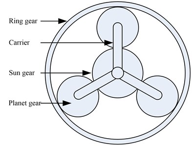
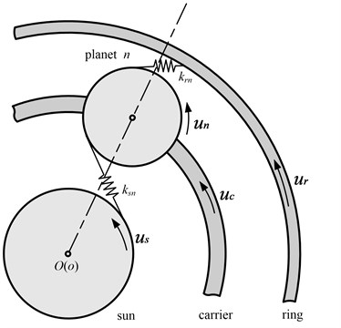
The PRHTS consists of a planetary gear train and a variator, wherein the variators have many types (such as mechanical, electric and hydraulic) [10]. The torque converter which has excellent shock absorption and cushioning is elected as the variator of the PRHTS. The other important component unit of the PRHTS is the planetary gear train. Planetary gear train consists of sun gear, ring gear, planet gears and carrier as shown in Fig. 1. The planetary gear train is commonly used by locking one component of sun gear, ring gear and carrier. Then the other two component motion, and one of those is used as the input shaft and the other is used as the output shaft. However, the planetary gear train of the PRHTS has two degrees of freedom, and the planetary gear train is used as the coupling device. The rotational speed of third moving component is depended on the rotational speed of other two moving components in the planetary gear train.
Fig. 1Structure diagram of the planetary gear train
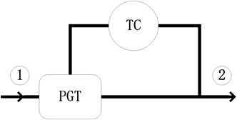
According to the location of the planetary gear train, the power reflux transmission has two basic structures. The power reflux transmission is called as the input coupled (IC) system when the planetary gear train locates at output shaft as shown in Fig. 2. The power reflux transmission is called as the output coupled (OC) system when the planetary gear train locates at input shaft as shown in Fig. 3. The simulation result shows that the efficiency of input coupled is higher than output coupled [11]. So, the input coupled is used in the PRHTS.
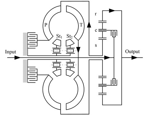
Fig. 4 shows the schematic of the PRHTS. A major characteristic of the PRHTS is the torque converter which anti-places the reflux power path, namely, the turbine of the torque converter connects with the input shaft of the transmission system and the pump of the torque converter connects with the sun gear of the planetary gear train. In the PRHTS another characteristic is the torque converter which has two stators. The prominent characteristic of the double stator torque converter is the wide high efficient range which efficiency is more than 80 %, because the working condition of the double stator torque converter consists of two converter conditions and a coupling condition. It can amplify transmission ratio range of the PRHTS in high efficient range by using the double stator torque converter.
Fig. 2Schematic picture of the Input Coupled. Arrows show the direction of the power flow. TC: torque converter; PGT: planetary gear train; 1: input shaft; 2: output shaft
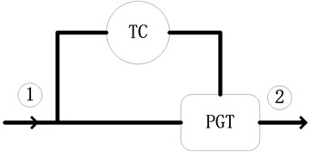
Fig. 3Schematic picture of the Output Coupled. Arrows show the direction of the power flow. TC: torque converter; PGT: planetary gear train; 1: input shaft; 2: output shaft
The power flow of the PRHTS is shown in Fig. 4 and is described as follows. First, the power of the engine enters the input shaft of the PRHTS (at the left side of Fig. 4). The power is then transferred into the carrier of the planetary gear train. Most of the power is transmitted into the ring gear (at the right side of Fig. 4), which is the power split characteristics of the planetary gear train. The remainder of the power, called reflux power, enters into the pump of the torque converter by the sun gear. Then, the reflux power goes into the input shaft of the PRHTS by torque amplification of the torque converter. The reflux power joins with the output power of engine, and both enter into the carrier. Because of the special reflux power characteristics, the PRHTS has a continuous variable ratio. In other words, the output shaft of the transmission system has a continuous variable speed by means of the torque converter, while the speed of the engine is constant. Therefore, the PRHTS is a continuous variable transmission system.
Fig. 4Schematic and power flow of the PRHTS. T: turbine; P: pump; St1, St2: stators; r: ring gear; c: carrier; s: sun gear
3. Dynamic modeling of the PRHTS
3.1. Dynamic modeling of the planetary gear train
Fig. 5 shows the dynamic modeling of the planetary gear train [12]. Anti-clockwise is assumed as the positive direction. Newton’s law is utilized to obtain the equations of motion of the planetary gear train, as follows:
among them:
Fig. 5The dynamic modeling of the planetary gear train
3.2. Dynamic modeling of the torque converter
The torque converter is a fluid dynamics element. At present, there are two dynamic models to describe the torque converter dynamic characteristics. One is the quasi-static model by using steady-state characteristics of the torque converter. The other one is the transient model by one-dimensional flow path theory.
3.2.1. Quasi-static model of the torque converter
The quasi-static model can describe the transient characteristics of the torque converter based on the 1-D look-up table of the torque converter characteristics. The fluid torque of pump and turbine will be obtained by using steady state torque ratio (turbine fluid torque divided by pump fluid torque) and steady state capacity data (pump speed divided by the square root of pump fluid torque). The acceleration of the pump and turbine can be calculated by the torque and moment of inertia of pump and turbine. The general framework for the quasi-static model is as follows:
where denotes the acceleration of the pump. denotes the acceleration of the turbine.
3.2.2. Transient model of the torque converter
An alternative method to simulating the torque converter is to use the transient model. The transient model is based upon the work published by Tobler [13]. The transient torque converter model consists of four energy first-order nonlinear differential equations to describe the dynamic characteristics of the torque converter in four state variables. The four state variables are the volumetric flow rate of the torque converter and the angular speed of the pump, turbine and stator, respectively. The inputs of the transient model are the pump torque and turbine torque. The three equations are the pump, turbine and stator inertias follow from the moment-of-momentum equation (Eqs. (11-13)). The fourth equations are conservation of energy equations of the torque converter (Eq. (14)). The four first-order nonlinear differential equations are represented as follows:
In the conservation of energy equations, which consists of the shock losses and the flow losses is the power loss of the torque converter:
3.2.3. The difference between the two dynamic modeling
According to Eqs. (11-12), the dynamic torque ratio and dynamic capacity of the torque converter can be obtained, as shown in Eqs. (18-19). The dynamic torque ratio and dynamic capacity may be divided into three parts. The first part is the steady state terms. The second part is the transient annular fluid terms which is directly proportional to the rate of volumetric flow rate. The third part is the transient inertia terms, namely, inertial force of the pump and turbine. When the torque converter is in a steady state condition, both second and third parts of Eqs. (18-19) are zero, only the first part is not zero. So, the first part represents the steady state torque ratio and steady state capacity. The third part is expressed by Eqs. (8-9) in the quasi-static model. Thus it can be seen that the difference between quasi-static model and transient model is the transient annular fluid terms.
The formulas of the quasi-static model are simple than the transient model, so the calculation of the quasi-static model is more easy. Moreover, the transient model needs many parameters of the torque converter, but the quasi-static model only needs the steady state torque ratio and steady state capacity data. Most of the transmission control units use the quasi-static model to control AT [14-17]. On the other hand, though the calculation of the transient model is complicated, the transient model contains the transient annular fluid terms. Therefore, the transient model can describe the transient characteristics of the torque converter more accurately. In a word, both the quasi-static model and the transient model have benefits:
3.3. Dynamic modeling of the PRHTS
Fig. 6 shows the dynamic model of the PRHTS. There is a coupling between the input shaft and the carrier. By merging the equilibrium equation of the planetary gear train dynamic and the torque converter dynamic, the equilibrium equation of the PRHTS dynamic is established.
4. Amplitude-frequency characteristic of the PRHTS
4.1. The amplitude-frequency characteristic of the PRHTS by using two dynamic models of the torque converter
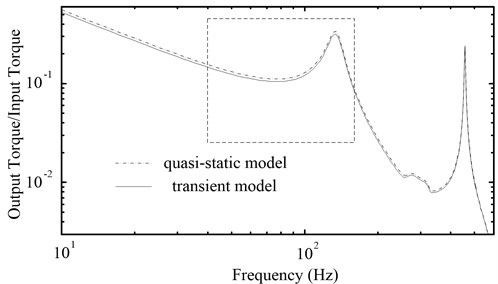
In order to study the influence of the two dynamic models of the torque converter to simulation result of the PRHTS’s amplitude-frequency characteristic, the dynamic models of the PRHTS are established by using the quasi-static model and the transient model, respectively. Then the amplitude-frequency characteristic curves of the PRHTS are obtained, as shown in Fig. 7. It is the engine’s operation range (40 Hz-150 Hz) in the dashed frame. It can be seen that the difference between the curves is so small. So, the effect of transient annular fluid terms to the amplitude-frequency characteristic of the PRHTS is minimal, which can be ignored. For ease of calculation, the quasi-static model is used to establish the dynamic model of the PRHTS.
Fig. 6The dynamic model of the PRHTS: kt denotes the torsional stiffness between the input shaft and the torque converter; kp denotes the torsional stiffness between the sun gear and the torque converter; Cd denotes the damping coefficient of the coupling; kd denotes the torsional stiffness of the coupling

Fig. 7The amplitude-frequency characteristic curves of the PRHTS by using two dynamic models of the torque converter
4.2. The amplitude-frequency characteristic of the PRHTS with different speed ratio
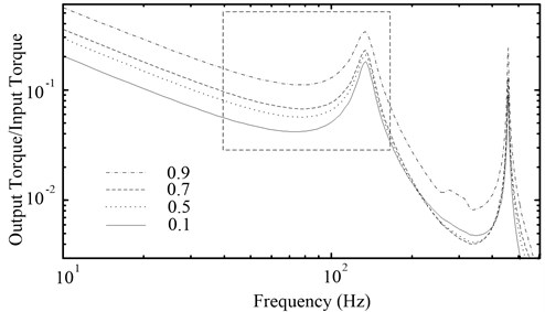
The PRHTS is a continuous variable transmission system, so its speed ratio range which likes the torque converter is zero to one. When the PRHTS is used in construction vehicle, the different speed ratio of the PRHTS will be applied. For this reason, it is essential to study the amplitude-frequency characteristic curves of the PRHTS with different speed ratio. When the speed ratio of the PRHTS is 0.1, 0.5, 0.7 and 0.9, Fig. 8 shows the amplitude-frequency characteristic curves. It can be seen that the speed ratio will not affect the resonance frequency of the PRHTS. But the amplitude increases with speed ratio in the engine’s operation range, which is the effect of the torque converter. It is validated that the amplitude of the torque converter increases with speed ratio [18]. So, the torsional damping of the PRHTS is better when the vehicle starts.
Because the resonance frequencies of the PRHTS with different speed ratio are same, studying a certain speed ratio is sufficient to represent the resonance frequency of the PRHTS. When the resonance frequency of the PRHTS with a certain speed ratio is excluded from engine’s operation range, the resonance frequency with all speed ratios are not in engine operation range.
Fig. 8The amplitude-frequency characteristic curves of the PRHTS with different speed ratio
4.3. Changing the amplitude-frequency characteristic of the PRHTS
According to the dynamic model of the PRHTS, amplitude-frequency characteristic curves can be obtained, as shown in Fig. 7. There is a resonance point in the engine’s operation range. In order to exclude the resonance point from engine’s operation range, the parameters of PRHTS components need to be changed. Because the PRHTS must match the engine, it should not change the transmission performance of the torque converter and the planetary gear train.
It has been studied that the effect of the torque converter parameters (such as flow area, pump radius, turbine radius, stator radius, pump blade angle, turbine blade angle and stator blade angle) to the steady state torque ratio and steady state capacity data, respectively [19]. It can be seen that the torque converter parameters are important to the transmission performance. Once a parameter of the torque converter is changed, the PRHTS will not match the engine. Therefore, the parameters of the torque converter should not change. In order to guarantee the transmission performance of the planetary gear train, its parameters also can’t change. Therefore, only the parameters of the coupling can be considered to change. It is studied the effect of the torsional stiffness and damping coefficient of the coupling to the PRHTS amplitude-frequency characteristic.
4.3.1. Changing the torsional stiffness of the coupling
For the mechanical system, the torsional stiffness is very important to the resonance frequency. Therefore, the torsional stiffness needs to be analyzed. Fig. 9 shows the amplitude-frequency characteristic curves of the PRHTS which the torsional stiffness of the coupling is 8×10⁴, 4×10⁵, 2×10⁶ and 1×10⁷ N·m·rad-1, respectively. In Fig. 9, it can be seen that the resonance frequency of the PRHTS increases with the torsional stiffness in engine’s operation range. When the torsional stiffness is less than 1×10⁵ N·m·rad-1 or greater than 1×10⁷ N·m·rad-1, the resonance frequency of the PRHTS will be excluded from engine’s operation range. In consideration of the torsional stiffness should not be too small, so the torsional stiffness of the coupling should be greater than 1×10⁷ N·m·rad-1.
4.3.2. Changing the damping coefficient of the coupling
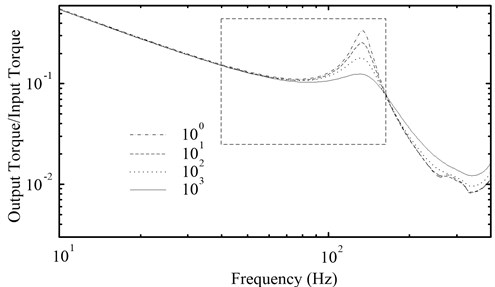
For the PRHTS, the damping coefficient of the coupling is another important parameter. Fig. 10 shows the amplitude-frequency characteristic curves of the PRHTS which the damping coefficient of the coupling is 100, 101, 102 and 103 N·m·s·rad-1, respectively. It can be seen that the resonance frequency of the PRHTS will not change while the damping coefficient changes. However, the amplitude of the resonance point decreases with the damping coefficient in engine’s operation range. This is due to the attenuation characteristic of damping. Therefore, the coupling should use a certain value damping.
Fig. 9The amplitude-frequency characteristic curves of the PRHTS with different torsional stiffness of the coupling
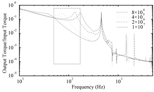
Fig. 10The amplitude-frequency characteristic curves of the PRHTS with different damping coefficient of the coupling
5. Conclusions
A new transmission scheme (PRHTS), which is a continuous variable transmission system, is introduced in this paper to improve the fuel economy of construction vehicle. It is analysed that the basic structure and operating principle of the PRHTS. The dynamic model of the PRHTS is established by proposing the dynamic models of the planetary gear train and torque converter. Then the main conclusions are:
1) The influence of the two dynamic models of the torque converter to the simulation result of the PRHTS’s amplitude-frequency characteristic is small. Therefore, the effect of transient annular fluid terms to the amplitude-frequency characteristic of the PRHTS is minimal, which can be ignored.
2) The simulation result shows that the speed ratio will not affect the resonance frequency of the PRHTS, but the amplitude increases with speed ratio in the engine’s operation range. Therefore, the torsional damping of the PRHTS is better when the vehicle starts.
3) The resonance frequency of the PRHTS increases with the torsional stiffness and the amplitude of the resonance point decreases with the damping coefficient in the engine’s operation range. In a word, the resonance frequency of the PRHTS could be excluded from engine operation range and the amplitude will decrease by changing the torsional stiffness and damping coefficient of the coupling.
References
-
Lee J.-H., Lee H. Dynamic simulation of nonlinear model-based observer for hydrodynamic torque converter system. SAE Technical Paper 2004-01-1228, 2004.
-
Kluger M. A., Long D. M. An overview of current automatic, manual and continuously variable transmission efficiencies and their projected future improvements. SAE International, 1999-01-1259, 1999.
-
Jang J. D., Lee I. T., Kim W. J., et al. Effect of a piston hole under the slip control condition of the lock-up clutch in a torque converter. International Journal of Automotive Technology, Vol. 16, Issue 1, 2015, p. 139-144.
-
Park T., Song J., Jang J., et al. Dynamic analysis of damper system in torque converter. SAE Technical Paper 2007-01-3749, 2007.
-
Wang H., Sun D., Qin D. A new continuously variable transmission system applied to transmission system of the roadheader’s cutting unit. Proceedings of the Institution of Mechanical Engineers Part C – Journal of Mechanical Engineering Science, Vol. 2016, DOI 10.1177/0954406216649404, 2016, (in Press).
-
Mantriota G. Power split continuously variable transmission systems with high efficiency. Proceedings of the Institution of Mechanical Engineers, Part D: Journal of Automobile Engineering, Vol. 215, Issue 3, 2001, p. 357-358.
-
Carl B., Ivantysynova M., Williams K. Comparison of operational characteristics in power split continuously variable transmissions. SAE International 2006-01-3468, 2006.
-
Bottiglione F., Mantriota G. MG-IVT: an infinitely variable transmission with optimal power flows. Journal of Mechanical Design, Vol. 130, Issue 11, 2008, p. 112603.
-
Mantriota G. Infinitely variable transmissions with automatic regulation. Proceedings of the Institution of Mechanical Engineers, Part D: Journal of Automobile Engineering, Vol. 215, Issue 12, 2001, p. 1267-1280.
-
Linares P., Méndez V., Catalán H. Design parameters for continuously variable power-split transmissions using planetaries with 3 active shafts. Journal of Terramechanics, Vol. 47, Issue 5, 2010, p. 323-335.
-
Bottiglione F., Mantriota G. Reversibility of power-split transmissions. Journal of Mechanical Design, Vol. 133, Issue 8, 2011, p. 84503.
-
Lin J., Parker R. G. Analytical characterization of the unique properties of planetary gear free vibration. Journal of Vibration and Acoustics – Transactions of the ASME, Vol. 121, Issue 3, 1999, p. 316-321.
-
Hrovat D., Tobler W. E. Bond graph modeling and computer-simulation of automotive torque converters. Journal of the Franklin Institute-Engineering and Applied Mathematics, Vol. 319, Issues 1-2, 1985, p. 93-114.
-
Janarthanan B., Padmanabhan C., Sujatha C. Longitudinal dynamics of a tracked vehicle: simulation and experiment. Journal of Terramechanics, Vol. 49, Issue 2, 2012, p. 63-72.
-
Liu Z., Gao J., Zheng Q. Antishudder gearshift controller design for automatic transmission. IEEE Transactions on Vehicular Technology, Vol. 60, Issue 9, 2011, p. 4261-4275.
-
Zhang Y., Zou Z., Chen X., et al. Simulation and analysis of transmission shift dynamics. International Journal of Vehicle Design, Vol. 32, Issues 3-4, 2003, p. 273-289.
-
Kim D. H., Yang K. J., Hong K. S., et al. Smooth shift control of automatic transmissions using a robust adaptive scheme with intelligent supervision. International Journal of Vehicle Design, Vol. 32, Issues 3-4, 2003, p. 250-272.
-
Pohl B. Transient torque converter performance, testing, simulation and reverse engineering. SAE Technical Paper 2003-01-0249, 2003.
-
Adibi Asl H., Lashgarian Azad N., Mcphee J. Math-based modeling and parametric sensitivity analysis of torque converter performance characteristics. SAE Technical Paper 2011-01-0732, 2011.
About this article

The authors would like to acknowledge the support and contribution from the State Key Lab of Mechanical Transmission, Chongqing University, China. This research was funded by the National Natural Science Foundation of China (Grant No. 51375505) and the National Basic Research Program of China (973 Program, Grant No. 2014CB046304).
