Abstract
Lubrication on sharp curves has been commonly adopted as a method of reducing friction between the wheel flange and rail gauge face to minimize wear and energy consumption. Additionally, lubrication between the running surface of the low-rail and the wheel tread has recently been recognized as a significant factor in reducing the likelihood of low-rail corrugation, squealing noise and rail gauge face wear. This paper describes a friction-moderating system (FRIMOS) for the interface between the top of the low-rail and the wheel tread, consisting of a solid lubricant known as a friction moderator and a jetting device installed on the vehicle to apply the moderator to the wheel/rail interface.
1. Introduction
At the movement of wheel couples on curves working surfaces of the head of an external rail are exposed to the strengthened influence of rolling stock and receiving the corresponding deformations, are work in a form of bandages of wheel couples [1]. It leads to that emergence of damages and their development, and also intensity of wear of rails in curves approximately in 3, 4 times is more, than on direct sites of the way [2]. Dynamic interaction of wheel and rail and effect connected with it remain still actual for railway transport. The existence of side wear on an internal surface of rail head makes negative impact on dynamics of interaction of rolling stock and way, and also causes not small economic damage to the railroad in general [3]. The concept and explanation of side wear effect requires a clear idea of the processes proceeding in the zone of contact of wheel and rail. Intensive side wear is possible at creation of certain conditions. One of them is emergence of plastic deformation in the contact zone of wheel with rail, assessment criterion which the level of contact tension is. In the conditions of contact interaction of wheel and rail in the contact zone there is tension and elastic plastic deformations which are one of the defining revolting factors to formation of the compelled fluctuations. It is well known that the fluctuations which are generated in a tribosystem effectively influence destruction of materials therefore studying of the fluctuations arising at friction, and their influence on destruction of materials is extremely important task in tribology [4]. Besides, in the conditions of repeated loading, division of material particles as a result of accumulation of contact fatigue damages to near-surface layers of the interacting bodies is possible. Tension in the contact zone of wheel and rail has essential value for their durability [5]. Forces of adhesion between wheel and rail depend on this tension. Engagement of wheels with rails at the movement of crews is followed by constant wheel slip under the influence of various factors which realize their work at full stretch programmed by the design of the interacting elements. So, even at free rolling rails and wheels of an initial profile are in advance doomed to wear [6, 7].
2. Materials and methods
Wheels on one axis have a multidirectional conic profile, the center of rolling of conic surface on the plane is the cone top, each wheel has its own top, all points of the contact plane have to describe circles with radius equal to distance to the top. Circles of different diameter of contact zone of each wheel on forming a cone there is a compelled slipping caused by taper. Frictional interaction in curve increases resistance force to the movement arising at impact of crew on an internal wheel, working in the coupling mode, which makes rotate slowed down by slipping external wheel. Existence of curve small radiuses leads to emergence of cross dynamic forces which have special impact on wear and stability of the movement in the rail track. For example, at the movement in the curve the center of crew gravity is affected by centrifugal force in Fig. 1.
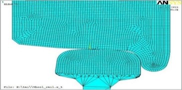
Fig. 1Geometrical final and element models of contact of wheel and rail for new a) and run in b) profiles
a)
b)
where, the mass of crew; movement speed.
Limited compensation of centrifugal force in curve sites of the way can be reached an eminence of of an external rail which reduces action of centrifugal force by the size of a horizontal component from crew weight.
Foreign experience of researchers of various conditions of a way making observations on influence on intensity of side wear of external rails is given by the major factors influencing intensity of side wear: track width; can’t outstanding acceleration.
Influence of track width in curve on intensity of side wear, is visually presented on graphics. Proceeding, from the schedule it is offered to enter the following parameters of width of a track: 1524 mm in curves, which radius of 400 m 600 m; 1530 mm, then 400 350 m and 1535 mm; then 350 m. Now on the main lines of JSC there is a problem of the increased side wear of rails which nature is explained by condition of the way which are given on schedules below. Proceeding, from a graphic representation of Fig. 2, follows that 85 % of curve sites of way with a radius of 1200 m and less don’t correspond on an eminence of an external rail. It in turn influences increase in cross forces in contact zone flange wheel and rail head which we can see. All these above-stated derogations from norms are reflected in discrepancy of curve sites of way, on the allowed movement speeds which is graphically represented. The main attention should be paid to cross (frame) forces which reach considerable size at the movement of cargo rolling stock. The size of frame force is directly proportional to crew weight. Prevention of way deformation is possible due to restriction of cross force with the admissible standard for a rolling stock of the maximum weight. The side wear of an internal edge of rail head connected with interaction of running gears of a rolling stock and top structure of a way considerably increases operational costs by the current contents not only ways, but also rolling stock. Emergence of intensive side wears is possible under certain conditions [8]. One of them is emergence in the contact zone of wheel with rail of plastic deformation as which the level of contact tension is served with assessment criterion. It defines character of the intense deformed state (elastic, plastic) the contacting materials, and also has impact, in particular, on intensity of their wear and coefficient of coupling between them. Experimental determination of contact tension in wheel – rail system at modern development of metrology is almost impossible. Therefore, it is necessary to use only calculation methods. Classical methods of calculation of contact tension for two adjoining bodies with curvilinear surfaces without taking note of friction forces are based on the common decision received by G. Gerts and developed in the subsequent by other scientists. In particular, N. M. Belyaev applied G. Gerts’s theory to determination of superficial and deep contact tension between wheel and rail taking into account the form of their spot of contact changing under the influence of wear [9].
Contact of not worn-out profiles of rail and wheel, neglecting taper of the last, it is possible to consider, as a contact of two elastic cylinders with mutually perpendicular axes. Cylinders have the general normal in the contact point (conveniently to combine axis with it), along which the squeezing force , and also the general tangent plane in which axes and lie is directed. Thus the elliptic platform of contact is formed. The big half shaft of a (directed along rail head and small half shaft of of this platform are determined by formulas:
where, , coefficients; Poisson’s coefficient; elasticity module; , radiuses according to wheel and rail.
The tension on contact platform reaching the greatest value in its center and coinciding in the direction with the maximum normal tension on an axis is defined by expression:
where contact area.
The spatial distribution diagram of tension on the platform of contact is limited to an ellipsoid surface. Tension in any point of this platform:
The most effective and exact means of research of the intense deformed state (IDS) in the contact zone flange wheels with an internal edge of rail head taking into account materials and geometry of the contacting bodies, way of the application of loadings, boundary conditions and some other factors is mathematical modeling by method of final elements. By means of complex of final and element modeling of ANSYS used for the solution of problems of mechanics of a deformable solid body was carried out assessment of the volume VAT of materials of wheel and rail in the contact zone. Calculation was carried out both for new, and for the earned extra profiles of an locomotive wheel with a diameter of 1250 mm and rail of P65 at decreases and increases in friction forces in the contact zone and change of vertical and horizontal cross loads from wheel of rail in the range of 70-120 kN. The received geometrical final and element models of contact for the new and run in extra profiles are presented in Fig. 1.
It is known that materials of wheel and rail in the conditions of volume tension near the center of an elliptic platform of contact experience comprehensive compression at which they can maintain quite high tension. According to the theory of durability Mora, at volume tension of the contacting materials the greatest tangent tension in contact points, equal semi-differences between the greatest and smallest main tension is dangerous. At the chosen system of coordinates for point in the center of an ellipse of pressure normal tension , , is the main tension respectively , , . Taking into account it for each of the contacting bodies in the existing systems wheel rail at small coefficient of friction is dangerous in the stopping regime two areas.
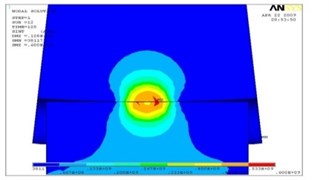
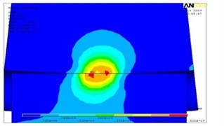
The first is located on the surface of an internal cove of rail head (see Fig. 2(a)), i.e. on the surface of contact of a crest of a wheel with rail head (superficial contact tension), and the second is in each of the interacting bodies (see Fig. 2(b)) in the areas located at a certain depth (deep contact tension). In process there is wear of contacting surfaces. The form of contact platform changes from point-to-point to single-point (mutually earned extra). At the maximum wear of profiles of wheel and rail, in the stopping regime are the most dangerous areas in the center of a rectangular platform of contact (see Fig. 3(a)) (superficial contact tension), and also in the adjoining bodies (see Fig. 3(b)) along the normal passing through the center of a zone of contact (deep contact tension) [7].
Fig. 2Areas with the greatest tangent tension (red zones) for new profiles of wheel and rail

a) On a contact surface
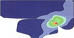
b) In the interacting bodies
Fig. 3Areas with the greatest tangent tension (red zones) for worn-out profiles of wheel and rail
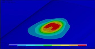
a) On a contact surface

b) In the interacting bodies
At increase of friction coefficient, as a result of the application of the traction or brake moment, in the contact zone the crest of wheel and an internal edge of rail head l, in total with normal, work tangential forces which change distribution of tension to contact surfaces, in the interacting bodies and near a contour of a contact platform (see Fig. 4). Thus, the arrangement and sizes of the maximum tangent tension, and also a ratio between superficial and deep contact tension change. Tangential forces increase the stretching tension on a lobby by contact surfaces (in the direction of action of forces) parts of contour of contact platform and reduce them on the back. At calculation by method of final elements the assessment of tension was carried out on the greatest normal tension and on condition of plasticity (fluidity) of Mises-Genka according to expression:
where, fluidity tension.
3. Results and discussion
Results of calculation are presented in Figs. 1-4. In Fig. 1 dependences of the maximum normal tension in contact zone of horizontal (cross) load from wheel of rail for new profiles of wheel and rail are shown at run out (coefficient of friction of 0,01) and in the mode of draft or braking (coefficient of friction of 0,3), and also dependences of tension for the earned extra profiles of the contacting bodies at run out.
Fig. 4The intense deformed condition of a zone of contact a) at run out and b) at increases friction forces on contact platform
a)
b)
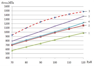
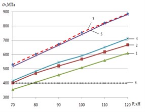
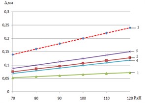
Fig. 5a) Maximum normal tension; b) equivalent tension according to Mises-Genka; c) elastic plastic deformations of an internal edge of rail head: 1 – run in extra profile of wheel of an electric locomotive and rail f= 0.01; 2 – new profile of wheel of an electric locomotive and rail f= 0.01; 3 – new profile of wheel of an electric locomotive and rail f= 0.3; 4 – worn-out profile of rail car wheel and rail; 5 – new profile of rail car wheel
a)
b)
c)
In Fig. 2 similar dependences of equivalent tension (fluidity tension) on Mises-Genka’s condition, and are given in Fig. 5(c) – elastic plastic deformations in the field of contact. The analysis of the presented dependences shows that for new profiles the increase in coefficient of friction on contact platform caused by transfer of the traction (brake) moments increases in comparison with stopping regime ( 0,01) the maximum normal tension on average for 9 %, fluidity tension for 19 %, and elastic plastic deformations – for 85 %. At operation there is wear (extra earnings) of the contacting surfaces, the area of contact increases therefore the contact tension and deformations decrease. As cross load from wheel of rail for passenger and cargo electric locomotives is in range of 90-125 kN, and the fluidity limit for steel modern rails of P65 makes about 400 MPa, on an internal edge of rail head there are plastic deformations which are one of necessary conditions of intensive wear. The greatest tension on plasticity condition (see Fig. 5(a)) arises at contact of new profiles of carriage wheels and rails (curve 5), and also new profiles of wheels of electric locomotives with new rails at increases in contact of friction force ( 0,3) arising at the movement in the traction mode (curve 3). In this mode equivalent tension in the contact zone for new profiles of wheels of electric locomotives and rails increases, in comparison with stopping regime, on average on 30 %.
Therefore, the most adverse conditions of interaction of rolling stock and way on criterion of contact tension and, as a result, the created conditions for intensive side wear and origin of defects of contact and fatigue character develop in an initial stage mutual extra earnings of new profiles of wheels and rails. It is especially actual for wheels of freight cars at which loads of wheel can reach 120 kN, that is equal locomotive, but with a smaller diameter.
In operational process new profiles are worn out, earned extrun in, change in a form and size of contact zone that leads to decrease in tension (see Fig. 5(a), 5(b)) and elastic plastic deformations in contact (see Fig. 3). However, contact tension on plasticity condition (see Fig. 5(b)) for using on the domestic railroads rolling stock exceeds a limit of fluidity of rail steel that creates one of necessary conditions for intensive side wear of rails.
4. Conclusions
For the purpose of reduction of side wear of rails, crests of wheel couples, and also reduction of wagging it is necessary to refuse point-to-point contact of the wheel with rail applied in our country as it is one of the main reasons for damages of wheel couples and rails. It is necessary to develop new conformal (coordinated) profile of surfaces of driving of wheel and rail.
Development and implementation of conformal profiles will allow:
1. As much as possible to raise resource of operating time of rails and wheel couples due to uniform wear of the interacting profiles of wheel and rail, and also reduction of defects of contact and fatigue character, thanks to decrease in wheel slip on rail;
2. Increase in smoothness of the course of rolling stock due to reduction of wagging of carriage carts;
3. To reduce risk of descent of rolling stock in curve sites of way;
4. To reduce fuel and energy costs of hauling operation;
5. To reduce growth of malfunctions of way and rolling stock owing to decrease in cross loads on them.
Following the results of realization it is possible to achieve economy of operational costs of the company on the maintenance of infrastructure from 5 to 10 %.
References
-
Eadie D. T., Kalousek J., Chiddik K. C. The role of high positive friction (HPF) modifier in the control of short pitch corrugations and related phenomena. Wear, Vol. 253, 2002, p. 185-192.
-
Ishida M. Noise and vibration due to rail corrugations. Tribologists, Vol. 48, 2003, p. 23-29.
-
Ohno K., Ban T., Obara T. Improvement of adhesion between wheel and rail by ceramics particle injection. Tribologists, Vol. 41, 1996, p. 973-978.
-
Gupta V., Hahn G. T., Bastias P. C., Rubin C. A. Calculations of the frictional heating of a locomotive wheel attending rolling plus sliding. Wear, Vol. 191, 1996, p. 237-241.
-
Cameron A., Gordon A. N., Symm G. T. Contact temperatures in rolling/sliding surfaces. Proceedings of the Royal Society A, Vol. 286, 1965, p. 45-61.
-
Fischer F. D., Werner E., Knothe K. The surface temperature of a halfplane heated by friction and cooled by convection. Journal of Applied Mathematics and Mechanics, Vol. 81, 2001, p. 75-81.
-
Bucher F., Theiler A., Knothe K. Normal and tangential contact problem of surfaces with measured roughness. Wear, Vol. 253, 2002, p. 206-220.
-
Tomeoka M., Kabe N., Tanimoto M., Miyauchi E., Nakata M. Friction control between wheel and rail by means of on-board lubrication. Wear, Vol. 253, 2002, p. 124-129.
-
Ishida M., Ban T., Aoki F. Effect of lubrication on vehicle/track interaction and performance of friction moderator. Proceedings of World Congress on Railway Research, Montreal, Canada, 2006.
-
Ishida M., Ban T., Iida K., Ishida H., Aoki F. Effect of moderating friction of wheel/rail interface on vehicle/track dynamic behavior. Proceedings of 7th International Conference on Contact Mechanics and Wear of Rail/Wheel Systems, Brisbane, Australia, 2006, p. 227-233.
About this article

