Abstract
The paper studies the behaviors of synthetic jets under the excitation of cavity resonance which is produced by an isolated two-dimensional actuator. A cross hot-wire was used to obtain measurements within the velocity field. This research revealed a number of notable phenomena, such as the appearance of vortex pairs only in the vicinity of orifice exit as well as their rapid dissipation downstream. Our results of analysis of the plane velocities of the synthetic jets indicate that effective flow control can be achieved only in regions close to the orifice. It is interesting to note that a linear relationship could be obtained only by taking the logarithm of mean velocity () as well as downstream distance () in different transverses, and by using a curve fitting then linear relations can be obtained. The slopes of synthetic jets under excitation of cavity resonance were between –7/10 and –3/5, which represents a sine wave of 160 Hz on 15 V. The original time-domain data was then converted using fast Fourier transform to the show power spectrum in order to reveal more about the flow behavior of synthetic jets. Characteristic frequencies were identified at 80 Hz and 160 Hz in the initial center of the orifice. The former frequency (80 Hz) can be attributed to the collision of the upper vortex and lower vortex of the synthetic jet. The latter frequency (160 Hz) refers to the excitation frequency of the signal source. Following the development of the synthetic jet, the excitation frequency of 160 Hz eventually disappeared downstream but the characteristic frequency of 80 Hz remained until 8. These experimental results make a valuable contribution to the further development of flow control in the future.
1. Introduction
Numerous studies have addressed the issue of flow control involving passive or active control. Passive control techniques include turbulators [1] and vortex generators [2], which are used to change the geometric shape of the device itself in order to adjust the pressure gradient on the surface with the aim of reducing drag in flow control. Active control techniques require that variations in flow and characteristics of the actuator be taken into consideration in order to achieve the desired flow control through artificial measures. Synthetic jet actuators (SJAs) are considered an active flow control device. A synthetic jet actuator is basically composed of an orifice (or a slot), a cavity and an excitation mechanism, which can be classified into three types (including an oscillating diaphragm [3], a piston-in-cylinder arrangement [4] and acoustic excitation [5, 6]). A synthetic jet actuator produces continuous synthetic jests at the edge of an orifice by periodic motion of a membrane compact mounted on the external surface of cavity. When the membrane of the excitation mechanism moves forward the orifice, a vortex pair occurs at the edge of the orifice. Inversely, the membrane of the excitation mechanism moves away from the orifice by its own self-induced velocity. One of important property of synthetic jet is a zero-net-mass-flux jet whereas it is a nonzero-momentum-flux jet [3, 7, 8]. Many researchers have investigated the application of SJAs in the cooling of electronics [9, 10], fluid mixing [11] and flow control [12-15]. These researchers were also interested in determining the optimal operating parameters for flow control using SJAs. A number of empirical studies on the fundamental characteristics of SJA have reported resonance frequencies and a wide range of excitation frequencies [16-18]. The two resonance frequencies are associated with the resonance of the diaphragm and cavity, which makes it possible to apply them in flow control. One of these resonance frequencies varies with the dimensions of the orifice and cavity; the other remains consistent [18]. It was exceedingly difficult to verify differences between resonance frequencies associated with the diaphragm and cavity of piezoelectric-driven actuators, until Hsiao et al. [19] thought the resonance frequency of cavity was also regarded as the Helmholtz resonator, whose theoretical formula for calculating the resonance frequency of a cavity with a circular orifice. Equation of Helmholtz resonator was represented as in Eq. (1) [20]. Here is a theoretical value represents the effective neck length, so far, nobody knows that it is a constant or variable can be described detailed in some literatures. Suppose that the problem of can be resolved through the previous research. The cavity resonance of the SJA will be designed easy when the user wants to use it. As already explained, the given parameters for the exit area of the orifice () and resonance frequency of cavity () are substituted into the Eq. (1), the can be easily calculated. The interesting or important result here is that the effective neck length doesn’t keep constant with the varying exit area of the SJA orifice. That is, the increases linearly with the increasing . Thus, Hsiao et al. [19] sought to characterize the relationship between the resonance frequency in the cavity and the dimensions of the orifice in a SJA. To accomplish this, they performed a series of experiments using an isolated SJA, the results of which verified that the resonance frequency of cavity increases with an increase in the dimensions of the orifice from the SJA. They also determined that the resonance frequency of the diaphragm is independent of the geometric shape of the SJA, but it depends on the excitation mechanism. In so doing, they were able to confirm differences in the fundamental characteristics of the two resonance frequencies. This study addresses the lack of research into the external flow characteristics beyond the cavity of synthetic jets:
2. Experiment setup and data analysis
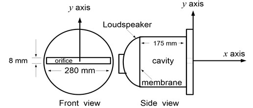
Fig. 1 presents that experimental model based on an isolated two-dimensional synthetic jet actuator (SJA), which includes a rectangular orifice, a cavity and an excitation mechanism. The dimensions of the SJA orifice are 280 mm (length) by 8 mm (width), the depth inside cavity in this actuator is 175 mm. A high-power loudspeaker was seamlessly bound to the surface outside the cavity without any leakage in order to provide an effective excitation mechanism. With the exception of the excitation mechanism, the structure of the actuator is made of almost entirely of acrylic. In the experiments, the SJA was driven using a sine wave of 160 Hz (resonance frequency of the cavity) under an excitation voltage of 15 V from a standard electrical signal generator and amplifier, respectively. The streamwise direction at the center the exit of the slot was established as the axis. Similarly, the transverse direction at the exit center of the slot perpendicular to the axis was set as the axis, as shown in Fig. 1. Instantaneous variations in the streamwise and transverse velocities of synthetic jets outside the cavity were measured using a cross hot-wire probe in conjunction with an HW-110 anemometric system. The sampling rate was set at 1000 Hz and the number of samples was set to 1000 points. An analog-to-digital (AD) converter was for acquiring the analog voltage to digital codes from sensors. Under the same operating conditions, few differences were observed in any of the data sets obtained from the measurement sensors. Most of the errors in data were from the instruments, which included an AD converter, hotwire anemometric system, and signal generator. These fluctuations in signals were sufficiently small to be neglected. Statistical methods were applied to the measured data. After taking into account the 95-percent confidence interval of the maximum velocity, error in the maximum velocity was within ±0.2 m/s.
Fig. 1Isolated two-dimensional synthetic jet actuator
3. Results and discussion
Synthetic jets are generally formed through the oscillation of a membrane associated with an excitation mechanism. When the membrane moves forward the orifice, air within the cavity is ejected followed by the appearance of vortex pair at the edge of the orifice. When the membrane moves away from the orifice under its own self-induced velocity, the vortex pair continues moving downstream from the exit under excitation of diaphragm resonance; i.e., it is not influenced by air pulled into the cavity. However, when the membrane moves forward the orifice, the synthetic jet appears around the orifice and cannot move very far from the exit of the orifice. The membrane moves away from the orifice, then the vortex pair is pulled into the cavity under excitation of cavity resonance. Hsiao et al. [19] found that synthetic jets excited by diaphragm resonance as well as cavity resonance can be employed in flow control; the former is used for flow control at long distance, such as flow mixing, free shear shedding, improving aerodynamic performance etc., the latter is suitable at short distance, such as boundary-layer control, heat transfer, improving aerodynamic performance etc. However, the resulting flow behavior has yet to be fully elucidated. The objective of the present paper is to investigate the flow behavior of a synthetic jet under excitation resulting from cavity resonance.
3.1. Flow behavior of synthetic jet in transverse direction
Using flow control of the synthetic jet actuator needs to understand its parameters. For an isolated two-dimensional SJA, whose characteristic in motionless flow major depend on three kinds of parameters [21, 22]: (1) the actuator geometric parameters, including the exit width , exit depth , cavity width and cavity depth ; (2) the implementing parameters, including the membrane oscillation (or piston amplitude) and excitation frequency ; (3) the working fluid parameters, including the fluid density and kinematic viscosity . These parameters of governing equation for behavior of a synthetic jet can be expressed as follows:
where is a time-averaged ejected velocity. According to the Buckingham theory, then , and are selected as repeatable fundamental dimensions. Moreover, the six dimensionless parameters can be formed in the following equation:
Above six independent parameters via the Buckingham π theory can be obtained as and . These parameters of - are fixed values with respect to design of a synthetic jet. Both and belong to operating parameters of a synthetic jet actuator. The quantity is a dimensionless parameter of the Reynolds number. Additionally, the quantity can be expressed as dimensionless stroke length. Besides, Eq. (3) is still simplified as Eq. (4):
The stroke length indicates the synthetic jet travel distance from exit orifice while the fluid is ejected out the cavity. , where is the entire period of the oscillating membrane and is the synthetic jet average orifice velocity, defined as in the Eq. (5):
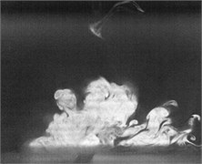
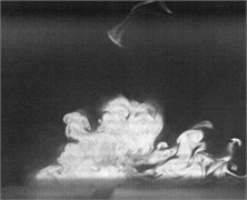
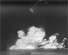
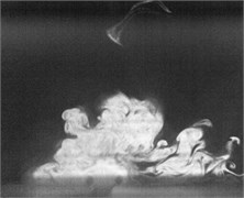
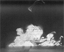
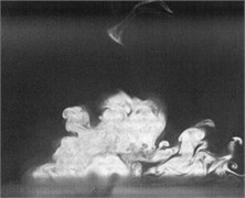
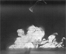
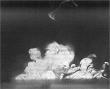
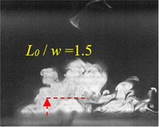
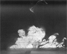
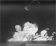
Fig. 2Flow visualization for formation of a synthetic jet using excitation of cavity resonance with 15 V sine wave (Total ejected period plus sucked period T= 0.00625 second)
a)0
b) 0.1
c)0.2
d)0.3
e)0.4
f)0.5
g)0.6
h)0.7
i)0.8
j)0.9
k)1
Flow visualization for formation of the synthetic jet at the cavity resonance has been obtained that its dimensionless stroke length is less than that of the resonance of diaphragm and the response of its exit velocity at the SJA orifice is strong better than other excitation frequencies except the resonance of diaphragm.
For the resonance frequency in cavity, it takes place at 160 Hz, the flow characteristic of external SJA needs to discuss further in this investigation. The characteristics of resonance with the SJA cavity has been done in some literatures [16-18, 21-29], but these results at excitation of cavity resonance aren’t still described clear about the external flow characteristics of the SJA.
In order to obtain flow visualization outside the cavity at excitation of cavity resonance, using a high-speed camera of MotionPro X4 is to capture images with sampling rate setting at 2000 pictures per second. The oscillating cycle of membrane for the excitation mechanism in the periodic time is 0.00625 second. These images in shown Fig. 2 reveal formation of the synthetic jet at cavity resonance with 15 V sine wave from flow visualization. While the flow ejected out the cavity, the dimensionless stroke length at cavity resonance is calculated as 1.5. Evidently, the flow stops traveling along downstream of center from exit orifice during the flow sucked into the cavity. In contrast, the flow begins to travel into the cavity. To this point, it makes a difference between the resonance of diaphragm and the cavity resonance. From the results in Fig. 2, it needs to obtain also flow field outside the synthetic jet actuator with the hot-wire measurements.
In Fig. 3, the synthetic jet is excited with a sine wave of 160 Hz at 15 V, wherein the mean velocities () of synthetic jets were measured along different transverses perpendicular to the exit slot are measured. Here refers to the 8 mm width of the exit slot.
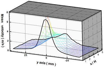
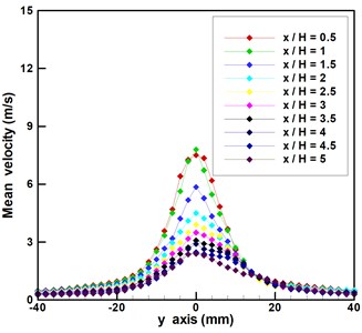
Fig. 3(a) shows the three-dimensional relation among the average velocity, transverse distance (-axis) and downstream distance () for the description of the behaviors of synthetic jets. It appears that the optimal mean velocity of the synthetic jet occurs at 0. In other words, the velocity at the center of the orifice exit is the highest than any of transverses. To gain a more comprehensive understanding of vortex formation, we compared the transverse mean velocities of the synthetic jet from –40 mm to 40 mm (–5 5). From the results in Fig. 3(b), it is clear that the mean velocity of (in the range of -0.5 to 0.5), whereas the mean velocities of ranges (in the range of 0.5 to 1) are all beyond 6 m/s. Beyond this point, the transverse mean velocities continue decreasing as the synthetic jet moves away from the orifice. The results in Fig. 3(b) indicate that the mean velocities reached approximately 1 m/s in every transverse from –20 mm to 20 mm when the synthetic jet moves downstream as far as 5. According to the above description, plane regions of 0 5 and –2.52.5 could be used for flow control.
Fig. 3a) Three-dimensional relationships among mean velocity, y-axis, and x/H; b) mean velocity versus y-axis of a synthetic jet
a)
b)
3.2. Flow behavior of synthetic jet in downstream direction
In the following, our work focuses on the relationship between the streamwise mean velocities and traveling distance for several transverses at 0, 0.5, 1, 1.5, 2, 2.5 and 3, as shown in Fig. 4. For the transverse 0, the downstream mean velocity reached 8 m/s at the exit of the orifice ( 0) and then decreased suddenly to 7.16 m/s at 4 mm (or 0.5). One explanation would be that the flow was ejected from the orifice by the oscillation of the membrane before a vortex was produced.
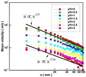
The mean velocity begins increasing after the flow passes this point ( 0.5), which is an indication that the pair of vortices have developed. When the flow passes 1, its mean velocity reaches another peak (i.e., the mean center velocity reaches 7.5 m/s), whereupon it drops rapidly until the flow is pulled into the cavity and disappears in the air. This result can also be explained as follows. When the pair of vortices become sufficiently large, the velocity begins decreasing. It is interesting to note that the mean velocity is inversely proportional to the distance from the orifice exit except at 0 and 0.5 in the case of 0. The same trend in Fig. 4 means that the mean velocities are also inversely proportional to distance from the orifice exit in the case of transverses of 0.5, 1, 1.5, 2, 2.5, and 3. Fig. 5 presents the results obtained by taking the logarithm of the data in Fig. 4. The slopes obtained by curve fitting fall between –7/10 and –3/5 for the synthetic jet under excitation of cavity resonance using a sine wave 160 Hz at 15 V.
Fig. 4Mean velocity versus downstream distance from synthetic jet
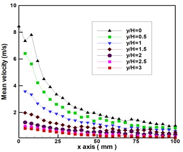
Fig. 5Logarithm of mean velocity and downstream distance from synthetic jet
3.3. Characteristic frequencies of flow field
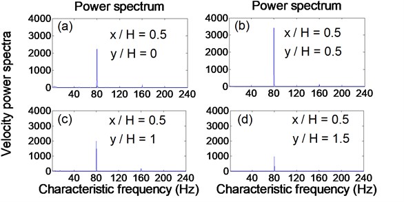
This section concentrates on the study of characteristic frequency from near to far field associated with a synthetic jet under excitation from cavity resonance. The original data of velocity at the center of the orifice exit (0 and 0) were obtained by fast Fourier transform, as shown in Fig. 6. The excitation frequency is 160 Hz; however, there are two characteristic frequencies at 80 Hz and 160 Hz in the flow field. When the synthetic jets locate at different transverses ( 0.5, 1, 1.5 and 2) for the same downstream location ( 0.5), the variation of characteristic frequencies can be observed in Fig. 7.
Initially, data in the exit center of the orifice ( 0 and 0) was obtained using cross hot-wire measurement, which manifest as frequencies at 80 Hz and 160 Hz. The generation of the characteristic frequency at 80 Hz can be attributed to the collision of the upper and lower vortices of the synthetic jet. The other characteristic frequency at 160 Hz is an excitation frequency. It should be noted that the density of the power spectrum at the characteristic frequency at 160 Hz is higher than at other frequencies.
The cross hot-wire probe was moved to 0.5 for four different transverses, as shown in Fig. 7. The sequence of development of the vortex in the synthetic jet can be clearly observed in Figs. 7(a) to 7(d). When the vortex began forming at 0.5 and 0 at the downstream center of the orifice exit, only one a characteristic frequency was observed at 80 Hz, at which point the other characteristic frequency at 160 Hz disappeared, as shown in Fig. 7(a). As the vortex of the synthetic jet gradually enlarged, the hot-wire probe was moved to another location at 0.5 and 0.5. At this point, the characteristic frequency at 80 Hz suddenly increased, as shown in Fig. 7(b), whereupon the velocity power spectra of this characteristic frequency decreased gradually with an increase of , as shown in Figs. 7(c) and 7(d). The hot-wire probe continued to move downstream until 8, at which point only the characteristic frequency at 80 Hz remained within the flow field, and it gradually dissipated into the flow field.
Fig. 6Relationship between velocity power spectra and characteristic frequency at center of orifice exit (x/H= 0 and y/H= 0)
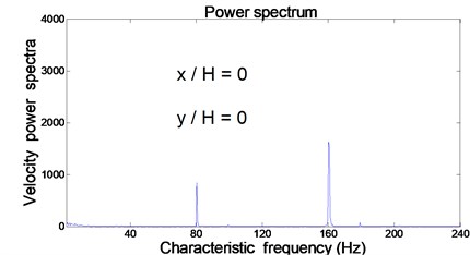
Fig. 7Relationship between velocity power spectra and characteristic frequency at different downstream locations from a synthetic jet
4. Conclusions
The paper uses the hot-wire measurement to examine the flow behavior produced by the excitation of an isolated two-dimensional synthetic jet actuator via cavity resonance. Our experiment results demonstrate that the vortex pairs in synthetic jets cannot travel very far from the exit of the orifice. This is contrary to the findings in previous studies, in which such vortex pairs were reported as continuing downstream due to excitation under normal conditions. Other findings in this study appear to contradict the results from previous studies. For example, the planar regions at 05 and –2.52.5, which represent a relatively small field near the exit of the orifice, can be considered an effective flow control in this study. Numerous researchers have shown that synthetic jets can be used for flow control; however, many of these works have encountered difficulties in separating resonance frequencies related to the diaphragm from those related to the cavity. In this study, we have largely overcome this problem; however, the flow characteristics of synthetic jets excited by cavity resonance remain too short to provide a sufficient degree of control over flow. Further analysis of the relationship between mean velocities () and downstream distance () for the synthetic jet in different transverses, must be performed by taking the logarithm of both parameter, and using the curve fitting method, to obtain a linear relationship. The resulting slop values are between –7/10 and –3/5. Finally, the original time-domain data was converted into a power spectrum using fast Fourier transform in order to further elucidate the flow characteristics of synthetic jets, our results identified that the characteristic frequencies at 80 Hz and 160 Hz measured at the center of the orifice exit. The frequency at 80 Hz can be attributed to a collision between the upper and lower vortices of the synthetic jet. The latter frequency at 160 Hz can be attributed to the excitation frequency of the signal source. Finally, we used hot-wire measurement to investigate the mechanism underlying the formation of vortices in synthetic jets in order to elucidate the overall flow characteristics. Our results from the hot-wire measurement demonstrate that the excitation frequency at 160 Hz disappears downstream; however, the characteristic frequency at 80 Hz lasts until 8. These experimental results make a valuable contribution to the further development of flow control in the future.
References
-
Robson N. Turbulator diameter and drag on a sphere. ISB Journal of Physics, 2009, p. 1-4.
-
Lin J. C. Review of research on low-profile vortex generators to control boundary-layer separation. Progress in Aerospace Science, Vol. 38, 2002, p. 389-420.
-
Smith B. L., Glezer A. The formation and evolution of synthetic jets. Physics of Fluids, Vol. 10, 1998, p. 2281-2297.
-
Chen Y., Liang S., Aung K., Glezer A., Jagoda J. Enhanced mixing in a simulated combustor using synthetic jet actuators. AAIA Paper No. 99-0449, 1999.
-
Ingard U., Labate S. Acoustical circulation effects and the nonlinear impedance of orifices. Journal of the America, Vol. 22, 1950, p. 211-218.
-
Hsiao F. B., Liu C. F., Shyu J. Y. Control of wall-separated flow by internal acoustic excitation. AIAA Journal, Vol. 28, Issue 8, 1990, p. 1440-1446.
-
Mallinson S. G., Reizes J. A., Hong G. An Experimental and numerical study of synthetic jet flow. Aeronautical Journal, Vol. 105, 2001, p. 41-49.
-
Mallinson S. G., Reizes J. A., Hong G., Westbury P. S. Analysis of hot-wire anemometry data obtained in synthetic jet flow. Experimental Thermal and Fluid Science, Vol. 28, 2004, p. 265-272.
-
Mahalingam R., Glezer A. Design and thermal characteristics of a synthetic jet ejector heat sink. ASME Journal of Electron, Packaging, Vol. 127, Issue 2, 2005, p. 172-177.
-
Pavlova A., Amitay M. Electronic cooling using synthetic jet impingement. ASME Journal of Heat Transfer, Vol. 128, Issue 9, 2006, p. 897-907.
-
Davis S., Glezer A. Mixing control of fuel jets using synthetic jet technology. AIAA Paper No. 99 0447, 1999.
-
Amitay M., Smith B., Glezer A. Aerodynamic flow control using synthetic jet technology. 36th Aerospace Sciences Meeting and Exhibit, 1998.
-
Seifert A., Eliahu S., Greenblatt D., Wygnanski I. Use of piezoelectric actuators for airfoil separation control. AIAA Journal, Vol. 36, Issue 8, 1998, p. 1535-1537.
-
Rathnasingham R., Breuer K. Active control of turbulent boundary layers. Journal of Fluid Mechanics, Vol. 495, 2003, p. 209-233.
-
Lin C. Y., Hsiao F. B. Experimental study of flow separation over NACA 633018 wing with synthetic jet control at Reynolds numbers. Journal of Mechanics, Vol. 29, Issue 1, 2013, p. 45-52.
-
Lee C., Hong G., Ha Q. P., Mallinson S. G. A piezoelectrically actuated micro synthetic jet for active flow control. Sensors and Actuators A, Vol. 108, 2003, p. 168-174.
-
Krishnan G., Mohseni K. An experimental and analytical investigation of rectangular synthetic jets. Journal of Fluids Engineering, Vol. 131, 2009, p. 121101.
-
Chaudhari M., Verma G., Puranik B. Frequency response of a synthetic jet cavity. Experimental Thermal and Fluid Science, Vol. 33, 2009, p. 439-448.
-
Lin C. Y., Bai C. J., Hsiao F. B. An Investigation on fundamental characteristics of synthetic jet actuator under excitation condition at resonances. Procedia Engineering, Vol. 79, 2014, p. 35-44.
-
Pierce A. D. Acoustics. 1st Edition, McGraw-Hill, New York, 1981, p. 330-333.
-
Zhong S., Jabbal M., Tang H., Garcillan L., Guo F. S., Wood N., Warsop C. Toward the design of synthetic jet actuators for full scale flight conditions. Part 1: The fluid mechanics of synthetic jet actuators. Flow, Turbulence and Combustion, Vol. 78, 2007, p. 283-307.
-
Wang J., Shan R., Zhang C., Feng L. Experimental investigation of a novel two-dimensional synthetic jet. European Journal of Mechanics B/Fluids, Vol. 29, 2010, p. 342-350.
-
Feero M. A., Lavoie P., Sullivan P. E. Influence of cavity shape on synthetic jet performance. Sensors and Actuators A, Vol. 223, 2015, p. 1-10.
-
Chanaud R. C. Effects of geometry on the resonance frequency of Helmholtz resonators. Journal of Sound and Vibration, Vol. 178, 1994, p. 337-348.
-
Shi X., Mak C. M. Helmholtz resonator with a spiral neck. Applied Acoustics, Vol. 99, 2015, p. 68-71.
-
Saadat Y., Fernandez N., Samimi A., Alam M. R., Shakeri M., Ghorbani R. Investigating of Helmholtz wave energy converter. Renewable Energy, Vol. 87, 2016, p. 67-76.
-
Chanaud R. C. Effects of geometry on the resonance frequency of Helmholtz resonators. Part 2. Journal of Sound and Vibration, Vol. 204, Issue 5, 1997, p. 829-834.
-
Meissner M. Excitation of Helmholtz resonator by grazing air flow. Journal of Sound and Vibration, Vol. 256, Issue 2, 2002, p. 382-388.
-
Nair S. U., Shete C. D., Subramoniam A., Handoo K. L., Padmanabhan C. Experimental and computational investigation of coupled resonator-cavity systems. Applied Acoustics, Vol. 71, 2010, p. 61-67.
About this article
The work was supported by the Ministry of Science and Technology of Taiwan under grant MOST 103-2218-E-344-001. Additionally, one of authors would like to thank Professor Fei-Bin Hsiao for his academic guidance.
