Abstract
Inerter is a recent advancement in vehicle suspension that have been shown to be capable of improving vehicle ride comfort, however its ride improvement is less encouraging in the parallel layout. This study investigated the possibility of further ride improvement brought by vehicle suspensions with a switchable parallel inerter instead. In this theoretical study, the inerter was assumed to be on-off switchable based on semi-active force cancellation strategy. A two-degree-of-freedom quarter vehicle model was used to evaluate several cases of suspension system, which included ordinary passive suspension as reference, a system with switchable inerter and a system with both switchable damper and inerter. The model was solved mathematically with random road profile and step profile as ground excitations. Results showed that the use of switchable inerter in parallel to spring and damper in the different test cases was capable of reducing vertical sprung mass acceleration by a healthy 12 %, which is far superior to a mere 2 % achieved by a passive parallel inerter, as well as comparable to that achieved by a switchable damper. When both sprung mass acceleration and dynamic tire load were considered, comparison made on the Pareto fronts indicated that the switchable capability of an inerter managed to further improve the Pareto optimal sets over those obtained for cases with passive inerter.
1. Introduction
A vehicle suspension is a system of spring and damper in a vehicle that serves multiple purposes. Its primary function is to isolate the chassis from vibrations due to roughness of the road. This vibration isolation capability is better known as ride comfort in the context of suspension performance. Additionally, it also ensures tire-road contact with minimal load variations for good road holding ability and, indirectly, good handling of vehicle [1]. Ride and road holding ability are, therefore, two important performance criteria when designing vehicle suspensions.
The quest for continuous improvement in suspension performance has resulted in various advancements in vehicle suspension, a recent one being the introduction of a new element which is the inerter. According to definition [2], an inerter is a two-terminal suspension element with the property that the equal and opposite forces at the two terminals is proportional to the relative acceleration between them, as stated in Eq. (1):
in which and are the accelerations of terminals 1 and 2 respectively, is the defined equal and opposite force, while is a proportionality constant which is known as the inertance [2] and has the unit of kilogram. Inerter is an effectively two-terminal mass in suspension systems [3].
Previous researches have shown that the passive inerter is effective as a method of isolating vibrations from the ground in several suspension applications. Some notable applications include (i) in building suspensions [4] where the benefit is reminiscent of that brought by a tuned mass damper, (ii) in train suspensions [5, 6], and (iii) in passive vehicle suspensions [3, 7, 8]. In the case of passive vehicle suspensions, improvements to both performance measures of ride and road holding ability have been demonstrated with optimum suspension parameters. However, although the ride benefit of vehicle suspensions with passive inerter has been proven possible, it is not entirely promising. For instance, while the study by Smith and Wang [7] has shown solid improvement in ride using the parallel inerter suspension layout at high suspension stiffness, the same brought by a parallel inerter is less encouraging at low suspension stiffness which is usually associated with passenger vehicles. To add to this, the study by Soong et al. [8] showed that the ride improvement of a passive parallel inerter remained the same when paired with either passive or semi-active suspensions. Nonetheless, such studies [8, 9] also demonstrated that it is at least possible to implement both concepts of inerter and semi-active suspension together. Considering that both are capable of giving vehicle ride benefit, apart from pairing a passive inerter to a semi-active suspension, a more interesting implementation is to adopt semi-active control strategy on an inerter to allow the inerter force to be controlled, giving rise to a variable or switchable inerter which is a logical step up from a passive inerter.
This is a study about the implementation of such a switchable inerter in vehicle suspensions, in which the inerter was assumed to be on-off switchable based on semi-active force cancellation strategy. In the study, the potential ride improvement brought by a passenger vehicle suspension with this switchable parallel inerter over the ordinary passive suspension was investigated. Through the analysis as presented in subsequent sections, it was found that the switchable inerter was superior to the passive inerter as it further enhanced the ride performance benefit demonstrated by passive inerter in the earlier studies.
2. Mathematical modeling and simulation
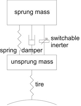
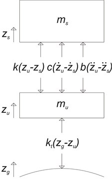
The analysis of on-off switchable inerter for various cases was carried out mathematically using a quarter vehicle model (QVM). Consistent to some past studies [3, 8], the simple parallel layout was considered in this study, in which the spring, damper and the on-off switchable inerter acted in parallel to one another between the sprung and unsprung masses of a QVM. Fig. 1(a) shows the QVM with simple parallel inerter layout, while the two equations of motion, Eq. (2) and Eq. (3) can be formulated from the corresponding free-body diagram as in Fig. 1(b).
Fig. 1a) The schematic diagram and b) the free-body diagram of a QVM with parallel inerter
a)
b)
in which and are the sprung and unsprung mass displacements, and are the corresponding velocities, and are the corresponding accelerations, and are the sprung and unsprung mass values, is the ground displacement, is the tire stiffness, , and refer to the spring stiffness, damping coefficient and inertance of the suspension respectively. It can be noted that the inerter, like other suspension elements such as spring and damper, was modeled as a massless force element according to its ideal definition without considering the non-linearities of the physical device. Similarly, the tire was represented as linear spring force with constant tire stiffness. In this study, the QVM was solved numerically in Simulink® to obtain sprung and unsprung mass responses.
2.1. Force cancellation strategy
The core idea of this study centers on adopting a semi-active suspension control strategy usually applicable to switchable damper, and implementing it on the inerter instead. In this study, the force cancellation strategy, also known as the force balance logic, was adopted. This is a control strategy that is used in semi-active and active vehicle suspensions to achieve better ride comfort in comparison to conventional passive suspensions. The basic idea of this strategy, when applied to switchable damper, is to balance the spring force by means of the damper force as long as they act in opposite directions, and to set damper force either to zero or more realistically to a minimum value when the forces have the same direction [10]. For example, for a two-state switchable damper, the switching algorithm can be represented as Eq. (4):
in which and are the minimum and maximum damping coefficients.
The implementation of an on-off switchable inerter in this study involves similar control strategy. In this case, however, the inerter force (or both inerter and damper forces in some tests) is used to oppose the spring force. While Eq. (4) is applicable to switchable damper, the switching algorithm for inerter is slightly modified:
in which is the on-state inertance and is the off-state inertance which is set to be zero in this study.
In general, the implementation of this discrete switching algorithm requires varying the inertance of a switchable or variable inerter device. At this point it is worth noting that this study is of theoretical nature, the intention of which is to understand the performance potential of having switchable inertance, , in the system of vehicle suspension. However, it should also be noted that the actual realization of such variable-inertia device has been shown possible in recent studies. For instance, Li and Liang [11] have demonstrated the realization of a variable hydraulic-based two-terminal inerter device for which the equivalent inertial mass was adjustable using an electro-hydraulic proportional valve.
Although this study is only of performance assessment, a possible actual realization of the on-off switchable inerter, going along the direction of hydraulic inerter introduced in several past studies [11, 12], is still proposed schematically here, as in Fig. 2.
The working principle of a hydraulic inerter can be found in the related past study [12]. To summarize, basically the working of this type of inerter comes from the inertia of a flywheel, which is rotated by the hydraulic motor due to the flow of hydraulic medium from one cylinder chamber to the other, when there is a pressure difference between the chambers generated by an application of force at the two device terminals. In a hydraulic inerter, the hydraulic flow provides the linear-to-rotational motion conversion, similar to other conversion methods such as the rack-and-pinion [13] and ball-screw [14] mechanisms.
Fig. 2The schematic diagram of a possible realization of switchable inerter
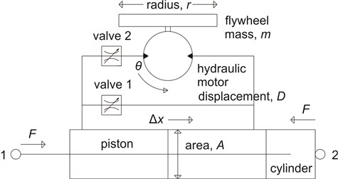
Considering ideal conditions, the linear flow rate at the cylinder and the rotational flow rate at the hydraulic motor are equal; similarly, the input power due to linear movement of the piston and the output power of the rotating mechanism are equal. These give Eq. (6) and Eq. (7) respectively:
in which represents the relative movement between the two terminals, represents the rotational movement, is the cross-sectional area of the piston, is the displacement of the hydraulic motor in m3rad-1, is the force at the terminals and is the torque at the flywheel. Combining Eq. (6) and Eq. (7), considering where is the flywheel’s moment of inertia, the characteristic equation of an inerter, Eq. (8), is obtained:
By comparing Eq. (8) with the definition of inerter (Eq. (1)), considering the usual adoption of cylindrical flywheel with , the effective inertance, , which is the center of attention in this study, is related to the design parameters as in Eq. (9), in which the parameters are as already defined:
Assuming this hydraulic realization of inerter, the semi-active force cancellation strategy’s switching algorithm can be executed through flow control using variable valves. This is actually similar to the methods used in relevant studies [11, 15]. For the application of on-off switchable inerter in this study, the on state will be achieved when valve 1 is closed and valve 2 is open based on voltage control (Fig. 2). Under this situation, the on-state inertance is basically dictated by Eq. (9). Conversely, the off state will be achieved when the opposite is true. Considering insignificant inertia due to the mass of hydraulic medium, the off-state inertance is basically negligible. The description here shows that the idea of having a switchable inerter to be used in vehicle suspensions is practically achievable. In fact, a recent study [15] has demonstrated, with similar valve control, the switching of a vehicle suspension between the (hydraulic) inerter-spring-damper mode and the hydraulically interconnected suspension (without inerter) mode.
Finally, it is worth to note that the force cancellation strategy was chosen to be implemented on the switchable inerter because of the complementary nature of the inerter element to the spring element in suspension systems. In a previous study on the effectiveness of a parallel inerter in vibration isolation, Soong et al. [8] have pointed out the anti-phase property between an inerter and a spring in the parallel layout, where the inerter force and the spring force of a vehicle suspension due to ground disturbance were opposing each other. The choice of adopting force cancellation strategy, as in Eq. (5), is simply in line with the parallel inerter’s inherent ability of opposing and canceling the spring force.
2.2. Test cases and setup of analysis
Simulations were carried out to determine the response of sprung and unsprung masses for several cases of suspension system which included an ordinary passive suspension, suspensions with passive inerter, and suspensions employing switchable inerter. To clarify, the spring-damper-inerter combinations are summarized in Table 1.
Table 1Combinations of suspension forces in the tests
Suspension case | Spring force | Damper force | Inerter force |
1 | Passive | Passive | – |
2 | Passive | Passive | Passive |
3 | Passive | Switchable | Passive |
4 | Passive | Passive | Switchable |
5 | Passive | Switchable | Switchable |
As described in Table 1, five cases were considered in the study; cases 1, 2 and 3 were treated as reference cases for comparison with the test cases employing switchable inerter, namely cases 4 and 5. For cases 3, 4 and 5 which involved switchable damper and inerter forces, the forces were determined based on the force cancellation strategy with switching algorithms as outlined in Eq. (4) and Eq. (5) respectively.
Since this study focuses on vehicle ride analysis, it is logical to choose parameter values of vehicle for which ride comfort is of primary concern. Hence, the values used throughout the study belong to those of a passenger vehicle [16]: 317.5 kg, 45.4 kg, 22000 Nm-1, 1500 Nsm-1, 192000 Nm-1. To ensure consistency in the results, for all cases involving switchable damper, the maximum damping coefficient was set to be 1500 Nsm-1, which is identical to the passive damping coefficient of the reference case. The minimum damping coefficient was set to be approximately half of the passive damping coefficient value, hence the value of 900 Nsm-1, which is the same as that used in a similar study [17] involving switchable damper. On the other hand, the determination of passive and on-state inertance values took a different approach. While the off-state inertance was meant to be zero as there should be no inerter force acting on the system whenever it was switched off, the passive inertances in cases 2 and 3, and the on-state inertances in cases 4 and 5 were determined by iteratively enumerating each system with inertance values ranging from 0 to 320 kg. The selection of this range is similar to another study [3] which considered a range from zero to one for the ratio between inertance and sprung mass during analysis. For this part of analysis, a simple exploration on design space is sufficient, since the system which involves only two degrees of freedom (DOF) and single design variable can be solved quickly. For evaluation based on single objective of ride only, in each case the inertance that gave minimum root-mean-squared (RMS) sprung mass acceleration was chosen as optimum passive or on-state inertance, and the response due to optimum inertance was analyzed. For evaluation considering multiple objectives (ride and road holding ability), responses due to all inertances within the range were simulated, and the non-dominated Pareto solutions were determined to assess the relationship between RMS sprung mass acceleration and RMS dynamic tire load. In addition, Pareto solutions considering both damping coefficient and inertance as design variables were also determined through optimization for a more comprehensive analysis.
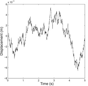
Referring to Fig. 1, the input to a QVM is the tire force which is generated due to ground excitation in the form of vertical road displacements. In the study, random road profile was primarily used in simulations to emulate ground excitation experienced due to normal driving conditions. A single track is generated by adding together a discrete number of sine waves; the amplitude is derived from spectral density data, while the phase angles are determined through a random number generator [16]. This, together with the road roughness coefficient from ISO 8608:1995 [18], was used in the study to create an ISO 8608:1995 class A random road profile (smooth road classification), which is shown in Fig. 3(a).
In addition, for single-objective evaluation, after the optimum inertances were determined, for each case the QVM with optimum inertance was solved again using step profile instead of random road profile to obtain the corresponding step response. Step profile is an emulation of a vehicle striking a curb, which can occur occasionally during driving. Moreover, step profile is commonly used as input to control system to evaluate the transient response of the system. Fig. 3(b) shows the step input used in the study, which has a height of 0.1 m.
Fig. 3Representation of a) class A random road profile and b) step profile with step time shifted from 0 to 1 s for clarity
a)
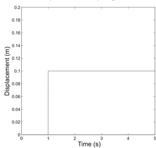
b)
3. Simulation results and discussion
The five cases of suspension system were tested using the two-DOF QVM to analyze the sprung and unsprung mass responses due to ground excitations such as the random road input and the step input. For each case, the random road profile was used to obtain common suspension performance parameters such as the RMS sprung mass acceleration, RMS dynamic tire load and RMS suspension deflection. This was followed by step input to study transient system behavior characterized by the rise time, peak time, the corresponding percent overshoot and the settling time. The optimum inertances were used in obtaining the results, which are summarized in Table 2.
3.1. Evaluation based on single objective
3.1.1. Random road response
By varying inertance across the range, it was found that optimum inertance existed for each case of suspension system which gave lowest RMS sprung mass acceleration. Note that case 1 did not require determination of optimum inertance as the suspension system was made up of only spring and damper. Also, whenever switchable inerter was involved, the off-state inertance was set to be zero; hence, only the optimum on-state inertance was determined.
When tested with random road input, the results showed that the RMS sprung mass acceleration of all cases with inerter were reduced and there were increases in RMS dynamic tire load. A reduction in RMS sprung mass acceleration implies ride improvement, as lower acceleration or lower resultant force is experienced by the passengers in the vehicle body. On the other hand, an increase in RMS dynamic tire load is generally undesirable as this means greater tire normal load variation which results in less road holding ability.
Table 2Summary of results due to random road input and the corresponding transient responses due to step input
Parameter | Case 1 | Case 2 | Case 3 | Case 4 | Case 5 |
Random road response | |||||
Optimum inertance (kg) | – | 6 | 5 | 14 | 8 |
RMS sprung mass acceleration (ms-2) | 0.1719 | 0.1682 | 0.1470 | 0.1600 | 0.1429 |
RMS dynamic tire load (N) | 101.569 | 107.242 | 114.220 | 110.539 | 115.897 |
RMS suspension deflection (×10-3 m) | 1.248 | 1.246 | 1.291 | 1.158 | 1.232 |
Transient response | |||||
Rise time (s) | 0.1181 | 0.1211 | 0.1560 | 0.1642 | 0.2002 |
Peak time (s) | 0.3418 | 0.3448 | 0.3990 | 0.4003 | 0.4533 |
Percent overshoot (%) | 53.7161 | 52.9458 | 46.3617 | 36.2294 | 37.1956 |
Settling time (s) | 2.0307 | 2.0469 | 2.1975 | 1.7715 | 2.2251 |
RMS sprung mass acceleration (ms-2) | 2.0046 | 1.9633 | 1.6748 | 1.7616 | 1.5541 |
RMS dynamic tire load (N) | 1164.2 | 1226.4 | 1316.0 | 1244.5 | 1327.2 |
RMS suspension deflection (m) | 0.0156 | 0.0156 | 0.0165 | 0.0149 | 0.0168 |
Referring to Table 2, treating case 1 as reference, it can be seen that the case with passive inerter (case 2) brought only slight decrease in RMS sprung mass acceleration, cases with either switchable damper or inerter (cases 3 and 4) gave noticeably greater reduction in the parameter, while cases with both switchable damper and inerter (case 5) resulted in the most reduction.
Results from Table 2 shows that for the parallel inerter force to work and result in an improvement in ride, the suitable inertances occurred at a low value range for the passenger vehicle parameters used in this study. The optimum inertances for suspension cases involving passive inerter were lower than the optimum on-state inertances for cases involving switchable inerter. The low inertance range generally showed agreement to earlier research [7] which noted that the parallel layout requires lower value of inertance than other layouts such as the serial layout when it is optimized for ride quality. Since the optimum inertances occurred at low values for all cases involving inerter (cases 2 to 5), it is worth analyzing the degree of variation in RMS sprung mass acceleration for each of the mentioned cases when the inertance is varied from zero to the optimum value. This is to determine whether or not the switchable inerter implementation is a worthwhile replacement to the passive inerter implementation, since the former has to show greater rate of performance parameter improvement than the latter to be considered as superior. The analysis is shown in Table 3. Judging from the percentage difference and the average rate of change of performance parameter (RMS sprung mass acceleration), it can be observed that the improvement in ride performance for cases with switchable inerter was more sensitive to the variation of inertance than that for cases with passive inerter. Specifically, cases 4 and 5 showed greater degree of improvement in RMS sprung mass acceleration per inertance than cases 2 and 3 respectively.
Table 3Variations of RMS sprung mass acceleration from zero to optimum inertance
Parameter | Case 2 | Case 3 | Case 4 | Case 5 |
RMS sprung mass acceleration at zero inertance (ms-2) | 0.1719 | 0.1507 | 0.1719 | 0.1507 |
RMS sprung mass acceleration at optimum inertance (ms-2) | 0.1682 | 0.1470 | 0.1600 | 0.1429 |
Percent difference (%) | –2.1397 | –2.4595 | –6.8899 | –5.1811 |
Average rate of change of RMS sprung mass acceleration (×10-3 ms-2kg-1) | –0.613 | –0.741 | –0.846 | –0.976 |
An interesting observation can be made from the RMS suspension deflection, which represents the rattle space requirement of a suspension and should ideally be minimized. From the results, cases 1 and 2 had almost identical RMS suspension deflection values. This is consistent to the past study [3] which mentioned that paralleling a passive two-terminal flywheel cannot improve the deflection performance of the suspension. Meanwhile, for cases involving force cancellation strategy (cases 3 and 5), the RMS suspension deflections were greater than the passive suspension cases. This indirectly leads to an inference of worsen performance for load disturbances, since greater RMS suspension deflection reflects a more softly sprung suspension which is known to deteriorate the performance in situations involving load transfer. Case 4, however, is an interesting exception as it had lower RMS suspension deflection than even reference case 1. While other suspension cases with force cancellation strategy attempted to minimize the resultant force acting between sprung and unsprung masses, the cancellation of spring force due to switchable inerter in case 4 left behind damper force that acted between the masses, causing the oscillations of the masses to be controlled. Because suspension deflection is a measure of relative motion between sprung and unsprung masses, its RMS value was lowered.
3.1.2. Transient response
Meanwhile, when simulated using step input, results in terms of the RMS parameters were consistent to those due to random road input. This shows that the use of passive and switchable inerter could be beneficial not just in normal driving situations but also in transient events which are occasionally encountered. The sprung mass acceleration and dynamic tire load in time domain are shown in Fig. 4(a) and Fig. 4(b) to aid comparison further.
Fig. 4(a) Sprung mass acceleration and (b) dynamic tire load for various cases due to 0.1 m step input
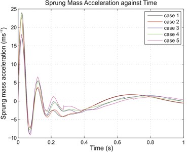
a)
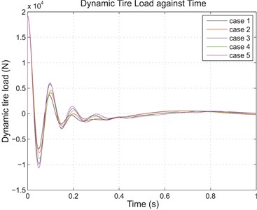
b)
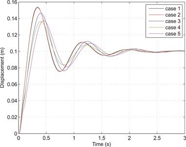
Apart from the RMS parameters, for simulations with step input, the sprung mass response was also analyzed to determine the transient characteristics of the systems. Generally, for a comfortable ride, longer rise time and peak time are desirable as these mean less impact is experienced by the passengers. Conversely, lower percent overshoot and shorter settling time are preferred as these indicate less oscillatory response, hence less bumpy ride. From Table 2, with ordinary passive suspension (case 1) as reference, the use of inerter, both passive and switchable, gave better effect to sprung mass response. From cases 2 to 5, the respective rise time and peak time were longer, and there was reduction in percent overshoot for each case when compared to reference case 1. These represented ride improvement. The only observed disadvantage of having inerter force came in the form of increased settling time, with case 4 again being the only exception. The transient sprung mass responses for various cases are shown collectively in Fig. 5, in which improvements in the transient characteristics like the overshoot and the settling are immediately observable, particularly for case 4 with switchable inerter but passive damper.
Fig. 5Transient responses of sprung mass due to 0.1 m step input
To sum up this part of analysis, several comparisons can be made between the test cases and the reference cases to evaluate the effectiveness of implementing the on-off switchable inerter based on force cancellation strategy. Firstly, by referring to the results of case 4 and reference case 1 (Table 2), there was an improvement in ride as the RMS sprung mass acceleration with random road input was decreased by 6.92 % (12.12 % for step input). Taking this as a suspension performance indicator, the percent improvement for step input was especially comparable to those attained by semi-active suspension systems employing only switchable damper. To further strengthen this point, an extra comparison was made between case 4 (the representative case of using switchable inerter) and an add-on case of having only switchable damper with the same control strategy, taking of course case 1 (representative case of having ordinary passive suspension) as the reference. This is shown in Table 4.
The comparability of a switchable inerter with a switchable damper can be seen from Table 4, in which the improvement in RMS sprung mass acceleration due to step input was 12.12 % as stated earlier, while the improvement brought by a switchable damper was 13.66 %. Both were very close.
Table 4Performance comparison between a switchable inerter and a switchable damper
Parameter | Case 1 | Case damper | Difference (%) | Case 4 | Difference (%) |
Random road response | |||||
Optimum inertance (kg) | – | – | 14 | ||
RMS sprung mass acceleration (ms-2) | 0.1719 | 0.1507 | –12.33 | 0.1600 | –6.92 |
RMS dynamic tire load (N) | 101.569 | 108.291 | 6.62 | 110.539 | 8.83 |
RMS suspension deflection (×10-3 m) | 1.248 | 1.296 | 3.85 | 1.158 | –7.21 |
Transient response | |||||
Rise time (s) | 0.1181 | 0.1521 | 28.79 | 0.1642 | 39.03 |
Peak time (s) | 0.3418 | 0.3959 | 15.83 | 0.4003 | 17.12 |
Percent overshoot (%) | 53.7161 | 47.6422 | –11.31 | 36.2294 | –32.55 |
Settling time (s) | 2.0307 | 2.1837 | 7.53 | 1.7715 | –12.76 |
RMS sprung mass acceleration (ms-2) | 2.0046 | 1.7308 | –13.66 | 1.7616 | –12.12 |
RMS dynamic tire load (N) | 1164.2 | 1253.5 | 7.67 | 1244.5 | 6.90 |
RMS suspension deflection (m) | 0.0156 | 0.0166 | 6.41 | 0.0149 | –4.49 |
While still being in the comparative evaluation of these two, it is probably worth to diverge a little to discuss some advantages of using a switchable inerter over a switchable damper. In terms of other performances (ride performance has been discussed), as highlighted by Table 4, a switchable inerter gave notably greater improvements in suspension deflection, as well as rise time, overshoot and settling of transient response, compared to those achieved by a switchable damper (which were already better than ordinary passive suspension). Discussing slightly further, in terms of physical structure, a switchable inerter does offer a possibility not found in a typical fluid-based switchable damper. Because inerter device is typically metallic-flywheel-based, it can be exploited as a conductor to incorporate electromagnetic damping easily, which in turn makes regenerative damping possible. In fact, a related study [19] has pointed out that a typical regenerative suspension device can be modeled as a parallel combination of inertance and dissipative (damping) components. On the other hand, existing available switchable dampers, which are based on magneto- or electro-rheological fluids, can only serve damping purpose. Overall, even though a switchable inerter is by no means intended to replace damping, its potential of actual implementation as a complementary component is positive.
Moving back to numerical comparisons from Table 2, another comparison can be made between case 4 and reference case 2 to evaluate between a switchable inerter and a passive inerter. Results indicated that the use of switchable inerter was far superior to that of passive inerter which only brought slight ride improvement judging from its 2.15 % (2.06 %) reduction in RMS sprung mass acceleration for the tested vehicle model. Finally, comparison between case 5 and reference case 3 were made for the determination of the effectiveness of an on-off switchable inerter in enhancing an ordinary semi-active suspension system employing force-cancellation-based switchable damper. During simulations, reference case 3 managed to reduce the RMS sprung mass acceleration by 14.49 % (16.45 %). Meanwhile, in case 5 which employed both the switchable damper and inerter forces, the RMS sprung mass acceleration was reduced further to 16.87 % (22.47 %), marking a difference of 2.38 % (6.02 %) which approximately represented the portion of ride improvement enhanced by the switchable capability of inerter in the suspension system. As indicated by the percentages, it was observed that greater enhancement was achieved for step input than for random road input.
From the results above, an important inference regarding switchable inerter can be obtained: if only ride is considered as the sole objective in the analysis, a switchable inerter is capable of improving vehicle ride even further than a passive inerter. However, this per se should not lead to the deduction that suspensions with switchable inerter are overall superior to ordinary passive suspensions yet, as both sprung mass acceleration and dynamic tire load which respectively measure ride and road holding ability are concurrently important criteria. Therefore, more comprehensive information will be obtained if evaluation of the results is also done by considering both performance measures.
3.2. Evaluation based on multiple objectives
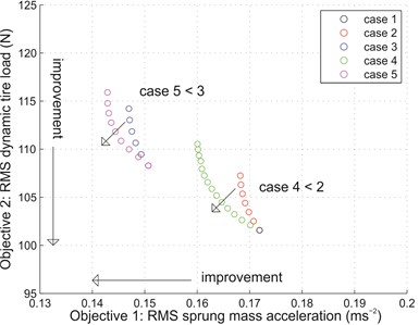
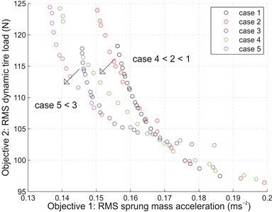
It is already known that ride and road holding ability are two important but conflicting criteria for designing suspensions. A good way to evaluate both criteria simultaneously is to analyze the Pareto front involving the two objectives for a given suspension system, for example as done in an earlier study [20]. Pareto front shows the relationship among multiple design objectives, and contains the set of all Pareto optimal solutions which are non-dominated by other solutions. Fundamentally, a solution is non-dominated and belongs to the Pareto set if there is no other solution that can improve at least one of the objectives without degradation of any other objective [21]. Therefore, specific to this study, a solution is Pareto optimal and forms part of the Pareto front if there is no other solution that can reduce the RMS sprung mass acceleration without increasing RMS dynamic tire load. By identifying the Pareto optimal points from the results, scatter plots showing the Pareto fronts for all cases, considering only inertance as design variable (Fig. 6(a)) and both damping coefficient and inertance as design variables (Fig. 6(b)), were plotted and analyzed.
Before evaluating the effectiveness of using switchable inerter, some points are worth mentioning. Firstly, as shown in Fig. 6(a), for every Pareto front (cases 2 to 5) there is a point that corresponds to minimum attainable RMS sprung mass acceleration. This is the solution that represents optimum inertance which maximizes ride improvement without considering deterioration of the other objective, and is identical to the results showcased in Section 3.1 where only single objective was evaluated. Secondly, case 1 which served as reference is only represented as a single point in Fig. 6(a), as it did not involve optimization of inertance. From the figure, this is also the point of overlapping between Pareto fronts of cases 2 and 4 which represent zero passive and on-state inertances.
Fig. 6Pareto fronts with a) only inertance as design variable and b) both damping coefficient and inertance as design variables
a)
b)
Several interesting observations can be made by analyzing and comparing the Pareto fronts in Fig. 6(a). One can observe that by allowing the inerter to be switchable based on force cancellation strategy, the Pareto optimal sets obtained were better than those with passive inerter. Specifically, case 4 shows an improvement over case 2, while case 5 shows improvement over case 3. This implies that both ride and road holding ability can be improved by the switchable capability of the inerter.
Another comparison made between case 2 and case 3 (or, correspondingly, between case 4 and case 5) revealed some useful information regarding the implementation of force cancellation strategy on switchable damper. When allowed to be varied between the specific maximum and minimum damping coefficients as stated in Section 2.2, the Pareto front shifted (from case 2 to case 3, or from case 4 to case 5) towards the left but upwards. This implied that force cancellation was more beneficial in providing ride improvement than tire road holding improvement. However, it is important to note that this implication is valid only for the specific damping coefficients used in the analysis.
Meanwhile, the Pareto fronts considering both damping coefficient and inertance as design variables are shown in Fig. 6(b). By comparison, the repeated analysis showed the same observations: case 4 showed an improvement over case 2; so did case 5 over case 3. However, by allowing the passive damping coefficient (or, in some cases, the maximum damping coefficient) to be varied together with inertance, additional differences were observed. By comparing Fig. 6(b) to Fig. 6(a), the Pareto fronts (cases 2 to 5) are noticeably wider, indicating greater possibilities of optimal design solutions. Also, for cases 2 and 4 which employed passive damper, the Pareto optimal sets were better than those from Fig. 6(a). Overall, results from Fig. 6 confirms that the switchable inerter is a healthy step superior to its passive counterpart.
4. Conclusions
The implementation of on-off switchable inerter based on force cancellation strategy in vehicle suspensions resulted in solid improvement over ordinary passive suspension in terms of ride comfort. When only ride was concerned, simulations on QVM indicated that suspension systems with switchable inerter managed to reduce the RMS sprung mass acceleration compared to ordinary passive suspension more significantly than suspension systems incorporating passive inerter. Further comparison showed that the ride improvement brought by a switchable inerter is comparable to switchable damper employing the same control strategy. When both sprung mass acceleration and dynamic tire load were considered, the Pareto fronts for cases involving switchable inerter were again superior to those involving passive inerter, showing that the switchable capability of inerter could further improve the ride and tire road holding performance measures achieved by passive parallel inerter which was only slightly better than those of ordinary passive suspension when considering typical passenger vehicle parameters as in this study. Overall, it can be concluded that the on-off switchable inerter has demonstrated fundamentally greater benefits in vertical ride dynamics of passenger vehicle suspension than a passive inerter. Seeing this potential of the switchable inerter, further exploration on the overall ride comfort of a complete full vehicle, considering not just the vertical dynamics, but also the rotational dynamics such as roll and pitch responses, is particularly interesting.
References
-
Gillespie T. D. Fundamentals of Vehicle Dynamics. Society of Automotive Engineers, Warrendale, 1992.
-
Smith M. C. Synthesis of mechanical networks: the inerter. IEEE Transactions on Automatic Control, Vol. 47, Issue 10, 2002, p. 1648-1662.
-
Li C., Liang M., Wang Y., Dong Y. Vibration suppression using two-terminal flywheel. Part II: Application to vehicle passive suspension. Journal of Vibration and Control, Vol. 18, Issue 9, 2012, p. 1353-1365.
-
Wang F. C., Hong M. F., Chen C. W. Building suspensions with inerters. Proceedings of the Institution of Mechanical Engineers, Part C: Journal of Mechanical Engineering Science, Vol. 224, Issue 8, 2010, p. 1605-1616.
-
Wang F. C., Yu C. H., Chang M. L., Hsu M. The performance improvements of train suspension systems with inerters. Proceedings of the 45th IEEE Conference on Decision and Control, 2006, p. 1472-1477.
-
Wang F. C., Liao M. K. The lateral stability of train suspension systems employing inerters. Vehicle System Dynamics, Vol. 48, Issue 5, 2010, p. 619-643.
-
Smith M. C., Wang F. C. Performance benefits in passive vehicle suspensions employing inerters. Vehicle System Dynamics, Vol. 42, Issue 4, 2004, p. 235-257.
-
Soong M. F., Ramli R., Mahadi W. N. L. Vehicle suspensions with parallel inerter: Effectiveness in improving vibration isolation. Journal of Vibroengineering, Vol. 16, Issue 1, 2014, p. 280-289.
-
Zhang X., Ahmadian M., Guo K. On the benefits of semi-active suspensions with inerters. Shock and Vibration, Vol. 19, Issue 3, 2012, p. 257-272.
-
Guglielmino E., Sireteanu T., Stammers C. W., Ghita G., Giuclea M. Semi-active Suspension Control: Improved Vehicle Ride and Road Friendliness. Springer, London, 2008.
-
Li C., Liang M. Characterization and modeling of a novel electro-hydraulic variable two-terminal mass device. Smart Materials and Structures, Vol. 21, Issue 2, 2012, p. 025004.
-
Wang F. C., Hong M. F., Lin T. C. Designing and testing a hydraulic inerter. Proceedings of the Institution of Mechanical Engineers, Part C: Journal of Mechanical Engineering Science, Vol. 225, Issue 1, 2011, p. 66-72.
-
Soong M. F., Ramli R., Mahadi W. N. L. Using gear mechanism in vehicle suspension as a method of altering suspension characteristic. Journal of Vibration and Control, Vol. 21, Issue 11, 2015, p. 2187-2199.
-
Wang F. C., Chan H. A. Mechatronic suspension design and its applications to vehicle suspension control. Proceedings of the 47th IEEE Conference on Decision and Control, 2008, p. 3769-3774.
-
Wang R., Ye Q., Sun Z., Zhou W., Cao Y., Chen L. A study of the hydraulically interconnected inerter-spring-damper suspension system. Mechanics Based Design of Structures and Machines, 2016, p. 1-15, https://doi.org/10.1080/15397734.2016.1235979.
-
Crolla D. A., Whitehead J. P. Vehicle Dynamics, Control and Suspensions. University of Leeds, Leeds, 2003.
-
Sharma K., Crolla D. A., Wilson D. A. Derivation of a control law for a 3 state switchable damper suspension system for improving road vehicle ride characteristics. Proceedings of the International Symposium on Theory of Machines and Mechanisms, 1992.
-
Mechanical Vibration – Road Surface Profiles – Reporting of Measured Data (ISO 8608:1995). International Organization for Standardization, Geneva, 1995.
-
Pires L., Smith M. C., Houghton N. E., McMahon R. A. Design trade-offs for energy regeneration and control in vehicle suspensions. International Journal of Control, Vol. 86, Issue 11, 2013, p. 2022-2034.
-
Scheibe F., Smith M. C. Analytical solutions for optimal ride comfort and tyre grip for passive vehicle suspensions. Vehicle System Dynamics, Vol. 47, Issue 10, 2009, p. 1229-1252.
-
Ngatchou P., Zarei A., El-Sharkawi M. A. Pareto multi objective optimization. Proceedings of the 13th International Conference on Intelligent Systems Application to Power Systems, 2005, p. 84-91.
Cited by
About this article

The authors thank University of Malaya for providing the necessary facilities and other supports that has led to the completion of this research. This work was supported by PPP Research Grant, University of Malaya (Project Number PV051-2011A).
