Abstract
Radial force in implantable two-stage axial flow blood pump (Artificial Heart) is a major factor affecting the operation stability. In order to investigate the transient operation characteristics of two-stage blood pumps, three-dimensional, unsteady numerical simulations were conducted by using the large eddy simulation (LES) model, PISO algorithm based on the sliding mesh technique in Fluent. The performance of the pump was obtained and compared with the experimental results. Besides, the radial force at various monitoring points were acquired; next, they were analyzed in time and frequency domains, respectively. It was demonstrated that the radial force at all the monitoring points changes periodically with time, its number of periods is identical to the number of blades but less affected by the number of guide vane blades, its frequency is close to the blade passing frequency. The frequency of radial force within the impeller increases gradually towards the impeller outlet and approaches the maximum value there, while the variation tendency of the frequency is opposite within the guide vane. The mostly dramatic radial force occurs at the impeller outlet, the main frequency at various monitoring points is almost equal to the impeller passing frequency. The amplitude of radial force coefficient at the monitoring points in the second stage impeller is higher than the first stage impeller. Additionally, the main frequency of radial force in the first stage impeller is different from the second stage guide vane.
1. Introduction
Blood pump is a small pump that can completely or partially replaces heart function and maintains normal body blood circulation. it plays an important role in the treatment of cardiovascular disease and can significantly improve survival rate and the quality of life of patients with severe congestive heart failure [1]. Since the 1980s, the axial flow blood pump benefits from its compact size and easy to control, it gradually becomes the development direction of artificial heart. The hydraulic model of axial flow blood pump is designed based upon the assumption that the flow in both the blade and diffuser is steady and irrelevant, nevertheless, the rotor-stator interaction between blade and diffuser can results in excitation forces under design flow rate and an even stronger forces under off design flow rates [2, 3], as the important component of excitation forces, the hydrodynamic radial forces impair the reliability of blade, shaft and bearings [4, 5]. The hydrodynamic forces applied on blade are difficult to solved with theoretic method [6, 7], Zhu et al obtained pump head flow characteristics and the Efficiency-Q curves at various rotating speeds, it also shown that the Reynolds shear stress is the dominant force to damage blood [8].
Yasuda et al researched the relationship between static pressure and shear forces of blood pump [9]. Other researchers such as Agostinelli et al. were the first to investigate the lateral excitation on an blade in a vane-less volute. The fluid field in the blade passage of a certain type of blood pump was numerical simulated by computer aided solving the three dimensional Navier-Stokes equations by Baoning Zhang [10]. Cheng Li built a CFD model of mixed-flow water-jet pump, and the results show a good quantitative agreement with experimental data, this proved the validity of CFD model used in hydrodynamic radial forces prediction [11].
Kruger et al. did CFD analysis of vertical mixed-pump installed in a sump, the vortexes distribution in sump around pump inlet and hydrodynamic radial force applied on blade were agreed with experiment results [12]. It is concluded that CFD simulation method is a valid mean for pump's transient hydrodynamic force prediction and analysis. This paper present a numerical investigation on hydrodynamic radial force of two-stage axial flow blood pump under several operational conditions, meanwhile, the flow field distribution and pressure fluctuation were investigated and explain how the flow pattern and rotor-stator interaction phenomena changed at part-load conditions, and finally, some meaningful conclusions were drawn.
2. Model test rig
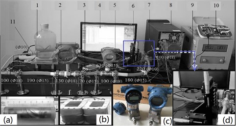
In order to verify the simulation results, the experiment system of the research pump was established in Shanghai University. The schematic arrangements of the test rig facilities are shown in Fig. 1. and photo of the pump test are shown in Fig. 2. The motor is able to drive the pump to the designed rotation speed of 7000 r/min. Two pressure transmitters are installed in the test loop to measure the inlet and outlet pressure respectively. And the measurement errors of the two pressure transmitters are both 0.1 %. A gate valve is installed near the outlet of the loop to adjust the flow rate of the pump. The turbine flow meter is mounted behind the pressure transmitter near the gate valve to measure the volumetric flow rate of the pump. And the uncertainty of the turbine flow meter is 0.1 %. Besides, the control pulse was output to the windings of the electromagnet by the SCM controlled circuit, and the alternating magnetic field was obtained. Thus, the permanent magnet rotor which had a certain coupling distance to the electromagnet can be forced to rotate by the alternating magnetic field. At last, aqueous Xanthan gum is a non-Newtonian fluid which displays remarkable shear thinning behavior and can be used as a blood analog fluid. The experimental results show that, at 30 °C, Xanthan gum solutions with concentration of 0.4 wt.‰ will match human blood best in rheological properties [13].
Fig. 1The sketch of test rig
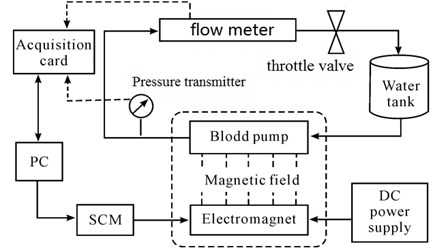
Fig. 2The test rig: 1. Water tank; 2. Flow meter; 3. 12 V switching power supply; 4. Monitoring interface; 5. Pressure transmitter; 6. Blood pump; 7. Electromagnet and mobile platform; 8. PC; 9. DC power supply; 10. SCM control system; 11. Throttle valve; a) Blood pump; b) Iron core; c) Pressure transmitter; d) Electromagnet and mobile platform
3. Mathematical model
It is theoretically possible to directly resolve the whole spectrum of turbulent scales using an approach known as direct numerical simulation (DNS). DNS is not, however, feasible for practical engineering problems. Adding to the computational cost is the fact that the simulation will be a transient one with very small time steps, since the temporal resolution requirements are governed by the dissipating scales, rather than the mean flow or the energy containing eddies. The Reynolds-averaged Navier-Stokes (RANS) equations represent transport equations for the mean flow quantities only, with all the scales of the turbulence being modeled. The approach of permitting a solution for the mean flow variables greatly reduces the computational effort. If the mean flow is steady, the governing equations will not contain time derivatives and a steady-state solution can be obtained economically. A computational advantage is seen even in transient situations, since the time step will be determined by the global unsteadiness in the mean flow rather than by the turbulence. Conceptually, large eddy simulation (LES) is situated somewhere between DNS and the RANS approach. Basically, large eddies are resolved directly in LES, while small eddies are modeled. The following sections give details of the governing equations for LES, present the two options for modeling the sub-grid scale stresses and discuss the relevant boundary conditions.
3.1. Governing equations
The governing equations employed for LES are obtained by filtering the time-dependent Navier-S tokes equations in either Fourier (wave number) space or configuration (physical) space. The filtering process effectively filters out eddies w hose scales are smaller than the filter width or grid spacing used in the computations. The resulting equations thus govern the dynamics of large eddies. Filtering the incompressible Navier-Stokes equations, one obtains [14]:
where, is the subgrid-scale stress defined by:
It is obvious that the major difference involved in these equations is that the dependent variables are now filtered quantities rather than mean quantities, and the expressions for the turbulent stresses differ.
3.2. Boundary conditions for the LES model
The stochastic components of the flow at the velocity-specified inlet boundaries are accounted for by superposing random perturbations on individual velocity components as:
where, is the intensity of the fluctuation, Gaussian random number satisfying 0, 1. When the mesh is fine enough to resolve the laminar sub-layer, the wall shear stress is obtained from the laminar stress-strain relationship:
If the mesh is too coarse to resolve the laminar sublayer, it is assumed that the centric of the wall adjacent cell falls within the logarithmic region of the boundary layer, and the law of the wall is employed:
where, is the von Kármán constant and 9.793.
4. Numerical simulation
4.1. Physical model
The parameters of the blood pump at the design operational condition as follow: Flow rate 0.1055 kg/s, nominal head 120 mmHg, rotational speed 7000 r/min, shaft frequency /60 116.7 Hz. As is shown in Fig. 3, the pump assembly mainly includes first-blade, second-blade, guide vane, inlet pipe, outlet pipe, magnetic bearing rotor/stator, brushless machine rotor/stator, etc. [15]. The main geometric parameters of the test pump are listed in Table 1.
The three-dimensional physical model of the hydraulic turbine is shown in Fig. 4. The lengths of outlet pipe and inlet pipe are extended to 3 times the pipe diameter to increase the simulation accurately [16].
Fig. 3Cross section of test pump
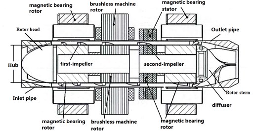
Table 1Geometric dimension of the pump
Parameters | Values |
Blade outer diameter | 18 mm |
Hub diameter | 10 mm |
The first stage blade length | 22 mm |
Rotor stern length | 10 mm |
Rotor head length | 14 mm |
Guide vane length | 15 mm |
Secondary blade length | 12 mm |
4.2. Grid formation
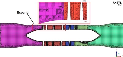
The grid is generated using the geometry preprocessor of the ICEM program. As the trailing edges of blades and diffuser are all quite thin, the size of grids can’t be uniform. To form dense grids near the blades and diffuser trailing edge, densification technique is utilized in some local blades and diffuser portion. The mesh of 2.88 million cells consists of a hybrid grid with prismatic and Hex-core cells (see Fig. 5).
Fig. 4Physical model of two stage axial flow blood pump
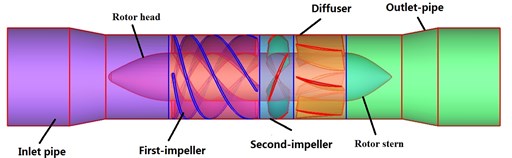
Fig. 5Cross section of mesh
4.3. Validation of grid independence
In order to check the influence of the grid on the results, meshes with different cell numbers are tested, the test results are shown in Table 2. It indicates that Grid B and Grid C have the same pressure head nearly. But Grid C needs more computation resource and time because of more cells. Finally, the Grid B is the best one, the quality of the worst cell is bigger than 0.25, which satisfies the solver.
Table 2Grid independence analysis
First stage (106) | Second stage (106) | Guide vane (106) | Inlet, Outlet (106) | Amount (106) | Pressure Head (mmHg) | |
Grid A | 1.05 | 0.42 | 0.51 | 0.31 | 2.29 | 121.5 |
Grid B | 1.28 | 0.55 | 0.67 | 0.38 | 2.88 | 133.3 |
Grid C | 2 | 1.1 | 0.82 | 0.55 | 4.47 | 134 |
4.4. Boundary and initial conditions
Inlet boundary condition: assume that inlet velocity is uniform at axis direction and its value equals to ratio of flow rate and inlet area:
where, is the flow rate, is the pump inlet diameter.
Outlet boundary condition: “outflow” is implemented on pump outlet and flow rate weighting is set to be 1.
Wall boundary condition: No slip condition is enforced on wall surface and enhanced wall function is applied to adjacent region, the near wall value should less than 5. All the values of the model surfaces met this requirement and a 8 level grid is generated in the inlet, outlet, blades and guide vane area [17]. This study utilized the ANSYS FLUENT 17 commercial code to solve the Large Eddy Simulation (LES) equations for the unsteady flow in the computational domain [18]. The PISO algorithm and Bounded Second Order Implicit transient formulation are selected to solve pressure-velocity coupling for steady and unsteady simulation respectively. The initial values must be obtained based on - model and then the unsteady flow will be treated in terms of LES model, the computational time for turbulent flow simulations will be greatly reduced. In addition, interfaces between impeller and other parts are set to be “sliding mesh model (SMM)” [19, 20] while other interfaces remains to be “General connection”. Time-step for unsteady simulations is given 2.234e-5 s, which namely means the impeller rotates for 1 degree during 1 time-step. Convergence precision of residuals is 10–4.
4.5. Prediction algorithm
Head is calculated by the following formula:
where is the total pressure at volute outlet, is the total pressure at impeller inlet, is the density of liquid, is the gravity acceleration.
Hydraulic efficiency is calculated as:
where is the impeller torque, is the angle velocity. Volume efficiency is calculated as [8]:
Total efficiency is calculated as:
where is the water power and , is the disk friction loss and its calculation method is in Ref. [21].
In unsteady analysis, to obtain the change law of the blade radial force with time, we sampling the radial force of blade and blade hub. The radial force coefficient is calculated by the following formula:
where is total pressure at monitor points, is reference pressure, is the density of liquid (1055 kg/m3), is the circular velocity of the blade out. The radial force is a vector which changed with time, in order to study its varying characteristic, we decompose it along the radial plane and . So, we get the radial force coefficient , , . Obviously, the varying characteristic of dynamic radial force could be obtained.
4.6. Selection of turbulence model
Turbulence model selection is a crucial part for numerical simulation because inappropriate turbulence model may leads to error result. Therefore, the Standard -, RNG -, LES turbulence models have been selected to simulate the interior flow of the pump. Comparing with the data obtained from the experiment, the results of the three turbulence models above are listed in Table 3. It indicates the results calculated by LES are closest to the experiment data, which means the LES turbulence model is appropriated to perform the simulations in this paper.
Table 3The comparison of different models
Head / mmHg | Head error / % | Efficiency / % | Efficiency error / % | |
Standard - | 125.21 | 4.23 | 15 | 0.91 |
RNG - | 130.26 | 7.14 | 18 | 1.32 |
LES | 141.46 | 7.23 | 25 | 1.53 |
5. Validation of CFD results
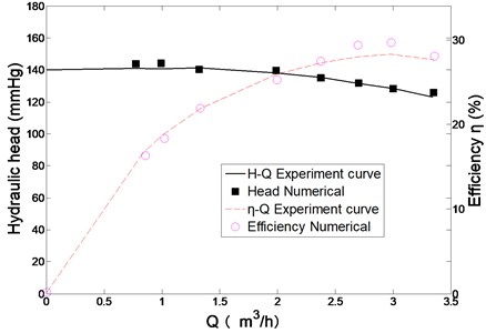
Fig. 6 gives the curves of numerical and experimental results. As is shown in the figure, numerical performance curves are in good agreement with experimental results. For the range of 0.85 m3/h-3.36 m3/h, the relative errors of head and efficiency are less than 5 %. This comparison between numerical and experimental results proves the CFD method could predict the pump performance with acceptable accuracy.
Fig. 6Comparison of numerical and experimental results
6. Prediction results and analysis
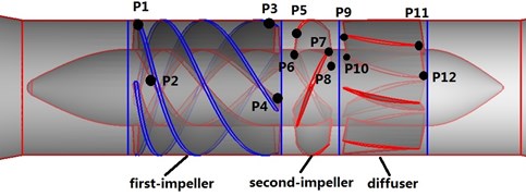
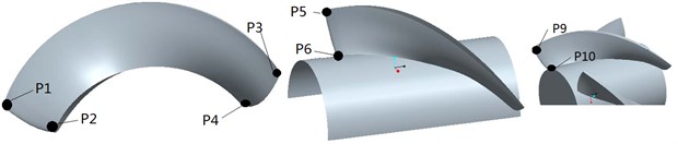
In order to investigate the radial force details result from rotor-stator interaction, the pressure amplitudes of points - (as shown in Fig. 7) under different flow rates were monitored and analyzed by Fast Fourier Transform (FFT) method [22]. , located at first stage blade inlet while , located at first stage blade outlet. , located at second stage blade inlet; , located at second stage blade outlet; , located at guide vane inlet, , located at guide vane outlet.
6.1. Hydrodynamic radial force in time domain and frequency domain at monitoring points in first stage
The direction and magnitude of transient hydrodynamic radial forces applied on impeller change with impeller rotation all the time, the transient dynamic forces data could be calculated through the unsteady CFD simulation. The rotary speed of the rotor is 7000 r/min that means the rotational frequency of rotor is 116.67 Hz, the rotation period of the rotor is 0.0086 s. The pressure peak appears three times during a rotation period of rotor, it is equivalent to the number of blades.
Fig. 7Monitoring points specified in blood pump
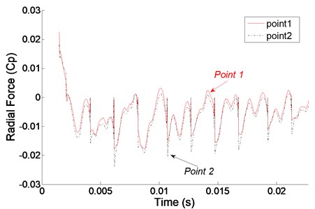
In order to observe the radial force conveniently, the flow rate sets to 3 m3/h. Fig. 8 gives the time domain at monitoring points in first blade inlet and outlet. It can be seen that the radial force at all the monitoring points changes periodically with time, the radial force of , , , are 0.0035, 0.0022, 0.0121, 0.0052, respectively. Apparently, the radial force of and are higher than and , which means the larger radial force occurs at blade outlet. Besides, the time of wave appears to crests earlier than , the time of wave appears to amplitude earlier than , which illustrates the radial force signal comes from impeller outlet and decreases gradually along with the transmit to second stage.
Fig. 8Radial force in time domain at monitoring points in first stage
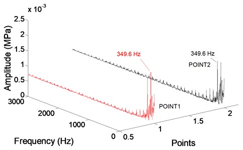
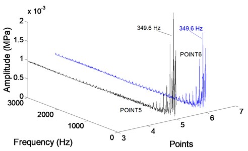
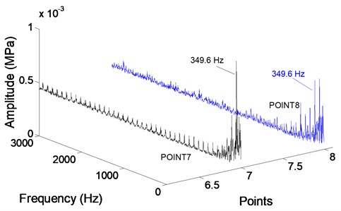
A fast Fourier transform (FFT) then applied to obtain the detailed radial force distribution. Fig. 9 gives the radial force in frequency spectrum of to . Every point in graph represents the dominant frequency is 349.6 Hz, which is 3 times of the rotational frequency and equal to blade passing frequency 350 Hz, means the radial force in first stage is determined by blade passing frequency.
Fig. 9Radial force in frequency domain at monitoring points in first stage
6.2. Hydrodynamic radial force in time domain and frequency domain at monitoring points in second stage
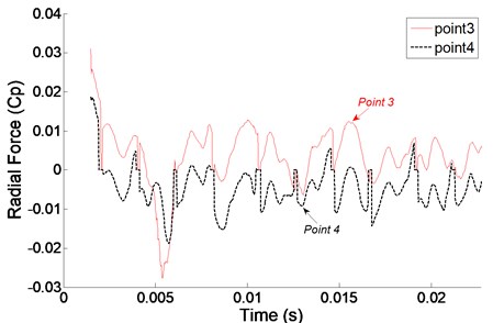
Fig. 10 shows the time domain at monitoring points in second stage inlet and outlet. Similar to the first stage, the radial force at all the monitoring points also changes periodically with time in the second stage.
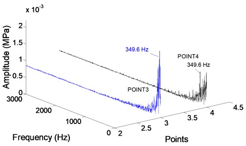
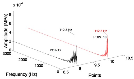
As shown in the Fig. 11, the frequency of radial force within the blade inlet increases gradually towards the impeller outlet and approaches the maximum value there, while the variation tendency of the frequency is opposite within the guide vane. radial force at all the monitoring points are larger than in the first stage, which explains that the second stage is influenced by rotor-stator interaction itself but also relevant to the rotor-stator interaction of the former stage, the signals adding together here.
The main frequency of monitoring point 9 and point 10 at guide vane inlet are 112.3 Hz and 43.95 Hz, respectively. The main frequency of radial force in the first stage impeller is different from the second stage guide vane, the main reason for it is the point 9 and point 10 are affected by first stage and second stage at the same time possibly; It can be sure that the impeller outlet exists vortex free motion, the most intense motion happens at impeller outlet, the main frequency of monitoring points there are all 349.6 Hz, which is equal to blade passing frequency.
Fig. 10Radial force in time domain at monitoring points in second stage
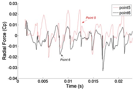
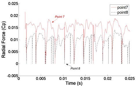
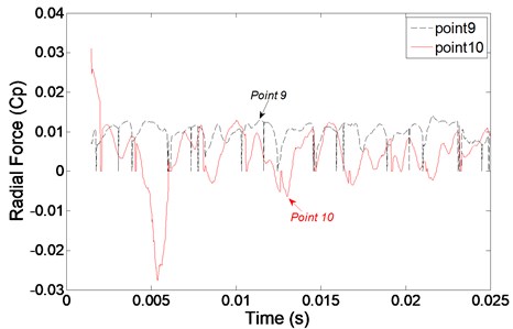
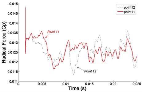
Fig. 11Radial force in frequency domain at monitoring points in second stage
7. Conclusions
In the article, a two stage axial-flow blood pump is used as the object of study. The computational and experimental analysis of the results could be summarized.
1) The performance of blood pump can be accurately predicted by CFD simulation based on appropriated setups, the maximum head prediction error is less than 5 %.
2) The main frequency of radial force in the first and the second stage impeller increases gradually towards the impeller outlet and approaches the maximum value there, while the variation tendency of the frequency is opposite within the guide vane. Besides the maximum radial force appears at impeller outlet and guide vane inlet, which effect the operation stability of pump.
3) Radial force at all the monitoring points in the second stage is larger than in the first stage, which explains that the second stage is not only influenced by rotor-stator interaction itself but also relevant to the rotor-stator interaction of the former stage, the signals adding together here; radial force signal comes from impeller outlet and decreases gradually along with the transmit to second stage.
4) The mostly dramatic radial force occurs at the impeller outlet, the main frequency 349.6 Hz at various monitoring points is almost equal to the blade passing frequency. The amplitude of radial force coefficient at the monitoring points in the second stage impeller is higher than the first stage impeller. Additionally, the main frequency of radial force 349.6 Hz in the first stage impeller is different from the second stage guide vane 112.3 Hz and 43.95 Hz.
5) The above results show that the rotor-stator interaction of the both first stage and the second stage affects in a big way to the radial force and an appropriate impeller outlet angle and the impeller outlet flow of the pump should be given more attention.
References
-
Boehning F., Timms D. L., Amaral F., et al. Evaluation of hydraulic radial forces on the impeller by the volute in a centrifugal rotary blood pump. Artificial Organs, Vol. 35, Issue 8, 2011, p. 818-825.
-
Thomas A. L. Reduction of Unsteady Rotor-stator Interaction Using Trailing Edge Blowing. Virginia Polytechnic Institute, Blacksburg, 1997.
-
Jacquet R. G., Torkhani M. Rotor to stator contacts in turbo machines. Review and application, Mechanical Systems and Signal Processing, Vol. 40, Issue 2, 2013, p. 401-420.
-
Rodriguez C., Egusquiza E. Frequencies in the vibration induced by the rotor stator interaction in a centrifugal pump turbine. Journal of Fluids Engineering, Vol. 129, Issue 11, 2007, p. 1428-1435.
-
Zhang M., Tsukamoto H. Unsteady hydrodynamic forces due to rotor-stator interaction on a diffuser pump with identical number of vanes on the impeller and diffuser. Journal of Fluids Engineering, VVol. 127, Issue 4, 2005, p. 743-751.
-
Agostinelli A., Nobles D., Mockridge C. R. An experimental investigation of radial thrust in centrifugal pumps. Journal of Engineering for Gas Turbines and Power, Vol. 82, Issue 2, 1960, p. 120-125.
-
Iversen H. W., Rolling R. E., Carlson J. Volute pressure distribution, radial force on the impeller, and volute mixing losses of a radial flow centrifugal pump. Journal of Fluids Engineering, Vol. 82, Issue 2, 1960, p. 136-143.
-
Zhu X. R., Zhang M. Y., Zhang G. G., et al. Numerical investigation on hydrodynamics and biocompatibility of a magnetically suspended axial blood pump. ASAIO Journal, Vol. 52, Issue 6, 2006, p. 624-629.
-
Yasuda T., Shi Mokasa K., Funakubo A. Influence of static pressure to red blood cell damage under shear rate condition. ASAIO Journal, Vol. 46, Issue 2, 2000, p. 227-236.
-
Zhang B. N., Zhang Y. J., Wu Y. L., et al. Analysis of flow field in an artificial blood pump with CFD. Chinese Journal of Biomedical Engineering, Vol. 21, Issue 1, 2002, p. 41-45.
-
Cheng L., Bart P. M. Radial force of water-jet propulsion mixed-flow pump. Journal of Drainage and Irrigation Machinery Engineering, Vol. 30, Issue 6, 2012, p. 636-640.
-
Kruger S., Bouziad Y. A., Maurer W. Pump sump CFD for vertical pump design. Proceedings of the ASME: Fluids Engineering Division Summer Conference, Colorado, USA, 2009, p. 191-198.
-
Zhang G. G., Zhang M. Y., Zhu X. R. Experimental investigation of rheological properties of blood and Xanthan gum solutions as a blood analog fluid. Journal of Experiments in Fluid Mechanics, Vol. 21, Issue 2, 2007, p. 41-45.
-
Bui T. A parallel finite-volume algorithm for large-eddy simulation of turbulent flows. Computer and Fluids, Vol. 29, 2000, p. 877-915.
-
Akamatsu T., Tsukiya T. Development of a centrifugal blood pump with magnetically suspended impeller and the related fluid mechanical problems. Indian Academy of Sciences, Vol. 23, Issue 5, 1998, p. 597-603.
-
Brennen C. E. Hydrodynamics of Pumps. Cambridge University Press, New York, 2011.
-
Shi W. D., Zou P. P., Zhang D. D., et al. Unsteady flow pressure fluctuation of high specific speed mixed-flow pump. Transactions of the Chinese Society of Agricultural Engineering, Vol. 27, Issue 4, 2011, p. 147-152.
-
ANSYS Fluent 16.0 Theory Guide. Ansys Inc., Canonsburg, PA, 2015.
-
Wang F. J., Zhang L., Zhang Z. M. Analysis on pressure fluctuation of unsteady flow in axial-flow pump. Journal of Hydraulic Engineering, Vol. 38, Issue 8, 2007, p. 1003-1009.
-
Yao J., Shi W. D., Wu S. Q., et al. Numerical calculation and experiment on pressure fluctuation in axial flow pump. Transactions of the Chinese Society for Agricultural Machinery, Vol. 44, Issue 1, 2013, p. 119-124.
-
Tan M. G. Theory and Software Development on Characteristics Prediction of Centrifugal Pumps. Jiangsu University, Zhenjiang, 2006.
-
Jin S. B., Wang Y. S., Chang S. P., et al. Pressure fluctuation of interior flow in mixed-flow pump Transactions of the Chinese Society for Agricultural Machinery, Vol. 44, Issue 3, 2013, p. 64-68.
Cited by
About this article

The authors gratefully acknowledge the support from National Natural Science Foundation of China (Grant No. 51574161).
