Abstract
This paper explored the blade-bending, disk-transverse and shaft-torsion coupling vibrations phenomenon of a multi flexible disc rotor system, whose blades subsystem was grouped with spring. Being different from the author’s previous researches, here we used two methods: one is the assumed mode method (AMM) and the other is the finite element method (FEM), the proposed former one is main, and the latter one is complementary. Then compared the two results generated from them. According to the authors’ previous definition, a flexible disc rotor system displays three coupling vibrations’ types, inter-blade (BB), shaft-disk-blade (SDB) and disk-blade (DB) modes. In this paper, the authors additionally defined two new types, which were called lacing wires-blade (LB) and lacing wires-disk-blade (LDB) mode. The system change rules of natural frequencies and that of mode shapes would be discussed. Some interesting results are shown in this paper. Firstly, the author pointed out the change rules of the mode shapes and natural frequencies by using the AMM and FEM (including three kinds of softwares). Secondly, numerical calculation results also showed that the distance of disk, the disk with flexible, the constant of spring, and location of spring four phenomena would affect the natural frequencies.
1. Introduction
When the rotating structure is running, the vibration could cause fatigue damage, and even lead to serious casualties. In recent years, the steam power plants are improving the operation efficiency, and a large number of high pressure steam turbines are used. Because of the corresponding increases in the speed of the turbine, the safety requirements of the turbine are also increasing. Even, the aviation turbines and propellers are involved in the flight safety, their reliability requirements are more stringent.
Researches of single subsystem in the rotor system are less and less in this century. The more complex system such as disk-blade or shaft-disk has been focused and studied. The vibration characteristics of the disk-blade and shaft-disk were studied and the coupling affects subsystems were described. Sino et al. [1] used three kinds theories, such as the equivalent modulus beam theory and so on, to be solved the natural frequency and the threshold value of the dynamic instability of the internal damping rotating composite shaft. Turhan and Bulut [2] investigated the coupling effects between shaft-torsion and blade-bending vibrations in turbo machinery. They used uniform Euler-Bernouilli beams to simulate blade for an idealized model. Villa et al. [3] used harmonic balance method to explore a flexible rotor’s nonlinear dynamics problem. The authors [4-6] ever explored the coupled vibration phenomena of a single flexible disk rotor system with a mistuned blade length, a cracked blade and a disorder angle blade. After 2010, some researches such as Yim and Ryu [7] investigated the overhung flexible rotors, and explored the dynamic stability questions. Zolkiewski [8] investigated the damped vibrations problem of beams fixed on the rotational disk. Bashmal et. al [9] used Rayleigh-Ritz method to explored an annular disk with point elastic support problem. They found that the addition of point clamped support causes bifurcation. Sinou & Faverjon [10] took advantage of the FEM and Harmonic Balance Method to investigate the effects of a transverse crack in a rotating shaft. Chouksey [11] adopted analytical method to explore the influence of the damping and fluid film forces on the modal characteristics of the rotor system. Collins et al. [12] developed a CFD and CSD simulation method. An approximate model is established to measure the vibration efficiency and high precision of the rotor. Avramov and Filipkovskii [13] explored a nonlinear multi disc rotor system. The model considers the effects of the elastic properties of the disc and the shaft when the effects are influenced by the moment.
The turbine disc blades are usually grouped in packets by lacing wire or a shroud to make the blades be a ring closure structure. The deformation and vibration of the shaft, the disk, and the blades are always encountered. Numerous researches have been published on the individual vibrations of the shaft, disk blades and lacing. Lately, Kwon and Yoo [14] used the HDVM to explore the localization of vibration with random mistuned. Lee et. al. [15] used SWM to discuss that the starting point is a set the normal pattern of blade discs, the rate will be all forms of blade and disk, and the shroud of the elastic coupling. Zinkovskii and Kruglii [16] used FEM to investigate the effect of possible identity violations of contact interaction between shrouds on the static stress state characteristics of blades. Pust and Pesek [17] investigated the response of circular bladed disk with shrouds. They found that the high of resonance peaks is strongly affected by the nonproportional distribution of damping. Luo [18] utilized finite element and analytical method to investigate blades with grouped in rotating disc to explore the relationship of natural frequencies, nodal diameters and blade stiffness. Vantadori et al. [19] created the Francis rotor system that welded connections between band and blade. They are proposed to improve the stress intensity factor (SIF) method in the computations. The author’s previous researches [20-22] only used assume mode method to analyze the influence on coupling vibrations among shaft-torsion and blade-bending coupling vibrations of a rigid single/multi disk(s) rotor system with grouped blades.
This paper will explore the coupling behavior among shaft-torsion, disk-bending, blade-bending and the blades packeted by lacing wire. In this kind of system, the disks are considered to be flexible, the blades are modeled to be of Eular type with stagger angle, the lacing wire is assumed as massless spring. When using the finite element method to analyze it, we employed three kinds of softwares, including ANSYS, Nastarn and Hyperworks. Then discuss the system change rule of natural frequencies and mode shapes. This paper aims to provide a qualitative and quantitative overview of a multi flexible disc rotor system. Based on the authors previous researches [4-6] and [20-22] which only used AMM, the authors additionally used FEM to compare and add some interesting results.
2. Theoretical analysis
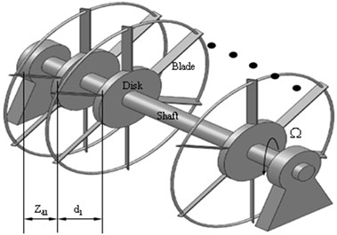
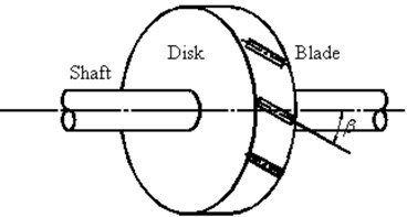
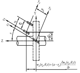
A typical rotor system is shown in Fig. 1. The system includes four subsystems, shaft, multi flexible disc, blades and the blades packeted by spring. The blades have staggle angle. denotes the 1st distance of disk, and denotes two disks spacing distance.
The shaft-disk subsystem torsion energies equations are [4]:
where denotes the displacement of torsional in a rotating frame; , and are the length of shaft, polar moment of inertia, and rigidity of torsion; denotes the polar moment of inertia of disk. The upper “dot” is the time derivative and subscripts and are appointed for disk and shaft.
Fig. 1a) A typical multi-disks rotor system with grouped blade, b) the staggle angle
a)
b)
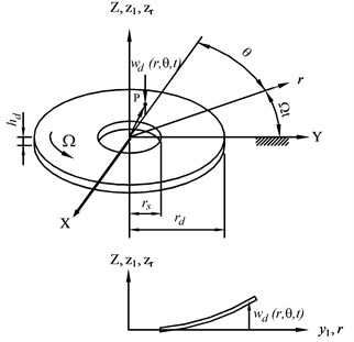
Fig. 2 shows a disk, fixed inside and free outside, rotating at a constant speed . and are the inner and outer radii of disk, and denotes the thickness of disk.
Fig. 2The coordinates and geometry of the rotating disk
The disk’s transverse vibration energies equations are [4]:
where denotes the transverse displacement of disk; is the Laplacian; denotes the bending rigidity; and are circumferential directions and the initial stresses in the radial due to . The follow is the terms:
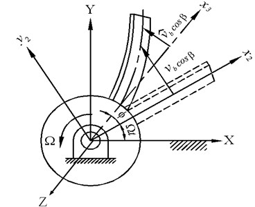
Fig. 3 is shown as a rotating cantilevered blade onto a flexible disk with a stagger angle . The coordinate system is the inertia frame; frame rotates at a constant speed . frame rotates a staggle angle relative to frame, and frame is clamped to the root of blade.
Fig. 3Blade’s deformation and coordinate builds
The blade’s kinetic and strain energies equations are [4]:
where and denotes the transverse displacements in and directions. denotes the area moment of inertia about the axis, and denotes the polar moment of inertia.
The total blade’s displacements and , are the shaft’s torsion displacement , the disk’s transverse displacement of disk , and the blade’s bending displacement . The kinematic relations between these displacements are:
A spring connecting two blades is assumed as massless with stiffness . The energy equation is [21]:
where is the blade’s connecting position.
The AMM is used to discretize the continuous system:
where , , denoted the mode shapes of a torsion shaft, transverse disk, and bending blade.
, , , are the participation factors. , , are subscripts of the corresponding subsystems, are the number of modes seemed suit for required accuracy. The terms are good for yield accuracy up to 10-5 Hz in this paper. These modes are:
where is the disk’s radial function and is chosen the beam function:
is a beam function for blade with:
The above equations are transformed into the expression of energy and employment of the Lagrange equations yields the following discretizated equations of motion in matrix notation as:
where , get from the Coriolis effect, induces natural frequencies bifurcation. Note, is nonzero, when the disk is flexible. So, the frequency bifurcates due to the flexible disk. is observed from the elastic deflection at low rotational speed. is the stiffness form rotation due to initial stress resulted. The term , observed from the rotation of the rotor, softening it becomes very obvious at high speed. It is also important to the effect of rotor stability. is gotten from spring. The matrices , , , , , are shown in Appendix.
are the dimensions of the above matrices, where and is the blade’s and disk’s numbers. The items of the above matrices are shown in the Appendix. is a generalized vector:
Free vibration analysis in an ordinary way, it is assumed the solution is of the form with the undetermined coefficient vector and is the eigenvalue.
3. Finite element methods
The finite element method employed ANSYS, Nastran and Hyperworks softwares to simulate rotor system. Table 1, whose parameters are used in the AMM and FEM, gives the material and geometric properties. Fig. 4 shows a typical finite element mesh. The element types of subsystem were changed for many times, which produced different frequency results, the better ones are selected as follow. Whether by ANSYS, Nastran or by Hyperworks, the better is that the shaft and disks are divided into 3D hexahedral solid elements, the lacing wires used spring elements. Differently, by ANSYS, the blades are divided into 3D tetrahedral solid elements, while by Hyperworks, the blades used 2D shell elements, and by Nastran, the blades are divided into 3D hexahedral solid elements. After testing for many times, the number of elements and nodes are given as follow. One disk rotor system used 75,000 nodes and 65,000 elements, two disks rotor system used 115,000 nodes and 100,000 elements and three disks rotor system used 155,000 nodes and 130,000 elements. But, there are ±10 % errors used in different situation. It is important to note the boundary condition: we assumed that the system is torsional shaft of fixed-free, transverse disk of clamped-free and bending blade of fixed-free.
Table 1Material and geometric properties
Shaft | Density | 7850 kg/m3 |
Shear modulus | 75 GPa | |
Shaft length | 0.6 m | |
Radius | 0.04 m | |
Disk | Density | 7850 kg/m3 |
Young’s modulus | 200 GPa | |
Location | 0.3 m | |
Outer radius | 0.2 m | |
Thickness | 0.03 m | |
Poisson’s ratio | 0.3 | |
Blade | Density | 7850 kg/m3 |
Young’s modulus | 200 GPa | |
Blade outer end | 0.4 m | |
Cross-section | 1.2×10⁻⁴ m2 | |
Area moment of inertia | 1.92×10⁻⁹ m2 | |
Staggle angle | 30o | |
Lacing wire | Stiffness | 0~104 |
Position | 0.005~1 |
4. Numerical results
To be dimensional independence, all numerical results are normalized with respect to the 1st order natural frequency of the cantilever blade, i.e., , and ; the distance of disk, . Table 2 lists natural frequencies of subsystem on coupling vibration. These frequencies are used as the numerical results for interpretation and verification.
Fig. 4A typical finite element mesh of a multi-disks rotor system with grouped blade
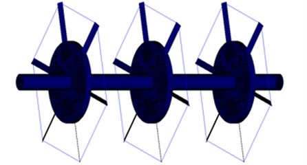
Table 2Natural frequencies (Hz) of subsystem
Component’s n.f. | |||
Shaft-disk (w/o blades) | 207.418 | 2645.690 | 5267.204 |
Disk (shaft rigid) | 921.227 | 974.922 | 1205.039 |
Clamped blade (shaft-disk rigid) | 81.538 | 510.99 | 1430.788 |
Here, is the spring location. Its range is from blade root (0) to blade tip (1), Tables 2 to 5 and Figs. 5 to 14 were described at no rotation . The reasons are that the boundary condition of the shaft torsion vibration is fixed-free. If boundary is different, the selected modes will be changed as well. The modes of a rotating rotor are the traveling modes of its non-rotating modes.
Table 3The first six modes of natural frequencies (Hz) of a flexible disk and five-blades by four methods
Mode | FEM (ANSYS) | Error (%) | FEM (Hyperworks) | Error (%) |
1 (SDB) | 81.020 | 0.159 | 76.4 | –5.55 |
1 (DB) | 81.615 | 0.237 | 77.12 | –5.28 |
1 (DB) | 81.631 | 0.171 | 78.35 | –3.86 |
1 (BB) | 81.670 | 0.161 | 79.66 | –2.30 |
1 (BB) | 81.671 | 0.163 | 79.89 | –2.02 |
1 (SDB) | 203.250 | 0.237 | 270.96 | 33.62 |
Mode | FEM (Nastran) | Error (%) | AMM | |
1 (SDB) | 73.77 | –8.80 | 80.891 | |
1 (DB) | 75.86 | –6.83 | 81.422 | |
1 (DB) | 76.50 | –6.13 | 81.492 | |
1 (BB) | 78.59 | –3.62 | 81.538 | |
1 (BB) | 78.83 | –3.32 | 81.538 | |
1(SDB) | 195.20 | –3.73 | 202.777 |
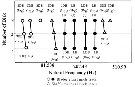
Tables 3 and Table 4 are the first six/seven modes of natural frequencies of a flexible disk and five-/six- blades by two methods. For a flexible disk and five-blade system [4], the coupling modes could be displayed in three groups, the shaft-disk-blade (SDB), disk-blade (DB) and blade-blade (BB). The BB repeated modes were of and for even and odd number blades. 1 to 1modes belong to one group which led by the blade’s 1st mode. mode is led by the shaft’s 1st mode. From Table 3 and Table 4, we observe some results as follow. Firstly, the errors are less than 1 % when using ANSYS. Second, the errors are between –2 % to –9 % when using Nastarn. But, using Hyperworks, the errors led by the blades’ first mode are between –2 % to –6 %, and the errors led by the shaft’s 1st mode reached to 33.62 % (5 blades) or 32.61 % (6 blades). In other words, the result accuracy using ANSYS is better than using Nastarn and Hyperworks. So, the following case study, we only used ANSYS in finite element method. Lastly, the frequency numbers led by the blade’s 1st mode are and that led by the shaft’s 1st mode is 1 (one), this result is conformed to the author’s previous research by assumed mode method.
Table 4The first seven modes of natural frequencies (Hz) of a flexible disk and six-blades by four methods
Mode | FEM (ANSYS) | Error (%) | FEM (Hyperworks) | Error (%) |
1 (SDB) | 81.380 | 0.755 | 76.59 | –5.18 |
1 (DB) | 81.572 | 0.183 | 76.72 | –5.78 |
1(DB) | 81.575 | 0.168 | 76.91 | –3.86 |
1 (DB) | 81.634 | 0.169 | 77.17 | –5.56 |
1 (BB) | 81.668 | 0.159 | 77.28 | –5.22 |
1 (BB) | 81.669 | 0.161 | 77.35 | –5.15 |
1 (SDB) | 203.540 | 0.802 | 267.77 | 32.61 |
Mode | FEM (Nastran) | Error (%) | AMM | |
1 (SDB) | 75.23 | –6.86 | 80.770 | |
1 (DB) | 75.45 | –7.34 | 81.423 | |
1(DB) | 76.04 | –6.63 | 81.438 | |
1 (DB) | 76.26 | –6.42 | 81.496 | |
1 (BB) | 78.85 | –3.30 | 81.538 | |
1 (BB) | 79.27 | –2.78 | 81.538 | |
1 (SDB) | 193.79 | –4.03 | 201.921 |
Fig. 5 shows the modes led by the blade’s 1st mode in a flexible-disk and six-blades rotor by AMM and ANSYS. The - figure displays the torsion displacement of shaft. The deflections of disk and blade are illustrated in the diagrams as follow. The mode type and the natural frequency are indicated on each plot’s upper right and left. Fig. 5(a) shows the modes by AMM and Fig. 5(b) shows the modes by ANSYS. After comparing the results, the authors sum up some phenomena. The most important one is that all results could match both by AMM and by ANSYS. There is little difference among the modes with these two methods, the author explains as follow. First, the frequency numbers led by the blade’s 1st mode is and that led by the shaft’s 1st mode is 1 (one), which is conformed to the author's previous research. Second, when using assumed mode method, we found that the disc deformation is smaller than that of the shaft and the blade, they are 10-2-10-3 and 10-2-10-3. 10-2-10-3. Because of the change of natural frequency, the mode of the disc cannot be ignored. While using the finite element method, the deformation is less than the error of the set and is ignored. Therefore, the modes are right in the usage of assumed mode method. Third, we observed 1 and 1 modes, from blade deformation situation, and we are convinced that they are SDB modes, although 1 mode has no disk deformation in Fig. 5(b). Lastly, 1 modes are repeated modes in Fig. 5(a). In Fig 5(b), the natural frequencies of two modes are close, and the blade deformation is so similar, we could say that they are repeated BB modes.
Figure 6 shows the frequency changes due to disks in a five-blade by lacing wire rotor. The SDB, LB and LDB modes were of frequencies of for number disks. Fig. 7 shows the variation of frequencies due to disk with spring in a three-flexible disc and five-blade rotor. We described how the spring (5) affects the coupling vibrations in the multi disc rotor. For a three disc without spring rotor, the coupling modes also could be described in three categories, shaft-disk-blade (SDB), disk-blade (DB), and inter-blade (BB). Some obvious phenomena were shown in Fig. 7 that the numbers of repeated frequencies of BB and DB modes were and in the rotor system without spring. When the system has a disk with groups blade by spring (5), one of DB modes became lacing wire-disk-blade (LDB) mode, and the frequency is higher than 1 (SDB) mode. The frequencies of the repeated (BB) modes split into two lacing wire-blade (LB) modes. The LDB and LB modes have single frequency, do not have repeated frequency. When the system has two lacing wire discs, the BB would split and DB modes would change again. As mentioned above, the numbers of repeated frequencies of LB and LDB modes were in three discs with group blade by lacing wire.
Fig. 5The first five modes of the six-blade rotor
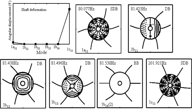
a) AMM
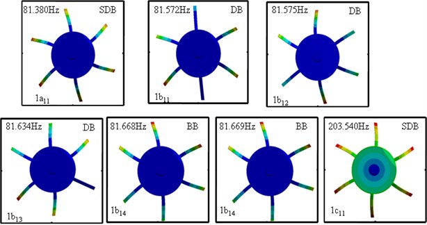
b) FEM
Fig. 6Frequency variation due to disks in a five-blades with spring
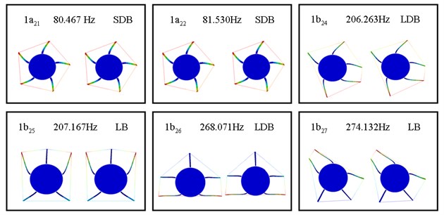
Figs. 8 to 11 and Tables 5 to 6 demonstrate the mode shapes of two flexible-disc and five-blade case by AMM and ANSYS. Because the phenomena of three discs are similar to that of two discs, only more modes could describe phenomena in the three-disc system. Here we only used the two disks rotor in this case. From these two tables and four figures, the authors observe some results. Firstly, let us see Table 6. we could find that 1 to 1 modes used AMM that have repeat modes, but used ANSYS has no repeat modes. So, we can say that ANSYS could not calculate repeated frequencies. But these frequencies are close. Secondly, the errors of using ANSYS are less than 1 % as shown in Tables 5 and 6. Here, the rotor system is the blades packeted by lacing wire. Thirdly, the AMM is focused on disk deformation, the ANSYS is focused on whole system deformation degree as shown in Fig. 5. But, how to convince the reader to believe that these results are correct, let us see the 1, 1and 1modes in the Fig. 10, we could find that the lacing wire could not affect the coupling, which is really called DB and BB modes. On the other hand, we observed that the 1to1 modes are affected by lacing wire, so we called these modes LDB or LB modes. After comparing these phenomena, we could say that the results are right in this paper.
Fig. 7Frequency variation due to disk with springs in a three disc and five-blades rotor
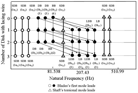
Fig. 8The first nine modes of a five-blades and two-disc by first disk spring rotor system
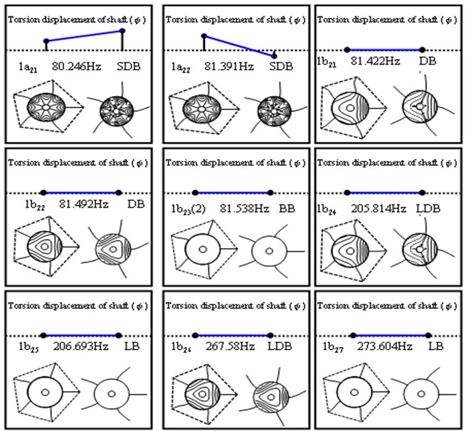
Fig. 9The first six modes of a five-blades and two-disc by spring rotor system
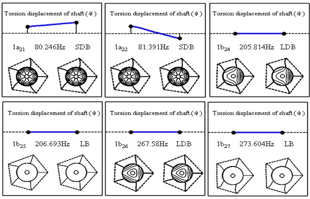
Fig. 10The first nine modes of a five-blades and two-disc with first disk spring rotor by ANSYS
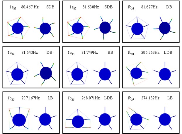
Fig. 11The first six modes of a five-blades and two-disc with spring rotor by ANSYS
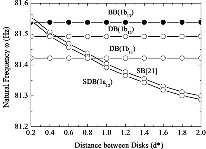
In the Fig. 12, the authors explored how the frequencies change with distance of disc for a two flexible disks and five-blade system in which 1st disk is with lacing wires. From ref. [21], the authors knew the shaft-blade (SB) modes that the frequencies decrease with increase of the disc distance. In order to compare conveniently, we drew this phenomenon in this case again. From the Fig. 12(a), we found two results. First, the frequencies of SDB (1) modes are lower than SB modes. Second, it is seemed that the frequencies of SB and SDB modes have 1 % decrease from 0.2 to 2.0 with normalize distance of disks. In the Fig. 12(b), we see that the lacing wire did not affect the DB and BB modes firstly. Next, the frequencies of SDB (1) modes decrease from higher than BB (1) modes to lower than DB (1b21) modes. The frequencies of 1 mode have 0.1 % decrease from 0.2 to 2.0 with normalize distance of disks.
Table 5The first six modes of natural frequencies (Hz) of a two-flexible disc and five-blades with 1st spring by two methods
Mode | AMM | FEM (ANSYS) | Error (%) |
1 (SDB) | 80.236 | 80.467 | 0.288 |
1 (SDB) | 81.391 | 81.530 | 0.171 |
1 (DB) | 81.422 | 81.627 | 0.252 |
1(DB) | 81.492 | 81.643 | 0.185 |
1 (BB) | 81.538 | 81.749 | 0.259 |
1 (BB) | 81.538 | 81.755 | 0.266 |
1 (LDB) | 205.814 | 206.263 | 0.218 |
1 (LB) | 206.693 | 207.167 | 0.229 |
1 (LDB) | 267.578 | 268.071 | 0.184 |
1 (LB) | 273.604 | 274.132 | 0.193 |
1 (SDB) | 156.753 | 157.87 | 0.955 |
1 (SDB) | 363.394 | 364.81 | 0.389 |
Table 6The first six modes of natural frequencies (Hz) of a two flexible disc and five-blades with spring by two methods
Mode | AMM | FEM (ANSYS) | Error (%) |
1 (SDB) | 80.236 | 80.467 | 0.288 |
1 (SDB) | 81.391 | 81.530 | 0.171 |
1 (LDB) | 205.814 | 206.263 | 0.218 |
1 (LDB) | 205.814 | 206.558 | 0.360 |
1 (LB) | 206.693 | 207.167 | 0.229 |
1 (LB) | 206.693 | 207.555 | 0.417 |
1 (LDB) | 267.578 | 268.071 | 0.184 |
1 (LDB) | 267.578 | 268.228 | 0.243 |
1 (LB) | 273.604 | 274.132 | 0.193 |
1 (LB) | 273.604 | 274.838 | 0.451 |
1 (SDB) | 156.753 | 157.87 | 0.955 |
1 (SDB) | 363.394 | 364.81 | 0.389 |
Fig. 13 shows how the spring stiffness affects the changes of natural frequencies for a flexible-disk and five-blade rotor. In this figure, we found that the frequencies of SDB, DB and BB modes did not change with the increase of spring constant. Because of the figure’s scale, the frequencies of the first five modes are too close to be observed, and we could not clearly distinguish these modes, but we could be back to see the Fig. 12 to understand these modes relations. When , the LB and LDB modes could not cause any significant change, because the spring is too soft. In the 0.01-1000 range, the spring is playing significant effect and the frequencies bifurcate clearly. When , the spring could be seemed as rigid constraint, and the frequencies merge again. The frequencies of LDB modes are lower than LB modes, although their trend is similar to each other. Because of this, the phenomenon in this figure became complicate, which proves that the disk could affect the system frequency.
Fig. 12The 1st modes frequency changes with distance of disks for a five-blade and two-disc rotor by 1st disk lacing wire
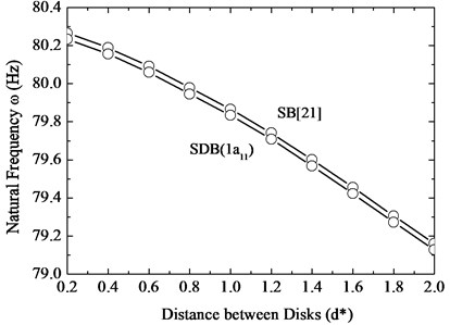
a)
b)
Fig. 13Changes of natural frequencies with spring constant in a two-disks by 1st disk spring rotor case
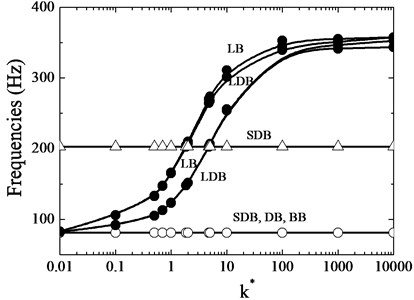
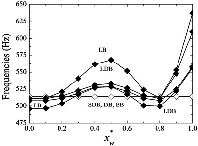
Fig. 14The 1st and 2nd mode frequency changes with spring location in a two-disks by 1st disk spring rotor case
a)
b)
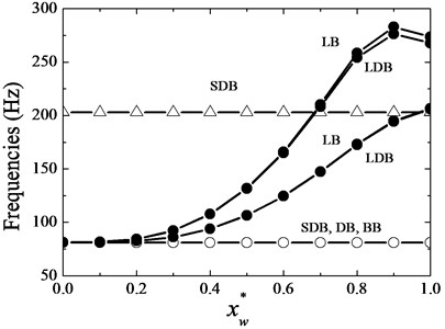
Fig. 14 shows the frequency changes with spring connection location. We found that the frequencies of SDB, DB and BB modes have no variations wherever the spring location is. As expected, when the spring connection is near outer edge, there are more influences than near inner edge, which appeared in the 1st LB and LDB modes. When the spring is close to nodes in the 2nd LB and LDB modes, it becomes ineffective. As same as in Fig. 13, the frequencies of LDB modes are lower than LB modes, although their trend is similar to each other. Because of this, the phenomenon in this figure became complicate, which proves that the disk could affect the system frequency.
5. Conclusions
The authors explored the shaft-torsion disk-transverse and blade-bending coupling vibrations phenomenon of a flexible-disk rotor system. The blades subsystem was grouped with spring. We mainly used the assumed mode method, minor used the finite element method to analyze the system, and compared their different results. The researches start with the modes change resulting from a flexible disk rotor. The coupling modes could be displayed in three group’s types, the shaft-disk-blade (SDB), disk-blade (DB) and blade-blade (BB). When the lacing wires joint the coupling, the new modes: lacing wires-blade (LB) modes and lacing wire-disk-blade mode (LDB) are defined.
After comparing the results of AMM with the ones of FEM (including using ANSYS, Nastarn and Hyperworks), this paper could confirm that the author’s previous researches are right. And, the results that using ANSYS is better than using Nastarn and Hyperworks. Because the errors are less than 1 % by ANSYS, but the errors of using Nastarn and Hyperworks are more than 2 %. Lastly, numerical calculation results also showed three phenomena that the lacing wires constant, lacing wire location and the disk with flexible would affect the natural frequencies.
References
-
Sino R., Baranger T. N., Chatelet E., Jacquet G. Dynamic analysis of a rotating composite shaft. Composites Science and Technology, Vol. 68, 2008, p. 337-345.
-
Turhan O., Bulut G. Linearly coupled shaft-torsion and blade- bending vibrations in multi-stage rotor-blade systems. Journal of Sound and Vibration, Vol. 296, 2006, p. 292-318.
-
Villa C., Sinou J. J., Thouverez F. Stability and vibration analysis of a complex flexible rotor bearing system. Communications in Nonlinear Science and Numerical Simulation, Vol. 13, 2008, p. 804-821.
-
Chiu Y. J., Huang S. C. The influence on coupling vibration of a rotor system due to a mistuned blade length. International Journal of Mechanical Sciences, Vol. 49, Issue 4, 2007, p. 522-532.
-
Chiu Y. J., Huang S. C. The influence of a cracked blade on rotor’s free vibration. ASME, Journal of Vibration and Acoustics, Vol. 130, Issues 5-2008, 54502, p. 1-8.
-
Chiu Y. J., Huang S. C. The influence of a mistuned blade’s staggle angle on the vibration and stability of a shaft-disk-blade assembly. Shock and Vibration, Vol. 15, Issue 1, 2008, p. 3-17.
-
Yim K. B., Ryu B. J. Effect of load torque on the stability of overhung rotors. Journal of Mechanical Science and Technology, Vol. 25, Issue 3, 2011, p. 589-595.
-
Zolkiewski S. Damped vibrations problem of beams fixed on the rotational disk. International Journal of Bifurcation and Chaos, Vol. 21, Issue 10, 2011, p. 3033-3041.
-
Bashmal S., Bhat R., Rakheja S. In-plane free vibration analysis of an annular disk with point elastic support. Shock and Vibration, Vol. 18, 2011, p. 627-40.
-
Sinou J. J., Faverjon B. The vibration signature of chordal cracks in a rotor system including uncertainties. Journal of Sound and Vibration, Vol. 331, 2012, p. 138-154.
-
Chouksey M., Dutt J. K., Modak S. V. Modal analysis of rotor-shaft system under the influence of rotor-shaft material damping and fluid film forces. Mechanism and Machine Theory, Vol. 48, 2012, p. 81-93.
-
Collins K. B., Sankar L. N., Mavris D. N. Application of low- and high-fidelity simulation tools to helicopter rotor blade optimization. Journal of the American Helicopter Society, Vol. 58, Issue 2013, 42003, p. 1-10.
-
Avramov K. V., Filipkovskii S. V. Nonlinear free vibrations of multi-disk rotors on ball bearings. Strength of Materials, Vol. 45, 2013, p. 316-323.
-
Kwon S. M., Yoo H. H. Vibration localization of a mistuned rotating multi-packet blade system undergoing external cyclic harmonic force. Journal of Mechanical Science and Technology, Vol. 25, Issue 11, 2011, p. 2769-2774.
-
Lee I., Shin S. S., Kim Y. R. Mistuned bladed disk forced vibration analysis based on standing wave formulation. Aerospace Science and Technology, 2011, p. 1-8.
-
Zinkovskii A. P., Kruglii Y. D. Effect of identity violations of contact interaction between shrouds on the static and dynamic stress state characteristics of blade rings. Strength of Materials, Vol. 44, Issue 2, 2012, p. 1-10.
-
Pust L., Pesek L. Vibration of circular bladed disk with imperfections. International Journal of Bifurcation and Chaos, Vol. 21, Issue 10, 2011, p. 2893-2844.
-
Luo R. Free transverse vibration of rotating blades in a bladed disk assembly. Acta Mechanical, Vol. 223, 2012, p. 1385-1396.
-
Vantadori S., Carpinteri A., Scorza D. Simplified analysis of fracture behavior of a Francis hydraulic turbine runner blade. Fatigue and Fracture of Engineering Materials and Structures, Vol. 36, 2013, p. 679-688.
-
Chiu Y. J., Chen Yang D. Z. C. H. The influence on coupling vibration of a rotor system with grouped blades due to a mistuned lacing wire. Applied Mechanics and Materials, Vols. 101-102, 2012, p. 1119-1125.
-
Chiu Y. J., Yang C. H. The coupled vibration in a rotating multi-disk rotor system with grouped blades. Journal of Mechanical Science and Technology, Vol. 28, Issue 5, 2014, p. 1653-1662.
-
Chiu Y. J., Huang S. C. Shaft-torsion and blade-bending coupling vibrations in a rotor system with grouped blades. Journal of System Design and Dynamics, Vol. 1, Issue 4, 2007, p. 748-759.
Cited by
About this article

This work was supported by the Fujian Nature Foundation, No. 2016J01039; the Qiantang River Talent Foundation, No. 2013R10075, the Zhejiang Nature Foundation, No. Y14A020001. Fujian Science and Technology Flatform Project, No. 2016H2003.
