Abstract
To promote the application of self-excited oscillation pulsed water jet in various fields, various characteristics of self-excited oscillation pulsed water jet were studied experimentally. A test system of self-excited oscillation pulsed water jet characteristics was designed, and it is composed of pulsed jet producer devices, particle image velocity (PIV) measuring system, pressure pulse test device and the confining pressure cavity suitable for a PIV test. The characteristics of flow field, pressure oscillation, pulsed cavitation and acoustic shock of pulsed jet were researched. The results showed that the axis velocity vector at nozzle outlet changes periodically, and gradually becomes smaller away from the nozzle. The peak pressure of self-excited oscillation pulsed water jet is 2.5 times higher than the common continuous jet. The wave crest and the wave trough of pulsed jet are not completely symmetric. As the pump pressure increases, the length of bubble cloud increases, and it first increases and then decreases with confining pressure increasing. The vibration acceleration of sonic boom increases and then decreases as pump pressure increases, and decreases steadily with confining pressure increasing.
1. Introduction
The high-velocity jet flow produced by supercharging equipments and nozzles, with water as its working medium, has enormous level density. Pulsed water jet exerts the impact effect on a target in the form of pulse with the characteristics of producing ultrashort pressure peak that continuously affects the target with the passage of time. As a result, the impact force on the target surface by pulsed jet has far surpassed the stagnation pressure of common continuous jet, rapidly expanding the crack fissure and, consequently, gaining a remarkable improvement on cutting and cracking capabilities of water jet.
Pulsed water jet could be generally categorized as blocking-up, squeezing impacting and excited oscillation [1-3]. Among them, the blocking-up pulsed water jet refers to the pulsed water jet produced by interruptedly cutting off the jet flow outside the nozzle using mechanical devices. Nebeker and Rodriguez [4] developed mechanical choking devices and studied the pulsed water jet from a modulating traffic of mechanical cycle that entails a complex mechanical modulating system, but its enormous power waste limited its use to particular occasions. Another flexible pipeline system generating pulsed water jet was developed by Wylie [5], while difficulties existed in its realization because of its rigorous conditions for engendering oscillating impulse. Squeezing impacting water cannon type represents the development of an ultra-high pressure pulsed water jet, illustrated by a pulse water cannon developed by Bunns at the Waterloo University and a 600 MPa energy-gathering water cannon from the Jiangsu Coal Institute, China [6]. Despite the powerful rock-breaking capability resulting from the maximum velocity of 2500 m/s of pulsed water jet generated by the water cannon, its application has been severely constrained by its complicated equipment structures, operational difficulties and short life span. The self-excited oscillation pulsed abrasive water jet is a new pulsed water jet that has become a new foreland subject focused by scholars around the world in recent years.
Self-excited oscillation pulsed jet was firstly put forward by Conn and Johnson [7]. Rockwell and Kinsely [8] discovered that, when visualizing the flow field of the self-excited oscillation pulsed jet, the ordered spiral will be engendered around the collision wall. The feedback effect of collision wall is vividly demonstrated by the periodical change in the fluid impedance when spiral, created by the interaction between jet and collision, reaches collision wall. Without a collision wall, the flow fluid will take a messy and irregular order. That is to say, the presence of a collision wall makes the oscillation in the collision area to move towards the sensitive shear layer separation area, which is beneficial to the formation of a coherent structure through the change of shear layer rendered by the movement. Grow [9] indicated that the amplification of oscillation caused by the instability of free shear layer is solely determined by Strouhal number. When oscillation frequency satisfies the relation, the shear layer instability will amplify the oscillation within the area. Chahine [10] studied the pulsed water jet device of the Helmholtz auto-oscillation cavity that utilizes the fluctuant characteristics of jet. When a jet goes through the Helmholtz auto-oscillation cavity, the resonance will take place in the case of consistency between the inherent frequency and jet pulse frequency, thus forming the intended pulsed jet. Based on theories of boundary layer and spiral, the theory, that jet is produced by fluid self-excited oscillation, is put forward by Liao [11]. According to this theory, researchers [12] in the Chongqing University and Southwest Petroleum University developed the oscillation pulsed nozzle used for oil drilling through their research on the self-excited oscillation phenomenon created by jet going through circular cylindrical cavity. Liao [13] and other scholars believed that the ceaseless repetition of generation, amplification and feedback of oscillation in the process, together with the pulse of air mass generated in the enclosure between shear layer separation line and cavity interior wall, was a precondition for the self-excited oscillation. The geometrical parameters and the form of collision wall are important in this process. On the other hand, a similar network model of self-excited oscillation pulsed jet device has been established by Li et al. [14] using the fluid network theory.
In short, the previous researches on self-excited oscillation pulsed jet primarily focused on the jet generation mechanism, pulse characteristics as well as nozzle structure optimization, etc. This new efficient pulsed jet has widespread applications in various fields. Up till now, encouraging results have been achieved in the application of a self-excited oscillation pulsed jet in low permeability reservoir perforation stimulation and improving the permeability of oil and gas reservoirs. In order to further apply the self-excited oscillation pulsed jet in these fields, research must be conducted on the basis of its characteristics of flow field, pressure pulse, cavitation and acoustic shock. To this end, the author independently developed a test system to research the characteristics of self-excited oscillation pulsed jet, which is composed of jet producer devices, particle image velocity (PIV) measuring system, pressure pulse test device and the confining pressure cavity suitable for a PIV test. Based on this system of PIV technology, experiments on the characteristics of self-excited oscillation pulsed jet were carried out, and the result provided a theoretical foundation for the universal application of the self-excited oscillation pulsed jet in oil and gas fields and soft coal seam with low permeability.
2. Pulsed jet producer devices
The replacement of various nozzle structures, as required in the experiment, makes the operation complicated and time-consuming. In order to simplify the operation, on the basis of a generating mechanism of self-excited oscillation pulsed jet, a pulsed jet experiment device with some spray capability and adjustable internal structure parameters of nozzle is designed by the author, as shown in Fig. 1.
A metal thread bushing, whose outer wall coordinates with the internal wall of resonance tube, is installed on the left side of the internal wall cavity of the front nozzle ; threading the coupling nut, the adjusting screw rod is successively connected with the center hole of the first end cover, lock nut and metal thread bushing; the front nozzle is installed on the center-right side of the internal wall cavity of the front nozzle, whereas the back nozzle is placed between the right side of the resonance tube and the second end cover; a resonant cavity chamber is formed by the right side of the front nozzle, the left side of back nozzle and the internal wall of resonance tube between them. Entering the oscillation cavity through the front nozzle, the fluid sprays from the back nozzle in the form of a pulsed jet modulated by the oscillation.
This experiment device can use front and back nozzles with different diameters, able to change the cavity length of the resonance cavity chamber by adjusting the screw rod through rotation.
Fig. 1Generation device map of self-excited pulsed water jet: 1 – coupling nut, 2 – adjusting screw rod, 3 – the first end cover, 4 – resonance tube, 5 – lock nut, 6 – front nozzle cage, 7 – metal thread bushing, 8, 10 – “o” seal ring, 9 – front nozzle, 11 – back nozzle, 12 – the second backup ring, 13 – the second end cover, 14 – oscillation cavity
3. Viewing test of pulsed jet flow field
Pulsed jet is a turbulent jet flow whose flow field has been researched for a long time. At the beginning, pitot tube and hot-wire anemometer were used to test the flow velocity, but this method, when testing the flow field, could disturb the target field, thus affecting the ultimate test result [15]. With the development of LAD (Laser Doppler Velocimetry) and PIV (Particle Image Velocimetry) techniques, the test of turbulent jet flow field becomes increasingly precise.
As compared with a pitot tube, hot-wire anemometer and LAD, the PIV, by overcoming the limits of single point measuring technique, is capable to measure two and three-dimensional instantaneous velocity across the entire field, with high measuring precision and ignorable disturbance on the flow field. Based on these merits, the visualization of the pulsed jet flow field has been realized in the test of flow filed of self-excited oscillation nozzle exit area using the PIV test system imported from the US.
3.1. Experiment devices and program
As shown in Fig. 2, self-excited oscillation nozzle (Fig. 3) was fixed on the independently developed four-dimensional water jet test board, and nozzle entrance pressure was controlled at 5.0 MPa. A PIV test system is used to dynamically observe a high-speed flow, and the system mainly includes a CCD camera, the light source and the processing software. The light source, formed by a laser transmitted to composite shot through laser gun and arm, is vertically cast upon nozzle exit jet. Its pictures are taken by a CCD camera and then processed and displayed by the Insight 3G software on the computer, and the data can be quantitatively analyzed by Tecplot to obtain the flow field of self-excited pulsed water jet.
As requested in the experiment, the experiment device was connected, Insight 3G software adjusted, and parameters set, from which 100 pictures of nozzle outlet flow filed were taken, as some of which were shown in Fig. 4.
Fig. 2Device connection schematic of testing system
Fig. 3Self-excited oscillation nozzle
Fig. 4Part of original flow field figure
3.2. Experiment results and analysis
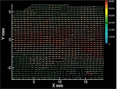
The stored pictures will be processed by software. Among the 100 original pictures of the flow field, 50 of them of superior quality were chosen to be processed by Tecplot software, which would demonstrate the self-excited oscillation nozzle exit flow filed, as shown in Fig. 5.
Fig. 5 indicates that pulsed jet velocity varies greatly. It demonstrates a periodical change along the axial velocity vector of the jet exit, like many “water cannons” shooting one by one from a machine with powerful damaging capability. On both sides there is a velocity gradient. Judging from different pulsed jets, the velocity vector decreases as it moves away from the nozzle direction, which illustrates the existence of an optimal standoff distance when pulsed water jet damages objects. Exceeding the effective standoff distance of pulsed water jet, the damaging capability will be gradually lost.
Fig. 5Velocity vector of flow field
4. Experimental study on pressure pulse characteristics
As an important reflection of pulsed jet performance, pressure pulse characteristics of jet are mostly embodied in the pressure pulse in its core area. However, a research on this aspect is limited to a test on the instantaneous average pressure at the cross section of jet, while some spot tests could be carried out on pulse pressure with no guarantee on accurate test of instantaneous pressure in the jet axial area, though. In addition, the current jet pressure pulse test device is unable to eliminate the pressure surge caused by a plunger pump, or to carry out a test on inlet pressure pulse, making it impossible to compare the inlet pressure pulse and outlet pressure pulse. Therefore, it is impossible to know the true performance of the jet producer devices.
4.1. Experiment devices and methods
To overcome the abovementioned shortcomings, the author has improved the experiment devices and methods, as shown in Fig. 6.
Fig. 6Device schematic of pressure measurement system
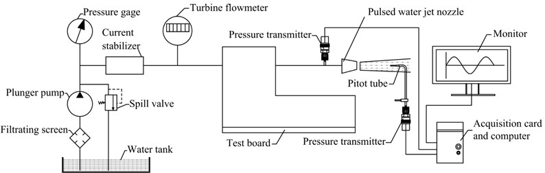
Firstly, the self-excited pulsed nozzle was installed at the test board. After eliminating the pressure undulation caused by a plunger pump through the surge tank, the plunger pump generated a high-pressure water jet upon entering the self-excited pulsed nozzle through the high pressure water pipe. Then, a pitot tube was placed in the nozzle inlet and outlet areas to achieve the pressure pulse, and a pressure transmitter was connected to the back side of pitot tube. The jet pressure pulse was then transformed into a transportable standardized current signal through the pressure transmitter, which was acquired by an acquisition card and displayed on a computer.
4.2. Experiment results and analysis
To study the pressure pulse characteristics of pulsed water jet, one pressure transmitter was installed in the front of the self-excited oscillation nozzle, the other one in its inlet. The standoff distance was set at 8 mm. The pressure signals were transferred to the pressure transmitter through pitot tube, and the collected data were processed by filtering, shown in Fig. 7.
Fig. 7Pressure comparison chart of oscillating nozzle outlet and inlet
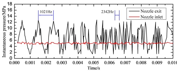
Fig. 7 shows that a large jet pressure pulse takes place at 8 mm from the self-excited oscillation nozzle outlet. The peak pressure is 2.5 times stronger than the pumping pressure, and the frequency is about 1021 Hz-2342 Hz. This illustrates the excellent pressure pulse characteristics of the pulsed jet produced by a self-excited oscillation nozzle. The increase in pulsed jet flowing pressure is beneficial to the improvement of jet performance, thus enhancing work efficiency. In addition, the small pressure undulation inside the pipe at the front of oscillation nozzle close to pump pressure also shows the excellent stabilizing effect of surge tank that is capable of eliminating the pressure undulation caused by the plunger pump, through which a more real jet pressure pulse characteristic can be acquired.
As pulsed jet has the characteristics of pressure pulse, the jet will impact the objects in dynamic load rather than be continuous. This could generate extremely high instantaneous pressure that is called as the water hammer effect. The pressure can be used to break a rock by taking an advantage of rock’s internal defects as well as of the stress wave reflection on the crack surface.
5. Experimental study of characteristics of cavitation
Cavitation is defined as the process of formation, development and disappearance of steam or bubbles (cavitation) inside a liquid or on a solid-liquid boundary surface when a decrease in local pressure inside the liquid takes place [16]. During the cavitation process, the fluid medium will change its structure. The number of gram molecules constituting medium will be changed accordingly, with the exchange between gaseous phase and liquid phase in the aspect of their quality. As a matter of fact, the cavitation process is proceeding under the circumstance of imbalance, except the cases when pressure and bubble numbers are close to those in a state of balance. In the case of a cavitation water jet, the bubbles generated inside the beam of water jet form an inhomogeneous area of gaseous and liquid phases near the object plane, changing the fluid acoustics performances like velocity of sound and oscillation frequency. When studying the cavitation phenomenon of water flow, the physical implications of dimensionless cavitation number in describing the cavitation state and characteristics lie in following formula: cavitation number = power constraining cavitation / power propelling cavitation.
In order to calculate the cavitation number, the Eq. (1) is used, as shown:
where and are the pressures at the inlet and outlet of cavitation cavity, and is the saturated vapor pressure of water.
A limited experimental research on pulsed jet cavitation characteristics has been conducted so far. Photographing the generation process of cavitation jet bubble cloud by the high velocity camera, Lu [17] discovered the elements that affect the bubble cloud length and rock-breaking capability and believed that bubble cloud length is a key indicator of cavitation jet erosion capability. Based on the research carried out, the author conducted an experimental study on the change rule of bubble cloud by using the PIV test technique and to confirm the bubble cloud length. In comparison, the PIV test technique has such advantages as short time of exposure and high test precision over a high velocity camera.
5.1. Experiment devices and methods
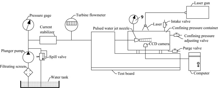
Fig. 8 is the device schematic of cavitation measurement system. As Fig. 8 shows, a self-excited oscillation nozzle is fixed at the test board. A control relief valve (including intake valve, confining pressure control valve and purge valve) controlled the nozzle inlet pump pressure of 12 MPa, and confining pressure control valve controlled the confining pressure 0.5 MPa. Its pictures were also taken and processed by the PIV system.
Fig. 8Device schematic of cavitation measurement system
5.2. Experiment results and analysis
After being transformed into a bubble cloud by the self-excited oscillation nozzle, the pure water jet will impact the surrounding medium. The internal structure change of self-excited oscillation nozzle causes the jet to spray a series of vortexes, around which the change of pressure differential will create bubbles, forming a bubble cloud that goes through the process of growth, expansion, compression and collapse.
As shown in Fig. 9, the entire process of bubble cloud generation at the self-excited oscillation nozzle inlet includes the emergence, expansion, development, compression, re-development, compression and collapse. The length of bubble cloud generated by the self-excited oscillation nozzle applicable to the perforation stimulation technology of low-permeability reservoirs reaches 18.5 mm. The number of bubbles is fairly large. As the stickiness decreases and oscillation increases, the emergence, expansion, development and compression of bubbles become more obvious, accelerating the bubble collapse, making the voice of bubble collapse stronger and harsher, thus the acoustic shock effect is made sharper. The collapse of bubble, with a greater impact force on rocks of low-permeability reservoir, will create an acoustic shock and thermal effect beneficial to reducing the stickiness of low-permeability reservoir, increasing permeability and promoting gas production.
Fig. 9Bubble cloud changes from pulsed nozzle by CCD camera
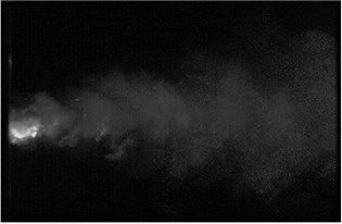
a) Emerging
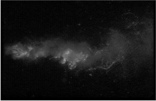
b) Expanding
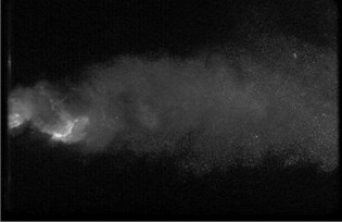
c) Developing
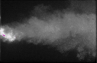
d) Developing
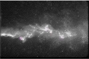
e) Developing
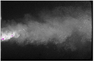
f) Collapse
6. Experimental study on acoustic shock characteristics
Cavitation acoustic shock and cavitation erosion are generally considered to be closely connected. The cavitation nucleus grows in the low-pressure zone of liquid [18]. When the nucleus radius is greater than the critical radius, the instability will incur cavitation, and the cavitation bubble moving towards the positive pressure area will rapidly collapse [19]. When the bubbles collapse, as discovered by Barber et al. [20], high temperature amounting to 5000 K and 500 local high pressure centers of atmospheric pressure will be generated. Accompanying the generated huge pressure is a strong acoustic shock effect. In fact, the acoustic shock effect runs through the process of bubble emergence, development and collapse, particularly in the phase of collapse. Two reasons are provided. Firstly, the mechanism of bubble radiation acoustic shock effect can be basically categorized into the pulsation source (monopole), as the most effective sound radiation source. Secondly, bubbles, when closing to that of the minimum radius, generate a momentarily huge volume pulse rate, indicating a strong acoustic shock effect sound pressure of radiation despite the limited volume of single bubble collapse. Therefore, the development degree of cavitation jet bubble and the supposition governing the characteristics of the generated acoustic shock can be tested by a sensor installed to measure the cavitation jet acoustic shock effect.
6.1. Experiment devices and methods
Experimental test devices of acoustic shock and heat effect of pulsed water jet cavitation are composed of a pulsed cavitation jet producer, receiving and processing system of acoustic shock signal and heat signal and computer recording and processing system. Based on the acoustic shock test board of DASP engineering version, an acceleration sensor was used to test the acoustic shock effect of the upper surface of cavitation cavity and, a temperature sensor and data recording processing software were adopted to conduct a temperature test, as shown in Fig. 10. Experiment equipment includes a high-pressure water pump, high pressure valve body, cavitation cavity, pulsed abrasive jet producer, test probe, temperature sensor, signal receiver, intelligent signal processing analyzer and computer, etc.
Fig. 10Test schematic diagram of sonic vibration and thermal condition of cavitation water jets
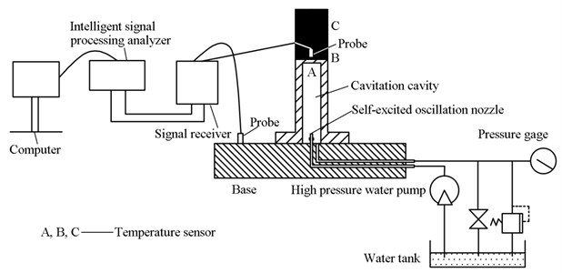
The test of acoustic shock effect is as follows. Produced by high pressure pump, a water flow, upon entering the cavitation cavity through a high-pressure pipe, forms a pulsed cavitation jet after going through the self-excited oscillation nozzle. The acoustic shock effect generated by the pulsed cavitation jet shall be acquired by the acceleration sensor on the upper surface of cavitation cavity, and the acquired signal will be analyzed and processed by a computer, from which the data and pictures are to be obtained. There are 25 combinations of pump pressure and cavitation cavity confining pressure, and the pump pressure values are 5 MPa, 10 MPa, 15 MPa, 20 MPs and 25 MPa in sequence and cavitation cavity confining pressure values are 0.1 MPa, 0.2 MPa, 0.3 MPa, 0.4 MPa and 0.5 MPa. By changing the cavitation cavity confining pressure in a proper order under the fixed pump pressure, the time domain waveform of oscillation acceleration on the top of the 25 cavitation cavities and the produced vibration spectrum were tested and recorded.
The test of heat effect is as follows. The heat generated by the pulsed cavitation jet shall be acquired by the temperature sensor on the surface A inside the cavitation cavity, surface B and point C inside a coal briquette. The acquired signals will be analyzed and processed by a computer, from which the diagram that the three points’ temperature fluctuations with time is to be acquired.
6.2. Experiment results and analysis
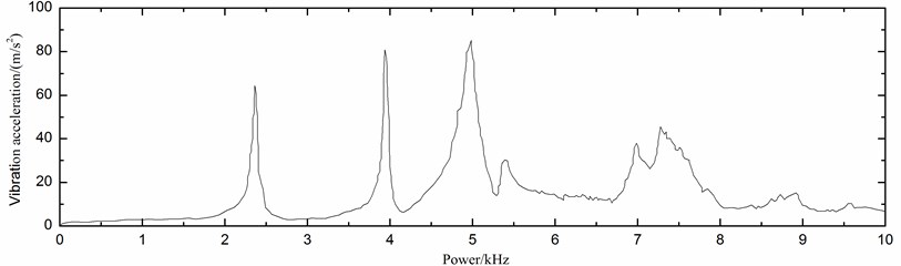
The oscillation acceleration time domain waveform of pulsed cavitation jet and the vibration frequency domain power of oscillation acceleration were tested by a vibration acceleration sensor installed on the top of cavitation cavity. Twenty-five combinations were tested by changing the pump pressure and confining pressure that were pre-designed. Fig. 11 and Fig. 12 demonstrated an oscillation acceleration time domain waveform diagram where the pump pressure is 5 MPa, and a vibration frequency domain power chart where confining pressure is 0.1 MPa. In the former diagram, the vertical axis represents the oscillation acceleration amplitude, while the horizontal axis represents a recorded time. In the latter chart, the vertical axis represents the acceleration amplitude, whereas the horizontal axis represents the frequency.
Fig. 11Vibration acceleration in different times
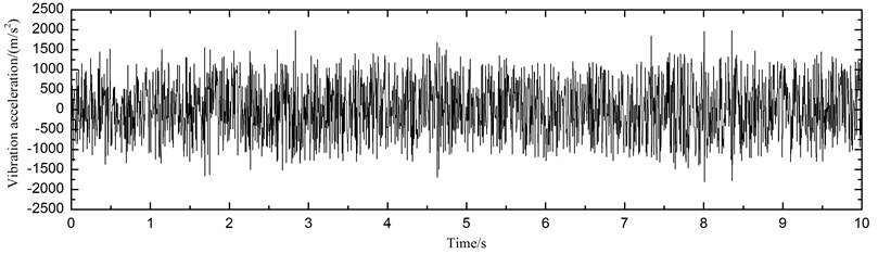
Fig. 12Vibration acceleration in different powers
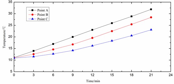
Temperature sensors were installed at the lower surface inside cavitation cavity, upper surface and Point A, B, C of a coal briquette test piece, and the pump pressure was set at 12 MPa and confining pressure – at 0.9 MPa. The variation of temperature generated by pulsed cavitation jet heat effect with time was tested, as shown in Fig. 13.
Fig. 13Variation of temperature with time
Upon analyzing the 25 tested oscillation acceleration time domain waveform diagrams, vibration frequency power charts and 3 diagrams of variation of temperature with time, the following points can be concluded.
1) The absolute value of oscillation acceleration of acoustic shock effect produced by pulsed water jet cavitation characteristics lies between 0 and 6000 m/s2. The oscillation acceleration firstly increases and then decreases when the pump pressure increases from 5 MPa to 25 MPa, and is particularly strong between 15 MPa and 20 MPa. As the confining pressure increases, the oscillation acceleration will be reduced.
2) An analysis of the frequency of acoustic shock effect produced by pulsed water jet cavitation characteristics shows a wide frequency band of acoustic shock effect oscillation at the collapse of bubble. Its impact prevails between 3000 Hz and 11000 Hz. Bubbles with different diameters correspond to different oscillation frequencies when taking effect. Bubbles with a larger diameter produce lower acoustic shock effect frequency at the time of collapse, as compared with the higher acoustic shock effect frequency generated by those with smaller diameters, which explains the big difference in the size of cavitation bubbles in pulsed water jet cavitation characteristics. The peak value of oscillation frequency that takes place between 6400 Hz and 7600 Hz has further illustrated the higher degree of concentration of bubbles within this collapse radius. The more concentrated the oscillation frequency is, the more remarkable its seepage impact on gas in low-permeability gas reservoir becomes. The acoustic shock effect produced by pulsed water jet cavitation characteristics is mainly the high frequency behavior. When the cavitation number is low, the small confining pressure as well as the large room for bubble growth makes the bubbles with large size prevail regardless of the large number. Therefore, the frequency of acoustic shock effect produced by pulsed water jet cavitation characteristics takes an inverse ratio with the bubble size. This is when the acoustic shock effect oscillation frequency is pretty low and only a few bubbles of small size at collapse engender a high frequency acoustic shock effect.
3) High pressure generates a heat effect after being turned into a pulsed cavitation water jet by a self-excited oscillation nozzle, primarily because of the large number of oscillation vortexes created by a high-pressure jet going through the self-excited oscillation nozzle. Formed by the pressure differential from vortex, the bubbles will rapidly collapse when they move to the positive pressure area, during which a high temperature will be generated. On the other hand, the bubble collapse will bring about a strong acoustic shock effect around the local high pressure area. As the stickiness of materials will absorb some sound energy because of the created internal friction between material points, when sound wave threads materials, the absorbed sound energy will be transformed into heat energy that raises the local temperature of the materials.
7. Conclusions
1) The viewing experiment on the flow field indicates that the self-excited pulsed jet velocity vector changes periodically along the jet axis, but the distribution is imbalanced in the vertical direction with the maximum velocity in the middle and velocity gradient on both sides.
2) When it comes to independently developed experiment devices for studying pressure pulse characteristics, the experiment shows that the peak value pressure of a pulsed jet is 2.5 times stronger than the pipe inlet pressure; the peak value pressure of a pulsed jet is 2.5 times stronger than the common continuous jet pressure, and the crest and trough of wave are not completely symmetrical.
3) The development process of a bubble cloud generated by the pulsed jet goes through emergence, expansion, development, compression, re-development, compression and collapse. When the fixed confining pressure is 0.5 MPa, the length of a bubble cloud grows with the increase of a pump pressure. When the pump pressure is below 8 MPa, the growth is relatively slow and begins to accelerate again after that. The phase between 13-16 MPa is another period when the growth slows. When the fixed pump pressure is 12 MPa, with the increase of confining pressure, the length of bubble cloud first increases but then decreases until it reaches the maximum value of 0.9 MPa.
4) In terms of experiment devices for acoustic shock effect of pressure pulsed cavitation jet, the experiment indicates the absolute value of oscillation acceleration of acoustic shock effect produced by pulsed cavitation jet lies between 0 and 6000 m/s2. The oscillation acceleration will firstly increase and then decrease when pump pressure increases from 5 MPa to 25 MPa, and is particularly strong between 15 MPa and 20 MPa. As the confining pressure increases, the oscillation acceleration will be reduced.
References
-
Dehkhoda S., Hood M., Alehossein H., Buttsworth D. Analytical and experimental study of pressure dynamics in a pulsed water jet device. Flow, Turbulence and Combustion, Vol. 89, 2012, p. 97-119.
-
Hasan M. A. Z., Hussain A. K. The self-excited axisymmetric jet. Journal of Fluid Mechanics, Vol. 115, 1982, p. 59-89.
-
Liu X. H., Liu S. Y., Cui X. X., Tang P. Interference model of conical pick in cutting process. Journal of Vibroengineering, Vol. 16, 2014, p. 103-115.
-
Thimons E. D., Johnson B. V., Kissel F. N. Water-jet-assist for rock cutting. E&MJ – Engineering and Mining Journal, Vol. 187, 1986, p. 40-42.
-
Choutapalli I., Krothapalli A., Lourenco L. Turbulent pulsed jet. Journal of Visualization, Vol. 9, 2006, p. 7-7.
-
Vogt U., Stiel H., Will I., Nickles P. V., Sandner W., Wieland M., Wilhein T. Influence of laser intensity and pulse duration on the extreme ultraviolet yield from a water jet target laser plasma. Applied Physics Letters, Vol. 79, 2001, p. 2336-2338.
-
Kang Y. F., Liao Z. F., Chen D. S., Den X. G. Mechanism of self-excited oscillation pulsed jet aerator. Journal of Chongqing University, Vol. 29, 2006, p. 74-77.
-
King J. L., Doyle P., Ogle J. B. Instability in slotted wall tunnels. Journal of Fluid Mechanics, Vol. 4, 1958, p. 283-305.
-
Crow S. C., Champagn F. H. Orderly structure in jet turbulence. Journal of Fluid Mechanics, Vol. 48, 1971, p. 547-556.
-
Pereira J. C. F., Sousa J. M. M. Experimental and numerical investigation of flow oscillations in a rectangular cavity. Journal of Fluids Engineering, Vol. 117, 1995, p. 68-74.
-
Tang C. L., Liao Z. F. Theoretical analysis and experimental study a self-excited oscillation pulsed jet device. Journal of China Coal Society, Vol. 3, 1989, p. 90-100.
-
Tang C. L., Pei J., Hu D. Experimental study on dynamic characteristics of self-excited oscillation pulsed jet. Advanced Materials Research, Vol. 937, 2014, p. 624-631.
-
Liao Z. F., Tang C. L. Theory of the self-excited oscillation pulsed jet nozzle. Journal of Chongqing University, Vol. 25, 2002, p. 24-27.
-
Li X. H., Wang J. S., Lu Y. Y., Yang L., Kang H. M., Sun J. J. Experimental investigation of hard rock cutting with collimated abrasive water jets. International Journal of Rock Mechanics and Mining Sciences, Vol. 37, 2000, p. 1143-1148.
-
Pianthong K., Zakrzewski S., Behnia M., Milton B. E. Characteristics of impact driven supersonic liquid jets. Experimental Thermal and Fluid Science, Vol. 27, 2003, p. 589-598.
-
Ohl C. D., Arora M., Ikink R., Jong N., Versluis M., Delius M., Lohse D. Sonoporation from jetting cavitation bubbles. Biophysical Journal, Vol. 91, 2006, p. 4285-4295.
-
Lu Y. Y., Zhou Z., Ge Z. L., Zhang X. W., Li Q. Research on and design of a self-propelled nozzle for the tree-type drilling technique in underground coal mines. Energies, Vol. 8, 2015, p. 14260-14271.
-
Igra D., Takayama K. Numerical simulation of shock wave interaction with a water column. Shock Waves, Vol. 11, 2001, p. 219-228.
-
Philipp A., Lauterborn M. Cavitation erosion by single laser-produced bubbles. Journal of Fluid Mechanics, Vol. 361, 1998, p. 75-116.
-
Barber B. P., Putterman S. J. Observations of synchronous picosecond sonoluminescence. Nature, Vol. 352, 1991, p. 318-320.
Cited by
About this article

This study was financially supported by the National Natural Science Foundation of China (NSFC) under Grant No. 51374258 and No. 51504046, Program for Changjiang Scholars and Innovative Research Team in the University of China under Grant No. IRT13043.
