Abstract
In order to study the effect of axial spacing on behaviors of aerodynamic performance and aerodynamic noises in a contra-rotating fan, the steady/unsteady Reynolds-averaged Navier-Stokes equations are solved by the numerical method in conjunction with a SST turbulence model, and the effects of axial spacing on performance and aerodynamic characteristics are investigated. Furthermore, BEM is adopted to compute the radiation noise of the contra-rotating fan caused by unsteady pressure fluctuations. The results show that axial spacing is an important factor which can affect the aerodynamic performance of contra-rotating fan. As a whole, the effect of axial spacing on the blade loading of Rotor 2 is significantly greater than that of Rotor 1. For Rotor 2, the smaller axial spacing leads to the large secondary flow loss, and the larger axial spacing leads to the strong mixing loss. With the increase of axial spacing, the radiation noise at the characteristic frequency decreases, but showed different changing degrees. With consideration of the aerodynamic performance and aerodynamic noises of the contra-rotating fan, the optimal comprehensive performance appears at the axial spacing of 0.5 chord.
1. Introduction
Reduction of energy consumption, decrease of exhaust discharge and control of noise pollution pose significant challenges for development of turbomachinery. One promising technology is the contra-rotating fan (CRF), which not only can significantly improve performance and efficiency of axial flow fan, compressor and turbine motor, but can also simply mechanical structures. In recent years, CRFs are widely applied in fields involving mine, tunnel and ship, etc. Nevertheless, relative to regular fans, contra-rotation of two rows of rotors of a CRF may lead to more complicated aerodynamic characteristics and aerodynamic noise problems.
In CRF, the axial spacing plays a major role on the rotor interaction and consequently on the noise [1]. It is a key parameter to find a compromise between high aerodynamic and good acoustic performance for CRFs. In recent years, researches on the effect of axial spacing between the two rotors in CRF are mainly concentrated in experimental and numerical computations [2, 3]. Sharma et al. [4] experimentally examined the influence of axial spacing on CRF performance. Each fan rotor has 26 blades and the hub-tip ratio is 0.66. The observed axial spacing had a more significant influence on the contra-stage performances, and the contra-stage performance was improved under the condition of 200 % chord. Roy et al. [5] studied flow behavior and performance characteristics of a CRF, wherein the front rotor has 10 blades and rear rotor has 11 blades. They reported that the performance is improved with a smaller gap of 0.5 chord. However, the study reported by Mistry et al. [6] points out that, for the axial spacing of 0.9 chord, the high aspect ratio CRF shows optimal performance, there are 19 blades in front rotor and 17 blades in rear rotor, each with an aspect ratio of 3.
With development of computer technologies and CFD technologies, the CFD method has already possessed high accuracy and manages to provide abundant flow field information. In turbomachinery researches, the numerical simulation method has been widely applied [7-9]. Mohammadi et al. [10] performed CFD simulation of a CRF, wherein the hub-tip ratio was 0.598. Research results point out that the axial spacing of 0.5 chord is the most optimum distance. However, Mistry [11] thinks, for high aspect ratio blades, the axial spacing of 0.5 chord needs not to be an optimum value. Based on this brief review, many scholars obtained different conclusions during researches on effect of axial spacing on CRF performance because the CRF researched by them had different blade geometries, blade numbers and operating conditions. The geometry and operating conditions of CRF in previous research were different from those in the presented study, which have high air volume, low blade aspect ratio, and low rotational speed. In addition, previous paper mainly focused on the overall performance. It would therefore be meaningful to study whether these differences would affect the dependence of CRF performance and investigate more CRF properties on the axial spacing size.
People have attached more and more importance on noise pollution, while aerodynamic noise has gradually become an important factor worthy of consideration in turbomachinery design. Fan noise is classified into aerodynamic noise and mechanical vibration noise. Mechanical vibration is mainly derived from mechanical design and manufacture and has been currently solved by active control technologies. Aerodynamic noise mechanism of CRF is more complicated, aerodynamic noises are relatively high [12]. With rapid development of CFD technology, technology of Computational Aerodynamic Noises (CAA) has obtained continuous improvements as well [13, 14]. Zuo et al. [12] used CFD model and FW-H equation to study the influence of blade thickness on a blower’s blade noise, and found that the noise of a blade is mainly the aerodynamic one, wherein its vibration noise or structural noise can be negligible. Li et al. [15] adopted LES and FW-H noise model to study the effect of the deviation angle of an abnormal blade on the performance of an axial fan. Results show that the main noise sources are concentrated on the leading edge and tip of the suction surface, and aerodynamic noise is generated mainly by low-frequency sound. However, the previous work failed to involve effect of axial spacing on CRF aerodynamic noise. Hence, it is really necessary to research effect of axial spacing on CRF aerodynamic acoustic performance.
Based on the CFD and BEM method, this paper simulates the turbulent flow field and aerodynamic noises of the CRF. This paper is organized as follows. Firstly, numerical investigation of the flow field is presented in a CRF under 5 axial spacing. Then, the impact of axial spacing on the aerodynamic noises is analyzed. Finally, a short list of conclusions is presented in the section of Conclusions.
2. CRF description
The research object of this paper is a FBCDZ-No.20 CRF, as shown in Fig. 1. It consists of a clockwise-rotating front rotor (Rotor 1) and an anticlockwise-rotating rear rotor (Rotor 2), with the hub ratio of 0.618. Rotor 1 and Rotor 2 had 19 and 17 blades, respectively. The design Volume flow is 64 m3/s, and the other main design parameters of the CRF are shown in Table 1.
Table 1Design parameters of the counter rotating axial fan
Design parameter | Rotor 1 | Rotor 2 |
Design speed (rpm) | –980 | 980 |
Outer diameter (mm) | 2000 | 2000 |
Blade number | 19 | 17 |
Chord(tip/mid/hub) (mm) | 195.1/210.1/223.5 | 194.8/209.7/222.6 |
Design mass flow (kg/s) | 80 | 80 |
Tip clearance (mm) | 5 | 5 |
In general, axial spacing refers to the axial distance between annular edges of two adjacent blades at the average radius position. The paper researched the CRF with five types of axial spacing. The five axial spacing cases considered include 0.3, 0.5, 0.7, 0.9 and 1.1 hub chord lengths of Rotor 1, respectively.
Fig. 1View of CRF and geometric model of blades
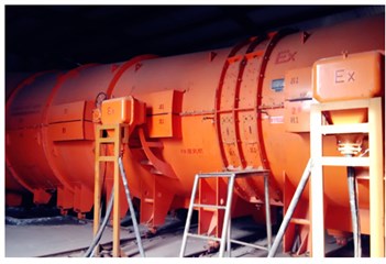
a) Contra-rotating fan
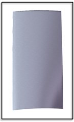
b) Front blade
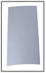
c) Rear blade
3. Computation of aerodynamic performance and flow field
3.1. Numerical method of flow field
Single-passage simulations were conducted through solution of steady three-dimensional compressible Reynolds-averaged Navier-Stokes equations. A commercial solver package of ANSYS CFX was utilized for the current work. The flow solver is a coupled pressure-based solver. It employs a fully implicit solution strategy. The steady method used a mixing plane type method called as a “Stage Interface”. The unsteady computations apply the Transient Rotor-Stator approach. The turbulence model of Shear Stress Transport model is applied, and referred to as SST model which is combined with advantages of - turbulence model in terms of simulating the near-wall boundary layer and characteristics of - turbulence model concerning small dependence towards far-field boundary conditions [16], and thus it has greater prediction accuracy and reliability.
The material used Air ideal gas. The ideal gas model used ideal gas law to calculate the local density variation in the fluid. The compressible form of the gas law is: , wherein is the absolute pressure, is the universal gas constant, is the molecular weight, and is the local temperature. Total pressure, total temperature, and flow angles were given uniformly at the inlet boundary. Averaged static pressure was adopted on the outlet boundary, while radial equilibrium static pressure boundary conditions were specified at the outlet for low mass flow rate working conditions. No-slip and adiabatic conditions are applied to all wall surfaces.
The computational mesh is generated by AUTOGRID5 [17-20] from NUMECA software. A structured grid was used, and the computing grids are divided into domains of Rotor 1 and Rotor 2. O4H topology was chosen to model the main flow passage, and butterfly topology was adopted to model the tip clearance of rotors. The numbers of stream-wise, span-wise and pitch-wise grid nodes of both Rotor 1 and Rotor 2 are 123×85×91. The minimum grid spacing on the solid wall was 2×10⁻⁶ that giving < 2 at the walls.
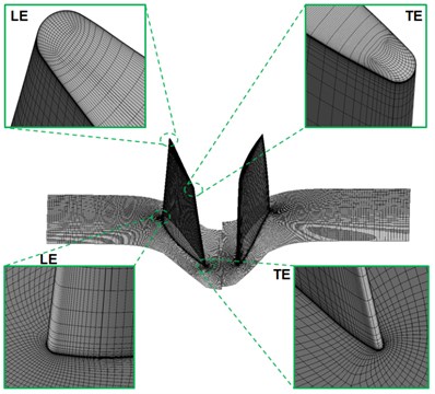
In order to verify the gird independence, 1.2×10⁶ grids are taken as the starting point, and 5 computations with different grid nodes are carried out from 1.2×10⁶, 1.8×10⁶, 2.9×10⁶, 3.4×10⁶ and 3.8×10⁶ respectively. The distribution densities of the 5 different grid nodes are similar, and are mainly used for encryption. As indicated from the computation, fan performance parameters are no longer sensitive to grid nodes when the number of nodes exceeds 2.9×10⁶. Therefore, 2.9×10⁶ grid nodes are applied for the computation in present work under consideration of computational accuracy and time. The computational grid of 0.5 chord axial spacing in the two rotors of one blade passage, including enlarged views of the grid near the tip leading edge (LE) and tailing edge (TE), is shown in Fig. 2.
Fig. 2Grid of 0.5 chord axial spacing
3.2. Results and discussions
3.2.1. Validation of simulation
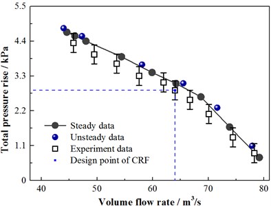
In order to verify the accuracy of numerical results, Fig. 3 shows the numerical and experimental total pressure rise performance curve at the design speed of 30 % axial spacing. The experiment had been conducted on the CRF of which the design axial spacing is 0.3 chord [21-23], as shown in Fig. 1. At the inlet of R1 and outlet of R2, two pitot probe rakes comprising eight pitot tubes (diameter of 1 mm for each tube) were employed to measure the total pressure. The probe was calibrated for non-null mode at an angular interval of 2°. The numerical results were obtained from a number of steady and unsteady simulations, the stall point was considered as the last operating point before non-convergence. The agreement of overall performance curves between the numerical results and experiments can be observed for most parts.
Fig. 3Curve of numerical and experimental total pressure rise performance
3.2.2. Aerodynamic performance
At first, the paper analyzed total pressure rise and isentropic efficiency characteristic lines of CRF. In Fig. 4(a), total pressure rise characteristic lines of CRF under 5 types of axial spacing are listed. We can find, with increase of the axial spacing, the total pressure rise of CRF increased under the same flow. Comparison between small flow working conditions and large flow working conditions shows that axial spacing could more obviously influence total pressure rise characteristics of CRF. In addition, with regard to operating margin, with increase of the axial spacing, the steady working range of CRF decreased obviously, and the stall flow shifted to the large flow direction, indicating that, for this CRF, aerodynamic steady performance of CRF is better under small axial spacing.
In Fig. 4(b), isentropic efficiency characteristic lines of CRF under 5 types of axial spacing are listed. Computation formula of isentropic efficiency is: , wherein denotes the total outlet pressure; denotes the total inlet pressure; denotes the total outlet temperature; denotes the total inlet temperature; denotes a specific heat ratio; and the superscript * denotes a stagnation state corresponding to a physical state. It is shown in the figure that under the designed flow, CRF efficiency reached the highest value under the axial spacing of 0.5 chord, and reached low values under the axial spacing of 0.3 chord and 1.1 chord. When the axial spacing increased from 0.3 chord to 0.5 chord, the efficiency increased greatly. When the axial spacing kept on increasing from 0.5 chord to 1.1 chord, the efficiency decreased gradually. In addition, under small-flow and large-flow working conditions, the CRF efficiency decreased most quickly under the axial spacing of 0.3 chord.
Fig. 4Performance map of the CRF
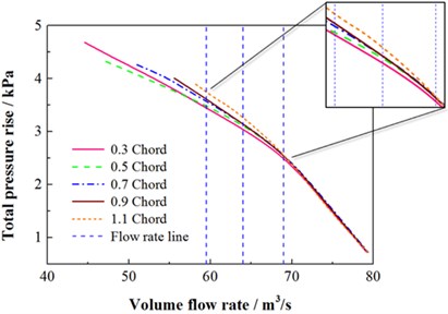
a) Total pressure rise versus volume flow rate
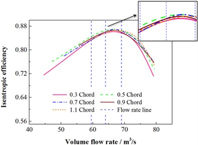
b) Isentropic efficiency versus volume flow rate
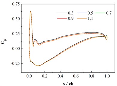
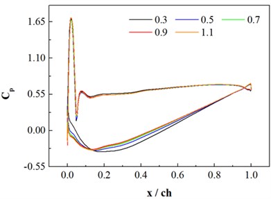
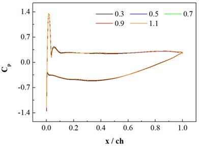
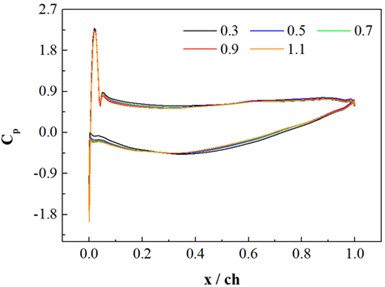
In Fig. 5, distributions of blade surface static pressure coefficients on 3 blade height cross sections of Rotor 1 and Rotor 2 are displayed. In the figure, the horizontal coordinate denotes a relative chord length, the longitudinal coordinate denotes a blade surface pressure coefficient. Their definitions are shown in Eq. (1):
where: denotes a static pressure value on the blade surface, and respectively denote the circumferential average total pressure values of different blade height at the local inlet (it is a relative total pressure value for a rotor blade) and static pressure values generated when local blades reaches different blade heights.
The area enclosed by the static pressure distribution line of the pressure surface and suction surface of fan blade reflects blade loading. Axial spacing did not obviously influence the static pressure distribution line of Rotor 1, and only exerted certain influences at the 5 % blade height cross section. At this location, in comparison with other types of spacing, the blade loading under the axial spacing of 0.3 chord were relatively higher in the front 30 % of blade chord length, so that loads of the whole chord interval increased. Axial spacing obviously influenced the static pressure distribution line of Rotor 2, which was mainly exerted on the suction face. At the 5 % blade height cross section, blade loading under the axial spacing of 0.3 chord differed obviously from other types of clearance. The blade loading of Rotor 2 were obviously lower in the front 50 % of chord length, but the blade loading were obviously high in the rear 50 % of chord length. Hence, under 0.3 chord, the adverse pressure gradient along the flow direction on the suction face of Rotor 2 was higher in the front 50 % of chord length, so that flow separation could take place more easily on the boundary layer. On 50 % and 95 % of blade height cross sections, with the increase of axial spacing, the front 10 % blade loading of Rotor 2 increased, while the rear 90 % blade loading decreased and the total blade loading in the whole chord length interval were basically equal.
Fig. 5Rotor blade surface static pressure distribution
a) 5 % relative blade height of Rotor 1
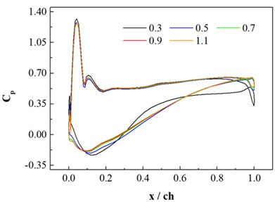
b) 5 % relative blade height of Rotor 2
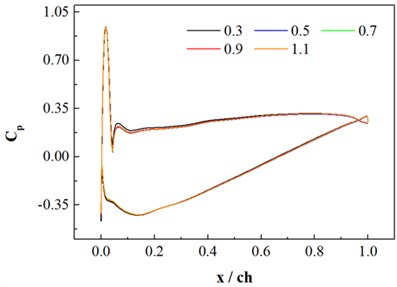
c) 50 % relative blade height of Rotor 1
d) 50 % relative blade height of Rotor 2
e) 95 % relative blade height of Rotor 1
f) 95 % relative blade height of Rotor 2
Above analysis shows that changes of axial spacing could obviously influence static pressure distribution of Rotor 2, so that flow loss characteristics of Rotor 2 were further researched. Fig. 6 displays the contour of static entropy of Rotor 2 at 50 % blade span. Three types of axial spacing including 0.3 chord, 0.5 chord and 1.1 chord possessing typical characteristics were selected. It is shown in the figure that the wake of high-energy dissipation appeared on the tail edge of Rotor 2, and energy kept on dissipating in the flow direction. Nevertheless, under different types of axial spacing, the upstream wake exerted different influences on Rotor 2. Under the 0.3 chord, a thin and long high entropy zone was located on the suction face side of the Rotor 2 in the incoming flow direction. Due to the small axial spacing, the upstream wake was not fully blended with the mainstream, so that obvious secondary flow losses took place to Rotor 2, wherein the isentropic efficiency was low for CRF at that moment. When axial spacing increased to the 0.5 chord, the high entropy zone in the incoming flow direction of Rotor 2 disappeared, the flow field was improved, and the corresponding isentropic efficiency of CRF reached the maximum value at that moment. However, when the axial spacing kept on increasing to the 1.1 chord, obvious high entropy incoming flows appeared in the flow channel of Rotor 2. Due to the large axial spacing, the upstream high entropy wakes were fully blended into the mainstream. Blending effects were strengthened, entropy production in the flow field was increased and thus large blending losses were generated. At this time, the isentropic efficiency was low for CRF. Above analysis results also coincide with the isentropic efficiency curve in Fig. 4(b).
Fig. 6Contour of static entropy of Rotor 2 under different axial spacing
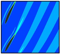
a) 0.3 Chord
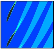
b) 0.5 Chord
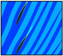
c) 1.1 Chord

4. Computation of aerodynamic noises of CRF
4.1. Numerical model of aerodynamic noises of CRF
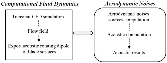
Rotating blade noise can be classified into discrete noise and broadband noise, wherein discrete noise is related with blade passing frequency and broadband noise is related with turbulence pressure pulse. In CRF, mutual interference of two-stage blade rows is obviously, discrete noise and its harmonic waves play an important role in fan noise, and sound pressure has obvious peaks under the blade passing frequency. In flow field computation of this paper, the SST turbulence model was applied. Firstly, steady flow field computation was carried out, a convergence solution of the steady computation was taken as the initial field for unsteady-state computation, and then sound pressure pulsation signals were output. In fan noise, the dipole sound source is the major noise source, so the unsteady computation results were then used in LMS Virtual.Lab to compute the dipole sound source. After that, the boundary element method was used to compute the radiation noise generated by the sound source. Specific processes are shown in Fig. 7.
Basic equation used for sound field solution is Helmholtz equation:
where, , denotes the number of sound waves, denotes an angular frequency, denotes a sound speed, denotes the frequency.
In addition, according to boundary element theories and in combination with Green formula and second Green formula, Eq. (3) can be converted into an integral equation based on the acoustic boundary, wherein denotes a Green function which can be defined as follows:
where, denotes the density of homogeneous medium in the sound field. As for random point in acoustic space, when point is located on a smooth acoustic boundary, is satisfied, when point is located in acoustic space, 1 is satisfied. According to Eq. (3), sound pressure and normal velocity of all the nodes on acoustic boundary can be solved based on boundary conditions, and then the sound pressure of random point in the acoustic space can be obtained.
Fig. 7Computational process of aerodynamic noises
In the BEM calculation, the medium is air, the density is 1.225 kg/m3, and the acoustic propagation velocity is 340 m/s. In order to obtain computation results of radiation sound field more accurately, the acoustic model adopted in this paper considered influences of a fan duct, wherein an acoustic boundary element mesh of the fan duct was input into the acoustic boundary element module, the duct model contains 10658 elements and 10788 nodes. Metal with high rigidity was set as the material of the fan duct, and influences of other types of elastic deformation were neglected. The acoustic computation model is shown in Fig. 8. The final BEM part of the CRF is shown in Fig. 8(a), and the spherical field mesh with the radius of 5000 mm is set up outside the CRF to obtain the radiation noise, the model contains 21600 elements and 21602 nodes, as shown in Fig. 8(b).
Fig. 8Acoustic computation model
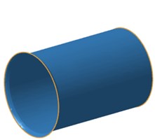
a) BEM part
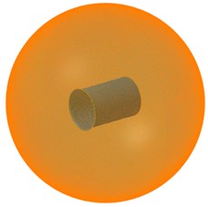
b) Spherical field point mesh
4.2. Influence of axial spacing on the sound field of the CRF
Acoustic propagation is featured by explicit directivity. Spatial points at different positions of sound field have different directions and noise spectrums. As shown in Fig. 9, in order to analyze radiation sound fields under different types of axial spacing, the rotation center of Rotor 1 was taken as the circle center; on the plane, a round monitoring curve with radius of 4000 mm was set, on the plane, a round monitoring curve with radius of 5000 mm was set, and one monitoring point was set at the interval of 10° on the curve.
Fig. 9Location of monitoring curves
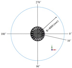
a) Monitoring curves of the plane
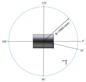
b) Monitoring curves of the plane
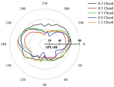
Fig. 10 displays far-field noise directivity curve diagrams of CRF under different types of axial spacing, wherein the blade passing frequency (BPF) was selected as the analytical frequency. Fig. 10(a) displays the directivity patterns of the plane. Fig. 10(b) displays the directivity patterns of the plane. It is shown in Fig. 10(a) that under different types of axial spacing and influences of the fan duct, two stages of rotors of CRF showed basically the same capability for noise radiation towards different directions. Nevertheless, with increase of the axial spacing, the average value of sound pressure level of CRF monitoring curve tended to decrease. When the axial space increased from 0.3 chord to 0.5 chord, the average value of sound pressure level decreased by 8.23 dB. When it increased from 0.5 chord to 0.7 chord, the average value of sound pressure level increased to 0.75 dB. When it increased from 0.7 chord to 0.9 chord, the average value of sound pressure level decreased by 2.39 dB. When it increased from 0.9 chord to 1.1 chord, the average value of sound pressure level decreased by 13 dB. When the axial spacing increased from 0.3 chord to 1.1 chord, the average value of sound pressure level decreased by 22.87 dB in total. Under the 5 axial spacing conditions, the CRF sound pressure levels decreased obviously under 0.5 chord and 1.1 chord.
Fig. 10Directivity patterns of the CRF under different axial spacing (BPF)
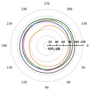
a) Directivity patterns of the plane
b) Directivity patterns of the plane
It is shown in Fig. 10(b) that the directions of 0° and 180° are respectively corresponding to inlet and outlet directions of CRF. Within certain scope of the directions of 90° and 270°, the noise radiation of CRF would be influenced by the fan duct. Hence, under different types of axial spacing, the sound pressure level reached the maximum value on the monitoring curve in the outlet direction, while the sound pressure level decreased gradually with the increase of axial spacing. In the outlet direction, under 5 types of axial spacing from 0.3 chord to 1.1chord, the reduction amounts of sound pressure level were respectively 10.22 dB, 3.67 dB, 3.43 dB and 6.47 dB. As for the CRF outlet sound pressure level under different types of axial spacing, the reduction range reached the maximum value under 0.5 chord, while the value under 1.1 chord ranked the second place.
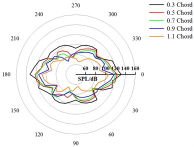
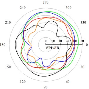
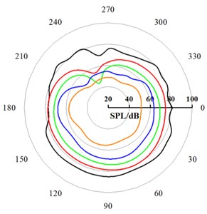
Fig. 11 and Fig. 12 display the directivity patterns of CRF under different axial spacing at 0.5 BPF and 1.5 BPF, respectively. Compared with the CRF noise radiation pointing characteristic under BPF condition, with the increase of the axial spacing at 0.5 BPF, the noise radiation directivity was significantly different, the sound pressure levels at different circumferential positions was quite different. With the increase of the axial spacing at 1.5 BPF, the directivity sound pressure level decreased as a whole. In addition, compared to 0.5 BPF and 1.5 BPF, the direction of the maximum sound pressure level at BPF was the largest, therefore, all of the noise radiation characteristics of CRF studied below were carried out at BPF.
Fig. 11Directivity patterns of the CRF under different axial spacing (0.5 BPF)
a) Directivity patterns of the plane
b) Directivity patterns of the plane
Fig. 12Directivity patterns of the CRF under different axial spacing (1.5 BPF)
a) Directivity patterns of the plane
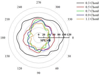
b) Directivity patterns of the plane
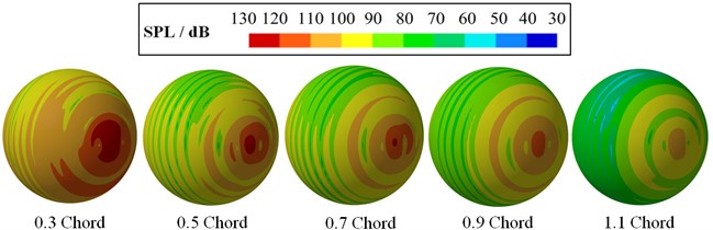
Fig. 13 displays the contour of radiation noises of the CRF under different axial spacing. It can be seen from the figure that the sound pressure level at the two-stage rotors inside the fan duct was very large, and the noise is continuously radiated to the outside, and a noticeable directivity can be observed. As the axial spacing, increased, the sound pressure level of the noise decreased as a whole. The maximum sound pressure level of the CRF with 1.1 Chord axial spacing decreased by about 30 dB in compared with the value under 0.3 Chord. Therefore, increasing the axial spacing can significantly reduce the noise level.
Fig. 13Contour of radiation noises of the CRF under different axial spacing
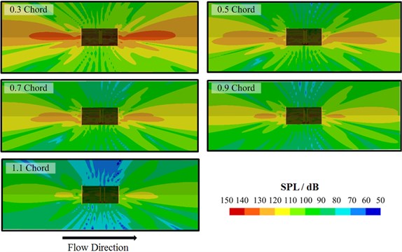
Fig. 14 displays the contour of far-field radiation noises of the CRF under different axial spacing. A field point mesh with the radius of 5000mm is established outside the CRF, as shown in Fig. 8(b). As for each spherical surface contour of CRF, the sound pressure level corresponding to the CRF outlet direction reached the maximum value, the sound pressure level corresponding to the normal direction of fan duct wall face was low, far-field noise distribution showed certain symmetry. As for CRF far-field radiation noise sound pressure levels of CRF under different types of axial spacing, the sound pressure level reached the maximum value under 0.3 chord and reached the minimum value under 1.1 chord, the sound pressure level decreased gradually under 0.5-0.9 chord, and it varied in a relatively gentle manner.
Fig. 14Contour of far-field radiation noises of the CRF under different axial spacing
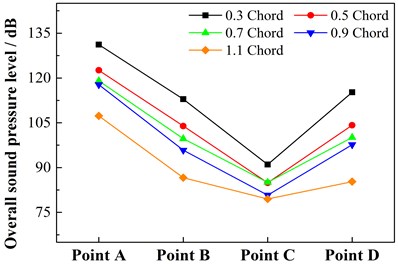
According to measurement requirements for fan outlet and fan duct radiation noise proposed in Standards of the People’s Republic of China (GB/T 2888-2008), the paper arranged 4 measurement points around CRF, as shown in Fig. 15. Point A is the measurement point for outlet radiation noise of CRF; points B, C and D are measurement points for fan cylinder radiation noise, all the distances are standard, the included angles between points B and D and the outlet axis direction is 45°. Fig. 16 displays changing curves of overall sound pressure levels at each measurement point. It is shown in the figure that under different types of axial spacing, the fan duct could obviously weaken radiation noise of the sound source, with increase of the axial spacing, the overall sound pressure level at each measurement point decreased gradually, but showed different changing degrees. Under the axial spacing of 0.3 chord, the overall sound pressure levels at each measurement point of CRF obviously reached maximum values. However, when the axial spacing increased from 0.5 chord to 0.9 chord, the overall sound pressure levels at points A, B and D were not obviously influenced. At the measurement point C, when the axial spacing increased from 0.5 chord to 1.1 chord, the overall sound pressure level did not change obviously, and the total decrease amount was 5 dB.
Fig. 15Diagram of noise receiving point
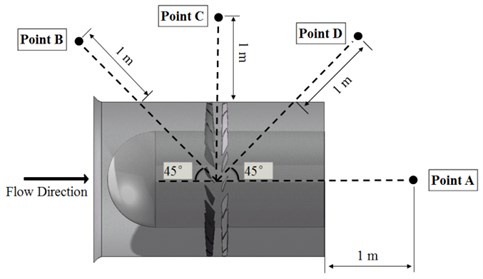
Fig. 16Overall sound pressure level in each point
During design of axial spacing, it is necessary to consider aerodynamic noise and aerodynamic performance of CRF at the same time. In conclusion, the external field radiation noise decreased, but the aerodynamic performance was also weakened when axial spacing of CRF increased. Under 1.1 chord, radiation noise reached the lowest level, but design point efficiency was low, steady working scope was minimum, and compactness of CRF was also reduced. Within the axial spacing of 0.3-0.9 chord, under the 0.5 chord, CRF had low sound pressure levels, design point efficiency reached the highest level, the steady working scope was big, and aerodynamic performance was good. Hence, based on comprehensive analysis of noise characteristics and aerodynamic performance, the optimum axial spacing for CRF is 0.5 chord.
5. Conclusions
1) The simulations show that the changes of total pressure ratio and isentropic efficiency show different trends with the increase of axial spacing. With the increase of the axial spacing, the total pressure rise of the design flow rate increases, the stable working range decreases, and the efficiency increases at first and then decreases, wherein its maximum value appears at 0.5 chord.
2) For Rotor 1, the axial spacing has little effect on the blade loading, which only has certain influence on the blade root. However, the increase of the axial spacing leads to a significant change in the blade loading of Rotor 2, which is mainly reflected on the suction surface. For Rotor 2, the flow loss is smaller at 0.5 chord axial spacing, a larger secondary flow loss occurred at 0.3 chord axial spacing, and a large mixing loss occurred at 1.1 chord axial spacing.
3) Under the design flow condition, the radiation noise of the CRF at the characteristic frequency decreases with the increase of axial spacing. Under 0.5 chord axial spacing relative to 0.3 chord axial spacing, and 1.1 chord spacing relative to 0.5 chord axial spacing, the radiation noise has a greater degree of reduction. However, considering the aerodynamic performance and aerodynamic noises of the CRF, the optimal comprehensive performance appears at the axial spacing of 0.5 chord.
References
-
Holste F., Neise W. Noise source identification in a Propfan model by means of acoustical near field measurements. Journal of Sound and Vibration, Vol. 203, Issue 4, 1997, p. 641-665.
-
Nouri H., Hussain F., Bakir F., et al. Design and experimental validation of a ducted counter-rotating axial-flow fans system. Journal of Fluids Engineering, Vol. 134, Issue 10, 2012, p. 104504.
-
Luan H. X., Chen Q. G., Weng L. Y., et al. Influence of axial spacing on a counter rotating fan aerodynamic characteristics and performance. Luid Machinery, Vol. 44, Issue 8, 2016, p. 16-21.
-
Sharma P. B., Jain Y. P., Pundhir D. S. A study of some factors affecting the performance of a contra-rotating axial compressor stage. Proceedings of the Institution of Mechanical Engineers, Part A: Journal of Power and Energy, Vol. 202, Issue 1, 1988, p. 15-21.
-
Roy B., Ravibabu K., Rao P. S., et al. Flow studies in ducted twin-rotor contra-rotating axial flow fans. ASME 1992 International Gas Turbine and Aeroengine Congress and Exposition, American Society of Mechanical Engineers, 1992.
-
Mistry C., Pradeep A. M. Effect of variation in axial spacing and rotor speed combinations on the performance of a high aspect ratio contra-rotating axial fan stage. Proceedings of the Institution of Mechanical Engineers, Part A: Journal of Power and Energy, Vol. 227, Issue 2, 2013, p. 0957650912467453.
-
Mao X. C., Liu B. A numerical study on the unsteady effect of axial spacing on the performance in a contra-rotating axial compressor. Proceedings of the Institution of Mechanical Engineers, Part C: Journal of Mechanical Engineering Science, 2016, p. 0954406216638881.
-
Shigemitsu T., Fukuda H., Fukutomi J. Wake and potential interference of contra-rotating small-sized axial fan at design flow rate. International Symposium on Transport Phenomena and Dynamics of Rotating Machinery, Hawaii, Honolulu, 2016.
-
Chang D., Tavoularis S. Effect of the axial spacing between vanes and blades on a transonic gas turbine performance and blade loading. International Journal of Turbo Jet-Engines, Vol. 30, Issue 1, 2013, p. 15-31.
-
Mohammadi A., Boroomand M. Design and internal flow analysis of a ducted contra-rotating axial flow fan. ASME 2014 International Mechanical Engineering Congress and Exposition, American Society of Mechanical Engineers, 2014, p. V001T01A075.
-
Mistry C. S., Pradeep A. M. Effect of speed ratio and axial spacing variations on the performance of a high aspect ratio, low speed contra-rotating fan. ASME Turbo Expo 2012: Turbine Technical Conference and Exposition, American Society of Mechanical Engineers, 2012, p. 63-71.
-
Zuo S. G., Qing H. U., Han H. J., et al. Influence of blade thickness on regenerative blower’s blade noise. Journal of Vibration and Shock, Vol. 33, Issue 8, 2014, p. 130-147.
-
Polacsek C., Barrier R. Numerical simulation of counter-rotating fan aeroacoustics. AIAA Paper, 2007.
-
Grasso G., Christophe J., Schram C., et al. Influence of the noise prediction model on the aeroacoustic optimization of a contra-rotating fan. Proceedings of the 20th AIAA/CEAS Aeroacoustics Conference, 2014.
-
Li C. X., Lin Q., Ding X. L., et al. Performance, aeroacoustics and feature extraction of an axial flow fan with abnormal blade angle. Energy, Vol. 103, 2016, p. 322-339.
-
Menter F. R. Two-equation eddy-viscosity turbulence models for engineering applications. AIAA Journal, Vol. 32, Issue 8, 1994, p. 1598-1605.
-
Ruan J. H., Shi Y. Monitoring and assessing fruit freshness in IOT-based e-commerce delivery using scenario analysis and interval number approaches. Information Sciences, Vol. 373, Issue 10, 2016, p. 557-570.
-
Ruan J. H., Wang X. P. Optimizing the intermodal transportation of emergency medical supplies using balanced fuzzy clustering. International Journal of Production Research, Vol. 54, Issue 14, 2016, p. 4368-4386.
-
Wei W., Fan X., Song H., et al. Imperfect information dynamic Stackelberg game based resource allocation using hidden Markov for cloud computing. IEEE Transactions on Services Computing, 2016.
-
Li J. Q., He S. Q., Ming Z. An intelligent wireless sensor networks system with multiple servers communication. International Journal of Distributed Sensor Networks, Vol. 7, 2015, p. 1-9.
-
Wong K. W., Lin Q., Chen J. Error detection in arithmetic coding with artificial markers. Computers & Mathematics with Applications, Vol. 62, Issue 1, 2011, p. 359-366.
-
Wei W., Xu Q., Wang L. GI/Geom/1 queue based on communication model for mesh networks. International Journal of Communication Systems, Vol. 27, Issue 11, 2014, p. 3013-3029.
-
Lin Q. Z., Zhu Q. L., Huang P. Z., Chen J. Y., Ming Z., Yu J. P. A novel hybrid multi-objective immune algorithm with adaptive differential evolution. Computers and Operations Research, Vol. 62, 2015, p. 95-111.
Cited by
About this article

The research work is financially supported by Natural Science Foundation of Shandong Province under No. ZR2013EEM017.
Hengxuan Luan conceived the work that acquired data, played an important role in interpreting the results. Liyuan Weng led to the submission. Yuanzhong Luan contributed materials tools and analysis tools. Yongchao Zhang performed the experiments. Peng Chen digested experimental data.
