Abstract
We have investigated possible motions of the holder on top of the polishing pad during the process of dielectric plate grinding taking into account the forces of dry friction about its axis. A mathematical model of the mechanical device has been elaborated to describe the process of dielectric wafer grinding. The model is in the form of a non-autonomous nonlinear system with a variable structure. The structure of the phase space of the dynamical system was investigated, the qualitative studies of the possible motion modes were carried out. The values of the geometrical and dynamic parameters that qualitatively and quantitatively influence the modes of the holder motion were obtained. It was found that the inclusion of dry friction forces on the axis of the free holder result in a periodic motion of the mechanism with long stops. We present the calculations of the parameters for the type 3PD-320 machine.
1. Introduction
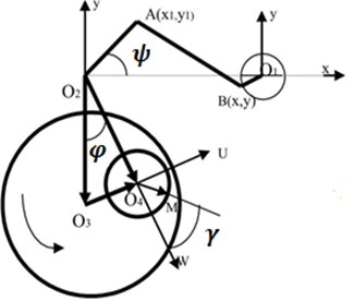
The authors in [1, 2] focus on the study of the kinematics of the process and the quality of the abrasive machining of wafer surfaces. Here, we investigate the dynamics of the mechanical grinding of dielectric wafers pasted to a free holder, whose axes are subjected to frictional forces. Schematic diagram of the mechanism is shown in Fig. 1. The wafers to be ground are pasted to the bottom of the holder (a small circle with the center at ), which is placed on the polishing pad (a large circle with its center at ). The grinding is carried out by a complex relative motion of the holder and the polishing pad. The polishing pad rotates at angular velocity . The motion of the holder’s axis (the center of ) is determined by the operation of a crank-and-rod mechanism in which the crank rotates at angular velocity . The crank through the rod AB, which is hinged at points A and B, acts on the rigid structure , so that the axis of the holder () oscillates. The rotation of the holder is determined by the effect of the friction forces between the polishing pad and the wafers pasted to the holder, and by the friction torque on the axis of the holder.
Fig. 1Schematic diagram of the grinding mechanism
1.1. Mathematical model
In the development of the mathematical model it is assumed that the relative material removal rate is proportional to the relative velocity of the piece being ground and the polishing pad (Preston’s law [3]).
Introducing the notation:
and making a series of simple transformations, we obtain the formula for calculating the velocity of the point on the holder relative to the polishing pad in the form:
where:
It follows from Preston’s law [3] that the relative rate of material removal at different points of the wafers on the holder is determined from the following Eq. (2):
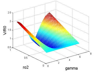
Fig. 2 shows for 22.7; 22.5; 3.5; 40; 0.4. in three-dimensional space the results of the calculations of the relative value of material removal on the wafers being ground depending on the coordinates of the wafer points: the angle , the radius , at for the mode of the holder fixed on its axis, using the MATLAB package. Let us now consider in more detail the process of grinding in the free mode of the holder. In this case, the holder’s rotation is determined by the action of the moment of the frictional forces on the holder from the pad and the friction torque on the axis of the holder.
To determine , we choose a coordinate system parallel to the system with the origin that coincides with the center of the holder. In this system, the inertial forces acting on small parts of the holder are equal to where is a part of the mass, and is the acceleration of the center of the holder. These forces do not generate torque, since the holder is disk-shaped and the wafers being ground are fixed, as a rule, symmetrically without changing the position of the center of gravity that coincides with the center of the disk. Thus we conclude that the moment is only determined by the action of the friction forces between the holder (the wafers on the holder) and the polishing pad.
A detailed study of the friction forces associated with the process of polishing is a separate large task. Therefore, to simplify, we assume that the frictional force acting on the element of the holder with the area is equal to:
The admissibility of this representation of the frictional forces is based on the similarity of the abrasive with lubricant to a high viscosity liquid. Constant is proportional to its viscosity. Then we can write Eq. (4):
Fig. 2The dependence of the relative rate of material removal S on the coordinate points of the wafer
Going to the coordinate system , , fixed relative to the holder (the axis is directed along , the axis – along , the axes , , form a right-handed space) and calculating the vector value as:
it is possible to compute the moment relative to the axis in the following way:
where is the angular speed of the holder in the coordinate system and . Here, is the radius of the holder. Thus, in the chosen coordinate system we have:
where is the moment of inertia of the holder with the wafers. Assume further that the force of friction on the axis is the Coulomb-Amontons friction and represent the moment in the following form:
Since , where is the velocity of the holder relative to its axis, and is the angular velocity of the holder drive piece, which can be considered for the above scheme approximately equal to , is the polishing pad velocity, the Eq. (6) can be rewritten as Eq. (7):
Introducing the dimensionless time , coordinate and parameters , , , Eq. (7) can be rewritten as follows Eq. (8):
The phase space of Eq. (8) is two-dimensional in the coordinates (). It has a straight line (), which divides the plane into three subspaces , and (). The motion of the image point in said subspaces is described by the Eq. (9):
Note that the motion of the image point in the subspace () takes place in time intervals corresponding to the junction of the phase trajectories coming from the subspaces , .
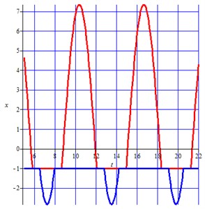
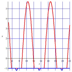
Fig. 3 (a, b) shows the phase trajectories for different parameter values 9 (Fig. 3(a)) and 7 (Fig. 3(b)), respectively, at 0.71, 3.2.
Fig. 3Phase trajectories in the plane τ, x
a)
b)
What all the parameters have in common is the presence of parameter intervals of the holder stops, which increase with a rise of the coefficient of static friction. The rotation with the stopping of the holder begins only from some values of (see Fig. 3(b)). With the increase of the parameter the intervals are shifted to the region of the shorter times, and the oscillation amplitude decreases. In the ideal case, when we can neglect friction on the axis of the holder ( 0), it follows from Eq. (6) that with the obvious relation we will obtain . This means that the angular velocity of the holder relative to its axis is . Note that for the chosen values of the parameters of the mechanism the relation holds true and hence . Assuming and that it can be approximated by the force of friction obeying the Coulomb-Amontons law, it follows from Eq. (6) that where is a small constant, which is equal to . In this case, for the steady state mode, instead of the relationship Eq. (1) we will have the following Eq. (10):
2. Conclusions
Note that according to Eq. (10):
– In the ideal case ( 0) there is no dependence of the relative velocity from the position of the point on the holder , that is, the removal of the material on the grinding disc will be uniform across the surface;
– The friction on the axis of the holder leads to a weak dependence from and thus to the non-uniform removal of the material;
– The dynamics of the mechanism is determined by the ratio of the friction torque on the axis and in the contact of the wafers with the polishing pad;
– There are three modes of the mechanism motion: free rotation, rotation with periodic stops of the holder; the holder does not rotate on its axis.
References
-
Khomich N. S., Lugovik А. Yu., Fedortsev Р. V., Korzun A. E., Kukhto P. V. Simulation of the kinematics of the process of magnetic abrasive polishing of wafers. BSTU Herald, Vol. 1, 2009, p. 33-38, (in Russian).
-
Gavrishuk Е. М., Komarovv N., Metrikin V. S., Panasenko А. G. Mathematical of wafer grinding on the machines of type 4PD-200 and 3PD-320. Bulletin of the Samara SC RАS, Vol. 13, Issue 1, 2011, p. 992-995, (in Russian).
-
Nanz G., Camille L. E. Modeling of chemical-mechanical polishing: a review. IEEE Transactions on Semiconductor Manufacturing, Vol. 8, Issue 4, 1995, p. 382-389.
About this article

Development of mathematical model is financially supported by Russian Science Foundation, project No. 16-19-10237. Investigation of numerical results was financed within the framework of the base part of State Task of the Ministry of Education and Science Project, No. 2014/134 2226.
