Abstract
The unsteady lubrication is one of the major causes for self-excited vibration in rolling. But it is difficult to build a rolling chatter model which considers the unsteady lubrication state in roll bite. Using the regression exponential function model of rolling friction coefficient, a dynamic rolling process model was built. Coupling the dynamic rolling process model with a mill stand structure model, a chatter model which considers the unsteady lubrication state at roll bite was established. Based on the proposed chatter model, the friction coefficient, rolling force and critical velocity of a rolling mill stand under different working conditions were calculated. The computed results were compared to the test results. And it proves the validity of the proposed model. With the proposed chatter model, the effects of rolling process parameters and emulsion lubricant characteristic parameters on friction coefficient and critical velocity were both analyzed and discussed. The chatter model successfully introduces the unsteady friction model into the rolling mill chatter model. It better explains the negative damping effect of the rolling chatter and reflects the rolling mill dynamic vibration characteristic.
1. Introduction
Lubrication is necessary to guarantee the proper functioning of rolling mills. It reduces energy consumption during rolling and improves the surface quality of rolled products. Lack of lubricant or overuse of lubricant can both cause chatter in rolling, which results in poor surface quality of the products and even damage of rolling equipment. Previous researches have proven that the self-excited vibration of the rolling mill derives from the roll bite. The vertical vibration, torsional vibration and horizontal vibration of mill stand couple together through the changing lubrication at roll bite [1]. The unsteady lubrication is the main cause for the self-excited vibration during rolling [2]. For the remarkable effects of friction on rolling stability, to reveal the mechanism of rolling chatter, a reasonable and accurate friction model must be used when a rolling process model is built.
The most widely used friction models are the coulomb friction model and the friction factor model. Zhao [3] and Hu [4] built regenerative chatter models of tandem rolling mills based on the coulomb friction model and friction factor model respectively. With the models, they analyzed the chatter mechanism of tandem rolling mills. The two friction models are both in simple form and can be used conveniently to calculate the rolling force and torque. However, they cannot reflect the effects of rolling process parameters on film thickness and lubrication in roll bite [5].
Due to the unique lubrication features, the friction and lubrication at roll bite can be simplified to a fluid-solid coupling problem. Tan [6, 7] proposed a dynamic friction model of the roll bite and applied it to calculate the rolling force stress. Compared to coulomb friction model and the friction factor model, the rolling stress at roll bite obtained with the dynamic friction model is more consistent with the test results, for the “pinnacle” at the neutral point disappeared. Xu [8, 9] and Dwivedy [10] used this model to study the chatter mechanism in rolling. Their research results show that there exists a jump of the rolling force stress at the neutral point and it is responsible for the onset of chatter in rolling. The dynamic friction model reflects the lubrication property at roll bite in some extent, but accuracy of the model relies on the selection of dynamic friction coefficient and it also cannot reflect the effects of rolling process parameters on friction stress.
Previous researches have shown that rolling friction is related to the rolling process parameters. Friction models which reflect the effects of rolling process parameters on rolling friction have been used in some researches. For example, the friction model related to the work roll linear velocity is used to study the stability and nonlinear characteristics of rolling mills [2, 11]. But the application of friction models which consider the effects of multiple rolling parameters is still rare.
The friction is closely related to the film thickness at roll bite. The film thickness is decided not only by the rolling process parameters, but also the characteristic parameters of emulsion lubricant used in rolling. Due to chatter in rolling, the film thickness fluctuates and the lubrication state is unsteady. The unsteady lubrication state and variation of film thickness is one of the research hotspots in recent years. Based on the fluid dynamics, the friction stress models are constructed assuming that the roll bite is in the fluid lubrication state or in the mixed lubrication state. The influences of parameters on film fluctuation were analyzed. The relationship between the film fluctuation and the rolling force fluctuation was also studied [12-14]. By coupling the unsteady friction stress model and the chatter model together, a rolling mill chatter model which takes into account both the dynamic micro lubrication characteristic and the dynamic macro vibration characteristic can be constructed. It is very helpful to reveal the mechanism of the rolling chatter. However, it is difficult to apply the unsteady friction models to the modeling of the rolling mill chatter for its complexity.
It can be concluded that the coulomb friction model, the friction factor model and the dynamic friction model cannot reflect the dynamic lubrication property of the roll bite sufficiently. The unsteady friction stress model gives a good description of the lubrication state during rolling. But it is complex and difficult to be applied into the modeling of the rolling mill chatter. A simpler friction coefficient regression model was proposed based on the data from several cold rolling product lines [15]. The regression friction model can reflect the effects of parameters on friction and lubrication in a simple form. With the regression friction model, a new rolling process model was built in this paper. Coupling it with a mill stand structure model, a rolling mill chatter model which considered the unsteady lubrication state in the roll bite was constructed finally. Based on the proposed model, the dynamic characteristic of the friction coefficient and the stability of rolling mill are both studied.
2. Mathematical models
2.1. Relationship between the film thickness and friction coefficient
If the rolling mill operates at a high speed, the relationships between the film thickness model, the friction coefficient, the dynamic rolling process model and the mill stand structure model are shown in Fig. 1.
Fig. 1Schematic illustration of the rolling mill dynamic characteristics
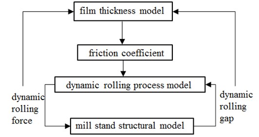
The friction coefficient is decided by the film thickness at the roll bite. The friction coefficient model has direct effects on the modeling of the rolling process. The dynamic interaction between the rolling process model and the mill stand structure model causes chatter during rolling. The chatter in rolling in return makes the rolling gap and the film thickness constantly fluctuating. By coupling the film thickness model, the friction coefficient model, the dynamic rolling process model and the mill stand structure model together, a rolling mill chatter model can be built which considers the dynamic lubrication properties at the rolling interface.
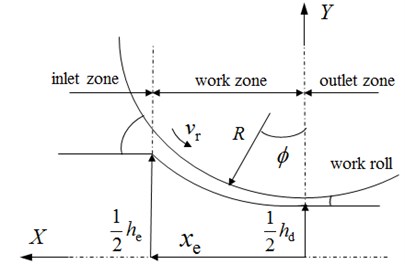
Based on the Reynolds equation, the rolling deformation zone is analyzed segmentally, as shown in Fig. 2. The film thickness models of different segments are built. Ignoring the longitudinal roughness of the work roll and the rolled strip surface, the average oil film thickness of work zone can be obtained as follows [15]:
where is the viscosity-pressure coefficient of the emulsion lubrication. is the initial dynamic viscosity at the rolling temperature of emulsion lubrication, Pa.s. is equivalent radius of the work roll, m. is the work roll linear velocity, m/s. is the entry velocity of the rolled strip, m/s. is the exit velocity of the rolled strip, m/s. is entry position of the rolled strip, m. is the deformation resistance of the rolled strip at entry position, Pa. is the entry tension stress, Pa.
Fig. 2Schematic of roll bite with lubrication
A large number of experimental studies have shown that there exist certain relationships between the film thickness and the friction coefficient. An exponential function is used to describe the relationship between the film thickness and friction coefficient. And the coefficients of the exponential function are obtained through regression analysis using the data from several cold rolling production lines. Finally, the exponential function of the friction coefficient is obtained as follows [15]:
The unit of is μm in Eq. (2).
2.2. Dynamic rolling process model
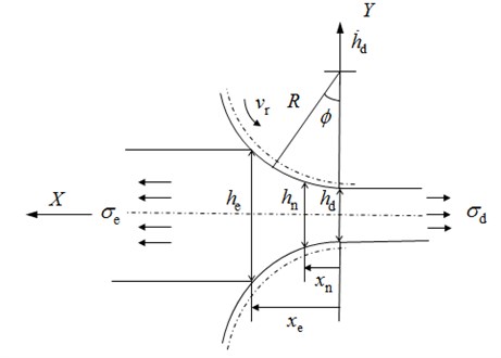
To calculate the fluctuations of the rolling force and torque, a dynamic rolling process model has to be constructed firstly. Considering the vertical vibration of the work roll, the geometrical configuration of the dynamic rolling gap is shown in Fig. 3. is the entry strip thickness. is the strip thickness at neutral point. is the exit strip thickness. is the neutral point position. is the exit position of the rolled strip. is the exit tension. is the angle between the central line of the upper and lower work roll and the line which connects the work roll center and any point on the rolling contact arc. is the initial radius of work roll. According to the control volume of the material flow with in the roll bite, the dynamic entry position , the exit position , the entry velocity of the strip and the exit velocity of the strip can be derived as follows [16]:
Fig. 3The dynamic rolling gap
The work hardening effect and the elastic flattening of the work roll are considered during the modeling process. According to the equilibrium equation in the rolling deformation zone, the rolling stress of the entry zone and the exit zone are calculated as follows [16]:
According to the force equilibrium at the neutral point, the neutral point position can be derived as follows [16]:
Different from the coulomb friction model, the friction coefficient is no longer a constant. The friction coefficient fluctuates along with the vibration of the rolling mill. By applying the first order Taylor expansion to , , , , , , , and in sequence with respect to , , , and , the rolling process model is linearized. Finally, the dynamic rolling process model is obtained as follows:
The coefficients , , and , when 1, 2, 3, 4, 5, are the partial differentiation corresponding to each variable. The derivation process of these coefficients is shown in Appendix.
2.3. Rolling mill chatter model
Considering only the vertical vibration, a four-high mill stand can be simplified to an asymmetrical spring-mass model with six degrees of freedom, as shown in Fig. 4 [17].
Fig. 4Asymmetric rolling mill stand structure model with six degree of freedoms
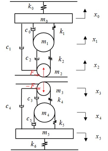
In Fig. 4, , , , , , are the equivalent mass of upper part of the mill stand, the top backup roll, the top work roll, the bottom work roll, the bottom backup roll and bottom part of the mil stand respectively. , , , , , are the vertical displacements of , , , , , respectively. is the equivalent stiffness between the upper part of the mill stand and base. is the equivalent stiffness between the top backup roll and the upper beam. is the equivalent stiffness between the top backup roll and top work roll. is the equivalent stiffness between the bottom backup roll and bottom work roll. is the equivalent stiffness between the bottom backup roll and the bottom beam and is the equivalent stiffness between the bottom part of the mill stand and base. is the equivalent damping of the hydraulic screw down system. and are equivalent damping of the upper positive and negative bending cylinders respectively. and are equivalent damping of the bottom negative and positive bending cylinders respectively. is equivalent damping between the bottom backup roll and the bottom part of the mill stand. is the dynamic rolling force fluctuation. Coupling the mill stand structural model and the dynamic model together, a chatter model is constructed as shown in Eq. (13). The vertical fluctuation of roll bite is decided by the upper and bottom work roll displacements together, namely and .
3. Validation and simulation of chatter model
3.1. Validation of chatter model
Taken the fourth stand of tandem rolling mill as example, the equivalent flattened radius of the work roll, the friction coefficient and the rolling force are calculated according to the flow chart shown in Fig. 5.
Fig. 5Calculation flow of the friction coefficient and the rolling force
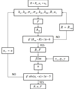
At first, the initial work roll radius and initial friction coefficient are put into the program. The equivalent flattened radius and rolling force are obtained through several rounds of convergent computation. And then with the calculated equivalent flattened radius of the work roll, the film thickness and friction coefficient are calculated. The calculated friction coefficient is compared with the value obtained in the last round. If it meets the convergence condition, the calculation stops and exports the rolling force and friction coefficient. And then the calculated coefficient is introduced into the rolling mill chatter model. With the Routh criterion, the stability of the rolling mill is analyzed and the critical velocity is obtained.
The structural parameters of the rolling mill are shown in Table 1. The initial dynamic viscosity at 70 °C is set as . The viscosity-pressure coefficient is set as 2×10⁻⁸. The rolling process parameters and the calculated results of friction coefficient, rolling force and critical velocity are shown in Table 2. As shown in Table 2, the rolling forces obtained with the proposed model are quite close to the test data. It proves that the model is enough accurate and efficient to calculate the rolling force. The errors between the critical velocities obtained using the proposed and the test data are also very small. It indicates that the chatter model is also efficient to obtain the critical velocity of the rolling mill.
Table 1Structural parameters of the rolling mill stand
Equivalent mass (103Kg) | ||||||
119 | 75 | 9.2 | 9.2 | 75 | 36.5 | |
Equivalent stiffness (1010N/m) | ||||||
6.9 | 3.0 | 6.06 | 6.06 | 4.4 | 10.1 | |
Equivalent damping (108 N.s/m) | ||||||
7.12 | 4.25 | 6.05 | 6.05 | 4.25 | 7.12 |
Table 2Comparison of the testing and calculated rolling force and critical velocity
Parameters | Working conditions | |||
1 | 2 | 3 | ||
/ 10-3m | 0.755 | 0.789 | 0.705 | |
/ 10-3m | 0.568 | 0.577 | 0.506 | |
/ 106 Pa | 156 | 180 | 185 | |
/ 106 Pa | 197 | 189 | 175 | |
/ (10-3m) | 1206 | 1206 | 1020 | |
Rolling force (103N) | Test | 8971 | 9002 | 8740 |
Ref [17] | 8965 | 9084 | 8717 | |
Ref [18] | 8983 | 9012 | 8487 | |
The proposed model | 8268 | 8751 | 7600 | |
Friction coefficient | Ref [17] | 0.04 | 0.04 | 0.04 |
Ref [18] | 0.04 | 0.04 | 0.04 | |
The proposed model | 0.0202 | 0.0283 | 0.028 | |
Critical velocity (m/s) | Test | 20.33 | 18.17 | 21.67 |
Ref [17] | 26.00 | 23.80 | 25.40 | |
Ref [18] | 21.30 | 20.60 | 20.58 | |
The proposed model | 18.90 | 18.20 | 17.70 | |
The rolling force and the critical velocity in this paper are a little smaller than the results obtained by Wang [17] and Zeng [18]. It is because that the friction coefficient in Ref [17]and Ref [18] is set as 0.04, but the friction coefficient in this paper is obtained according to the relationship between film thickness and friction coefficient. The friction coefficient in this paper is decided by the rolling process parameters and the emulsion lubricant characteristic parameters and smaller than the assumed value 0.04. The calculated results prove the validity of the proposed model in predicting the critical velocity of the rolling mill. Besides, the proposed model can reflect the effects of parameters on the friction coefficient and avoid too large critical velocity caused by the assumed inaccurate friction coefficient.
3.2. Simulation of the chatter model
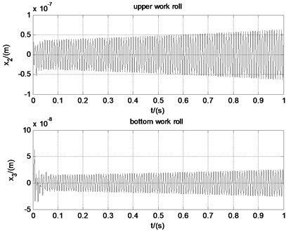
Given the initial condition that 1×10⁻⁷, 1×10⁻⁷. Simulation of the rolling mill near the critical velocity is conducted with the help of MATLAB. When the work roll, linear velocity is 18.00 m/s, the friction coefficient is 0.028 and the rolling force is 8.77×10⁶ N. Vibration of the rolling mill tends to be convergent, as shown in Fig. 6. When the velocity is 18.20 m/s, the friction coefficient is 0.0285 and the rolling force is 8.75×10⁶ N. The upper and bottom work roll oscillate periodically, as shown in Fig. 7. When the velocity is 18.40 m/s, the friction coefficient is 0.0281 and the rolling force is 8.69×10⁶ N. Vibration of the rolling mill tends to be divergent, as shown in Fig. 8. The simulation results prove that the critical velocity obtained with the chatter model is correct. And it indicates that friction coefficient and rolling force decrease with the work roll linear velocity. Besides, it can be seen from the simulation results that vibration of the upper work roll is more severe than the bottom work roll. It is because that the chatter model is asymmetric and the equivalent stiffness of the bottom part of the rolling mill is larger than that of the upper part.
Fig. 6Time domain of the rolling mill when vr= 18.00 m/s
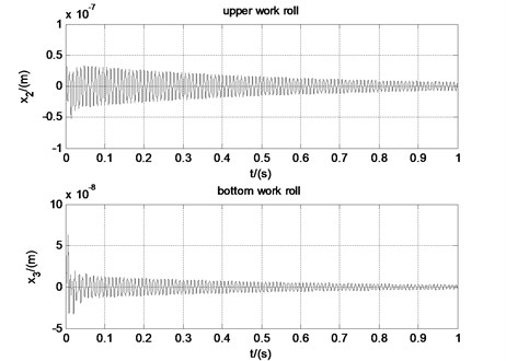
Fig. 7Time domain of the rolling mill when vr= 18.20 m/s
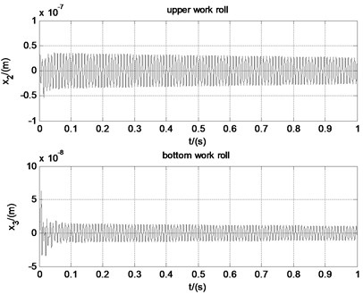
Fig. 8Time domain of the rolling mill when vr= 18.40 m/s
The fluctuations of friction coefficient under different work roll velocities are shown in Fig. 9. When the work roll, linear velocity is smaller than the critical velocity, for example 17.40 m/s, the friction coefficient fluctuation tends to be convergent. When the work roll liner velocity is 18.20 m/s, namely the critical velocity, the friction coefficient oscillates periodically, but the amplitude is very small. When the work roll, linear velocity is larger than the critical velocity, for example 19.50 m/s, the friction coefficient tends to be divergent and the amplitude increases quickly. It shows that the proposed chatter model is effective to simulate the unsteady lubrication and friction state during rolling and couple it together with the rolling mill chatter model.
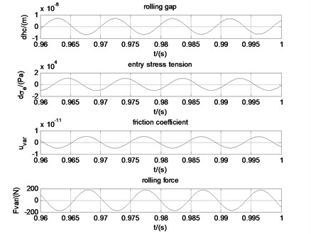
The phase relationship between the friction coefficient, rolling force, entry stress tension, and rolling gap is shown in Fig. 10. It can be seen that the phase difference between the rolling gap and the rolling force is 180°, 90° between the rolling gap and back stress tension, 90° between the rolling force and back stress tension. According to previous researches, the phase differences between the rolling gap, entry stress tension and rolling force cause the self-excited vibrations during rolling. It is concluded as negative damping effect [4]. But the previous researches do not reflect the phase of friction. According to our research, as can be seen in Fig. 10, the rolling force and the friction coefficient are substantially in phase. The variation of the rolling gap causes the vibration of the stress tension. The stress tension fluctuation causes the variation of the friction. The friction variation gives rise to the rolling force variation, which directly causes vibration of the upper and bottom work roll.
Fig. 9Fluctuations of friction coefficient under different work roll velocities
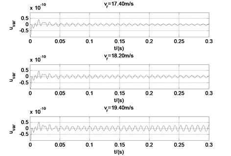
Fig. 10Phase relationships when the work roll velocity is 18.2 m/s
4. Dynamic characteristics of the rolling mill
4.1. Effects of parameters on friction coefficient
Based on the regression friction coefficient model and taken the second working condition as example, the effects of rolling process parameters and emulsion lubricant characteristic parameters on friction coefficient are analyzed. The analysis results are shown in Fig. 11. The -axis is the change percent of the parameters. The -axis is the corresponding change percent of friction coefficient. The friction coefficient increases quickly with the entry thickness of the rolled strip, and decrease quickly with the exit thickness of the rolled strip. It indicates that friction coefficient rises up with the rolling reduction. The friction coefficient increases with the entry and exit tension stress. And the entry tension stress has more great effect on the friction coefficient than the exit tension stress. The friction coefficient decreases with the deformation stress of the rolled piece, the initial work roll radius, the initial dynamic viscosity, the viscosity-pressure coefficient and the linear velocity of the work roll.
If the parameters change in certain range, the curves in Fig. 11 tend to be straight lines. The slopes of these lines can be considered as the influence factors of parameters on friction coefficient. These parameters are listed in descending order according to the influence degree on friction, namely the rolling reduction, emulsion initial dynamic viscosity, emulsion viscosity-pressure coefficient, work roll linear velocity, initial work roll radius, deformation stress of the rolled strip and tension stress between adjacent stands. It needs to be pointed out that the influence degrees of the emulsion initial dynamic viscosity, emulsion viscosity-pressure coefficient and the work roll linear velocity are almost the same. It can be seen from the above analysis that the friction coefficient changes with the rolling parameters. It is not accurate to assume that the friction coefficient is a constant when we study the dynamic characteristic of the rolling mill.
Fig. 11Effects of parameters on friction coefficient
4.2. Effects of parameters on critical velocity
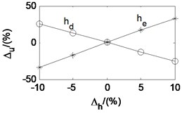
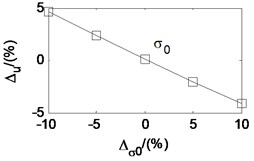
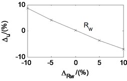
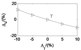
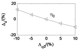
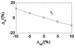
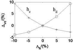
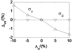
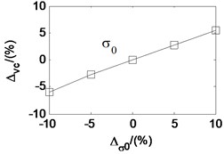
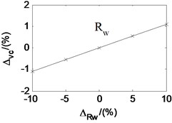
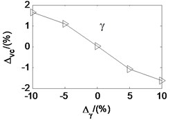
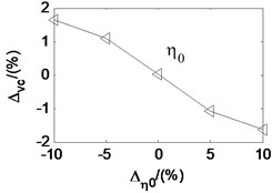
Taken the second working condition as example and based on the proposed rolling mill chatter model, under the condition that other parameters remain unchanged, the effects of each parameters on the critical velocity are also analyzed. The analysis results are shown in Fig. 12. The -axis is the change percent of the parameters. The -axis is the corresponding change percent of critical velocity. It can be seen that the critical velocity decreases quickly with the strip entry thickness, and increase quickly with the strip exit thickness. It indicates that critical velocity decreases along with the rolling reduction. The critical velocity goes down with the tension stress between adjacent stands, the emulsion initial dynamic viscosity, and the emulsion viscosity-pressure coefficient. However, it increases with the deformation stress of the rolled piece and the initial work roll radius. Analogy to the parameter effect on the friction coefficient, the parameters are listed in descending order according to the influence degree on critical velocity, namely the rolling reduction, the deformation stress of the rolled strip, the emulsion initial dynamic viscosity, the emulsion viscosity-pressure coefficient, the stress tension, and the initial work roll radius.
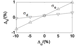
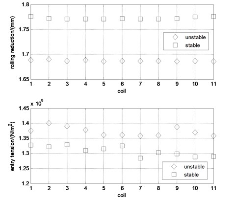
The rolling schedule is the key line in rolling technology. Once setup, no arbitrary changes are permitted in production. So, it is difficult and expensive to conduct experiments to study the effects of rolling parameters on critical velocity. But we can obtain the influence rules through the statistical test data of rolling parameters when the rolling mill vibrates. In Ref [19], the vibration signals of a rolling mill were detected many times and the rolling parameters were recorded. Through the statistical analysis of the parameters, the influence of parameters on the stability of the rolling mill can be concluded. According to the statistical result, as can been in Fig. 13, smaller the rolling reduction and larger the entry stress tension is, the more easily the rolling mill tends to vibrate. The conclusions are consistent with the simulation results in the paper.
Previous studies have shown that the critical velocity increase with the friction efficient [1]. But there is one point needed to be clarified. Wrong conclusions may be obtained if we judge the effects of parameters on critical velocity through the effects of parameters on the friction coefficient. As discussed above, the friction coefficient decreases with the exit strip thickness, deformation stress of the rolled strip and the initial work roll radius, but the critical velocity increase. The friction coefficient increases with the entry strip thickness and the stress tension, but the critical velocity decreases. It can be explained by that the rolling process parameters do not only affect the friction coefficient, but also influence the equivalent stiffness and equivalent damping of the rolling mill. If these parameters are adjusted properly, it is possible that the friction coefficient remains the same, while the critical velocity is changed. The conclusion that critical velocity increases with the friction efficient is tenable only under the condition that other rolling process parameters do not change.
According to the research results in this paper, the critical velocity decreases with increase of the emulsion dynamic viscosity and pressure-viscosity coefficient. But the research results in Ref [20] show that the critical velocity are almost unchanged with increase of the dynamic viscosity and pressure-viscosity coefficient, and it increases with the film limiting shear stress. The dynamic rolling process model in Ref [19] is constructed based on the assumption that the roll bite is in the full film lubrication state. When the friction stress exceeds the film limiting shear stress, the film breaks and the friction stress equals to the limiting shear stress. The rolling mill in Ref [20] just works under the condition that the friction stress exceeds the film limiting shear stress. So, the critical velocity kept almost unchanged when the dynamic viscosity and pressure-viscosity coefficient increased. Except for the dynamic viscosity and pressure-viscosity coefficient, the concentration of the emulsion lubricant is also an important parameter which affects the stability of the rolling mill. The study of effects of emulsion lubricant concentration on the critical velocity is most conducted through experiments.
Fig. 12Effects of parameters on critical velocity
According to the experimental results, the critical velocity decreases with the increase of emulsion concentration. By decreasing the concentration of emulsion lubricant or adding solid additives into lubricating oil, the rolling mill vibration can be controlled [1, 21]. According to the relationship between the emulsion lubricant concentration and the dynamic viscosity, greater the emulsion lubricant concentration is, larger the initial dynamic viscosity is. And so, the critical velocity decreases as the dynamic viscosity and pressure-viscosity coefficient increase. It is consistent with the simulation results in the paper.
Fig. 13The test statistics results of rolling process parameters
5. Conclusions
Using the regression friction model based on the relationship between the film thickness and friction coefficient, a new rolling chatter model was built in this paper which considers the unsteady lubrication state at roll bite. With the proposed model, the effects of parameters on friction coefficient and critical velocity are both analyzed. It reflects the dynamic behavior of the whole rolling system.
The proposed chatter model successfully couples the micro lubrication dynamic characteristics in roll bite and the macro dynamic rolling chatter characteristics together. The lubrication state vibrates in the roll bite. The phase differences between the rolling gap, the tension stress, the friction coefficient and the rolling force cause the self-excited vibration in rolling. The rolling mill stability is codetermined by the rolling process parameters and the emulsion characteristic parameters.
However, the regression friction model is proposed based on the relationship between the oil film thickness and the friction coefficient. The conclusions obtained in this paper are only applicable when the film is not fractured in the roll bite. Despite the limitations, this research gives better explanations to the mechanism of chatter in rolling and is helpful to put forward new chatter controlling methods through the optimization of rolling process parameters and the lubrication state in roll bite.
References
-
Zhou J. X. Tandem Mill Vibration Control. 1nd Ed., Metallurgical Industry Press, Beijing, 1998.
-
Chen C., Li Y. R. Influence of rolling lubrication on the self-excited vibration of rolling mill main drive system. Journal of Vibration and Shock, Vol. 34, Issue 16, 2015, p. 161-165.
-
Zhao H. Y. Regenerative Chatter in Cold Rolling. Northwestern University, 2008.
-
Hu P. H. Stability and Chatter in Rolling. Northwestern University, 1998.
-
Gao Z. Y., Zang Y., Zeng L. Q. Review of modelling and theoretical studies on chatter in the rolling mills. Journal of Mechanical Engineering, Vol. 51, Issue 16, 2015, p. 87-105.
-
Tan X. C. Friction of plasticity: application of the dynamic friction model. Proceedings of the Institution of Mechanical Engineers, Part J: Journal of Engineering Tribology, Vol. 221, Issue 2, 2007, p. 115-131.
-
Tan X. C., Yan X. T., Juster N. P., et al. Dynamic friction model and its application in flat rolling. Journal of Materials Processing Technology, Vol. 207, Issue 1, 2008, p. 222-234.
-
Xu Y., Li Q., Tong C. N., et al. Vertical vibration mechanism analysis of aluminum cold rolling mills based on the dynamic friction equation in roll gap. Journal of University of Science and Technology Beijing, Vol. 36, Issue 1, 2014, p. 104-109.
-
Xu Y., Li Q., Tong C. N., et al. Vertical vibration model for unsteady lubrication in rolls-strip interface of cold rolling mills. Advances in Mechanical Engineering, Vol. 4, 2012, p. 734510.
-
Dwivedy S. K., Dhutekar S. S., Eberhard P. Numerical Investigation of Chatter in Cold Rolling Mills. Materials with Complex Behaviour II. Springer Berlin Heidelberg, 2012, p. 213-227.
-
Zeng L. Q., Zang Y., Gao Z. Y., et al. Stability analysis of the rolling mill multiple-modal-coupling vibration under nonlinear friction. Journal of Vibroengineering, Vol. 17, Issue 6, 2015, p. 2824-2836.
-
Fu K., Zang Y., Gao Z. Y. Fluid lubrication rolling characteristics of unsteady rolling interfaces. Journal of University of Science and Technology Beijing, Vol. 35, Issue 1, 2014, p. 97-103.
-
Fu K., Zang Y., Gao Z. Y. Mixed lubrication characteristics of cold rolling process. Journal of Northeastern University (Natural Science), Vol. 35, Issue 7, 2014, p. 1005-1014.
-
Fu K., Zang Y., Gao Z. Y. Unsteady lubrication film characteristics at rolling interface. Journal of Northeastern University (Natural Science), Vol. 35, Issue 9, 2014, p. 1324-1328.
-
Design Theory of Cold Rolling Lubrication System and Mechanism Research of Mixed Lubrication System. State Key Laboratory of Rolling Technology and Rolling Automation (Northeastern University (China)), Metallurgical Industry Press, No. 0011, 2015.
-
Liu X. C., Zang Y., Gao Z. Y., et al. Time delay effect on regenerative chatter in tandem rolling mills. Shock and Vibration, Vol. 2016, 2016, p. 4025650.
-
Wang C. S., Sun M. S., Yuan X. Simulation and analysis of chatter phenomenon on cold mill rolling wide strip. Journal of University of Science and Technology Beijing, Vol. 13, Issue 1, 1994, p. 57-60.
-
Zeng L. Q., Zang Y., Gao Z. Y., et al. Study on overall coupled modeling of the rolling mill. Journal of Mechanical Engineering, Vol. 50, Issue 10, 2015, p. 58-65.
-
Mi K. F. Research on Vibration and Chatter Marks of the Wide Tandem Cold Rolling Mill. University of Science and Technology Beijing, 2012.
-
Heidari A., Forouzan M. R., Akbarzadeh S. Development of a rolling chatter model considering unsteady lubrication. ISIJ International, Vol. 54, Issue 1, 2014, p. 165-170.
-
Wei L. Q., Dai Z. F., Xiao Z., Qu Z. H. Research of vibration and strategy in high speed cold-rolling mill. Journal of Mechanical Engineering, Vol. 52, Issue 11, 2016, p. 88-94.
Cited by
About this article

The authors gratefully acknowledge the support of the National Natural Science Foundation of China No. 51175035, Ph.D. Programs Foundation of Ministry of Education of China No. 20100006110024, the Fundamental Research Funds for the Central Universities No. FRF-BR-14-006A, and Beijing Higher Education Young Elite Teacher Project No. YETP0367.
