Abstract
In the existing friction coefficient models, the influence of relatively horizontal vibration of rolled piece is always overlooked, this makes the friction coefficient model error and ultimately affects the accuracy of vibration model of rolling mill. In order to be more close to the actual situation, the vertical vibration model of strip mill is established by considering the effect of horizontal vibration of rolled piece. The approximate analytic solutions are obtained by multiple scales method. Then, bifurcation characteristics of system are analyzed by means of Singularity theory. Finally, frequency responses of system are investigated with the change of external excitation amplitudes and internal nonlinear parameters. Results show that vibration behavior of system changes with the external excitation amplitudes and frequencies, internal nonlinear parameters and coupling parameters. Moreover, the unstable frequency region of system can be obtained by amplitude-frequency curve.
1. Introduction
Plate and strip is the most popular rolling product, widely used in automobile manufacturing, shipping, aerospace and military field processing [1]. With the development of society, the size precision and surface quality of the plate and strip has been put forward higher requirements [2]. However, the vertical vibration of rolling mill has been a problem for enhancing the efficiency of cold rolling products all over the world. The vertical vibration of rolling mill will produce vibration mark in strip and roll surface, so that the quality of the products will be greatly discounted. Furthermore, the severe vibration of rolling mill even cause broken belt and equipment damage accidents, resulting in serious economic losses [3-5].
For the vertical vibration problem of strip mill in the rolling process, experts and scholars have established a variety vertical vibration models of rolling mill from different angles, and some suggests are given to restrain the vertical vibration of rolling mill. Yarita et al. presented a linear spring-dumping model to represent the interaction between roll system and upper beam of frame. He built a 4-DOF vibration model to study the vertical vibration of rolling mill [6]. Tamiya et al. considered that the mass of work roll is far more less than the backup roll, so he omitted the mass of work roll and built a 2-DOF vibration model based on the research of Yarita [7]; Soon after, Roberts et al. assumed that the rolling mill structure is equivalent along the rolling line, so he presented a single freedom vibration model of rolling mill [8]. With the development of nonlinear science, scholars begin to study the vertical vibration characteristics of rolling mill under the influence of nonlinear stiffness and nonlinear damping. Liu et al. set up a piecewise nonlinear vibration model of the hydraulic cylinder, and the vibration behavior of rolling mill with the nonlinear constraint of hydraulic cylinder were studied [9].
In recent years, with the further research on the vibration of rolling mill, some of vibration phenomena of the mill cannot be explained by simple rolling process theory. Scholars begin to study the mill vibration from coupling angles. Yun et al. formulated a 2-DOF coupling model by coupling the horizontal vibration and vertical vibration of rolls, then the expression of dynamic component of the rolling force was derived, and they applied it in the mill structure [10]. Zhang et al. researched on the rolling mill vibration caused by flexural-vibration of the strip, and presented an electromechanical coupling vibration model of rolling mill; their work explained the unsteady vibration phenomenon, and attached importance to the parametric vibration of the rolling mill [11]. Yang et al. proposed a coupling vibration model by coupling the rolling process model, the mill roll stand structure model and the hydraulic servo system model; meanwhile the effects of different working conditions on the stability of cold rolling mill system were discussed; It contributes to the further study and suppression of coupling vibration [12].
Although the numerous researches on strip mill vibration provide theoretical support and reference for the production and the design of rolling mill, the unsteady vibration of strip mill caused by horizontal vibration of rolled piece is always overlooked. However, in the actual rolling process of strip mill, there are two kinds of friction states between rolled piece and roll, static friction and sliding friction. These two different friction sates will bring about different effects on the vibration of the rolling mill system. The vibration of rolled piece will affect the rolling mill system by changing the roll gap friction coefficient. Furthermore, the coupling vibration of rolled piece and roll will be a direct threat to the quality of strip. While in the state of static friction, the effect is weaker. So the vibration of strip mill caused by horizontal vibration of rolled piece must be taken seriously and its further study is urgent [13].
The purpose of this paper is to analyze the dynamic behavior and vertical vibration characteristic of strip mill under the coupling effect of roll-rolled piece, especially considering the influence of horizontal vibration of rolled piece on the friction coefficient, which is always neglected in former researches. In order to couple the rolling mill vertical vibration and the horizontal vibration of rolled piece, a coupling vibration model of rolling mill is proposed. Then by using multiple scales method, the analytic solutions are obtained. Finally, the static bifurcation characteristics and amplitude-frequency characteristics of coupling system are analyzed. The research results may provide a theoretical reference for the vibration suppression of the rolling mill.
2. Mathematical modeling of the strip mill structure
2.1. Modeling of friction force and rolling force
Due to the influence factors of rolling force varied, there are various forms of rolling force formula. All in that formulas, the Hill formula is most widely used and has good accuracy [14]. Therefore, the rolling force can be expressed with Hill formula as follows:
where:
where, is the width of rolled piece; is the contact length between roll and rolled piece in deformation zone; is the influential coefficient in stressed state; is the tension coefficient; is the average deformation resistance of materials; , is the regression coefficient of the model; is the work roll radius; is reduction quantity of rolled piece, , is the entrance thickness of rolled piece, is the exit thickness of rolled piece,is the vibration displacement of rolls;is the reduction rate of rolled piece, ; is the reduction rate of frame ingress, ; is the reduction rate of frame egress, , is the thickness of pre-rolling rolled piece; and respectively represent the forward and backward tensile stress of rolled piece; is the friction coefficient of roll gap, it may be expressed as follows [15]:
where, and are the friction characteristic coefficients; is the work roll diameter; is work roll rotational speed; is the relative vibration speed of rolled piece in roll gap; considering that , so the Roberts formula can be simplified as:
where:
where:
When rolling process is stable, , . Substituting Eq. (2) into Eq. (1), then expanding Eq. (1) at equilibrium point by Taylor formula, the rolling force can be represented as:
where:
where:
According to the Friction theory, the friction formula can be written as:
where, and are the steady-state values, and are the dynamic variable quantities; Take the main part of the friction force, Eq. (5) can be written as:
By substituting Eq. (3) and Eq. (4) into Eq. (6), the expression of can be obtained:
2.2. Dynamic model of strip mill mechanical structure
The rolling system structure is very complex, in order to facilitate the research, scholars often simplify the rolling system by using the lumped mass method, the method is simple and effective, it has been recognized by industry experts [16]. Because the mass of work roll is far more less than the backup roll, So, according to the method, the work roll and backup roll can be viewed as a mass block. Based on the mass-spring-damping classic model, a structural model of plate and strip rolling mill is established as shown in Fig. 1. The model especially consider the effect of horizontal vibration of rolled piece.
Fig. 1Structure model of strip mill
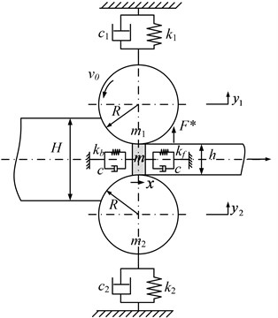
In Fig. 1, is the mass of rolled piece in roll gap, it can be obtained by the equation ; whereis the rolled piece density, is the volume of rolled piece in roll gap, and it may be approximately expressed as this: ; The wave force of rolled piece in the forward and backward sliding zones is equivalent to the force function. Its stiffness can be written as: , ; where and stand for forward and backward tension of rolled piece, and stand for forward and backward cross-sectional area of rolled piece, and stand for forward and backward deformation length of rolled piece caused by external tension. The damping effect between the roll and rolled piece is equal to two equivalent damping . and are respectively the equivalent mass of upper and lower rolls; and are respectively the equivalent stiffness of upper and lower rolls; and are respectively the equivalent dumping of upper and lower rolls;andare the vibration displacement of upper and lower rolls; is the roll radium; is the external disturbance force of rolls.
According to the Lagrange principle of generalized dissipation, the dynamic equilibrium equation of the roll in the vertical direction can be expressed as:
Based on the assumption that the structure and vibration characteristic of rolling mill is symmetrical in relation to rolling line, there exist ; ; ; . So, the two equations in Eq. (8) have same expression form. In order to simplify the analysis procedure, only research on the upper rolls. The equivalent mass of upper rolls is denoted by , the equivalent stiffness of upper rolls is denoted by , the equivalent dumping of upper rolls is denoted by . Based on the simplification and equivalence, Eq. (8) can be written as:
Based on the truth that in cold rolling process the roll is close to completely elastic flattening, namely, the contact surface between roll and rolled piece is close to a plane. On this basis, horizontal vibration dynamic equation can be expressed as:
By combining Eqs. (4, 7, 9, 10), coupling vibration equation of roll-rolled piece is obtained:
3. Coupling system solution of strip mill
Assuming that the system is subjected to periodic external disturbances, set . By transposition and replacement, Eq. (11) is transformed into a standard form:
where:
where:
Set, ; ; ; ; ; ; .
By parameters replacement, Eq. (12) becomes:
For finding a nonlinear approximate solution of Eq. (13), two time scales of and are selected. Then, the time derivatives are defined as:
where, , is small parameter. By using multiple scales method, set the solution of Eq. (14) as:
Substituting Eq. (14) and (15) into (13) and separating terms of each order of, one has:
The solution of Eq. (16) is setting as:
Substituting Eqs. (18) into (13), and system internal resonance is taken into account. By using the small scale detuning parameters, the frequencies are redefined as: . Where, and are detuning parameters. In order to avoid the secular terms of equations, Eq. (17) must satisfy the conditions as follow:
To solve Eq. (19), it is convenient to express the solution in polar form:
where, , , , both are the functions of . In order to obtain the solution of equation set, introducing intermediate variables , ; define that: ; ; Substituting , , , into Eq. (19), the modulation equations are expressed as:
Eliminating , , the frequency response is obtained in terms of two coupled equations as:
where:
4. Bifurcation characteristic analysis of strip mill
Substituting Eq. (21) into (22), and eliminating . Then the bifurcation equation is obtained:
where, , , , are the unfolding parameters related to the internal parameters of system; is the bifurcation parameter mainly related to external excitation. According to the Singularity theory, the Eq. (23) is the universal unfolding of the paradigm . Because there are too much unfolding parameters, the bifurcation characteristics cannot be directly displayed on the plane, so it is discussed in six cases.
Case 1: .
Bifurcation set: : Double limit point set: ;
Lag point set: ;
Transition set of system is: .
Fig. 2Transition set and bifurcation diagram of system when α1=α2=0
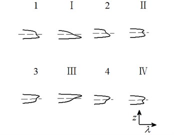
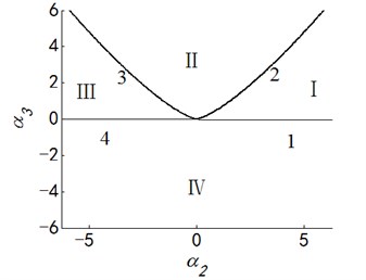
Case 2: .
Bifurcation set: ; Double limit point set: ;
Lag point set: ;
Transition set of system is: .
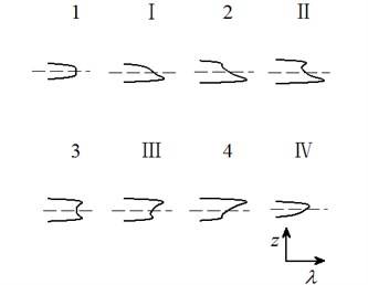
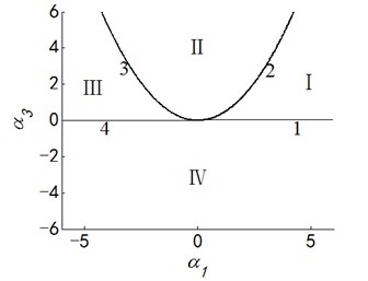
Fig. 3Transition set and bifurcation diagram of system when α1=α3=0
Case 3: .
Bifurcation set: ; Double limit point set: ;
Lag point set: ;
Transition set of system is: .
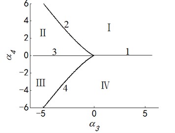
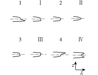
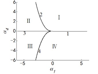
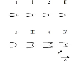
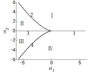
Fig. 4Transition set and bifurcation diagram of system when α1=α4=0
Case 4: .
Bifurcation set: ; Double limit point set: ;
Lag point set: ;
Transition set of system is: .
Fig. 5Transition set and bifurcation diagram of system when α2=α3=0
Case 5: .
Bifurcation set: ; Double limit point set: ;
Lag point set: ;
Transition set of system is: .
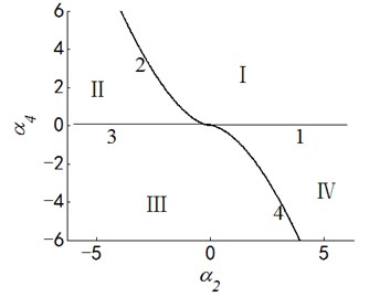
Fig. 6Transition set and bifurcation diagram of system when α2=α4=0
Case 6: .
Bifurcation set: ; Double limit point set: ;
Lag point set: ;
Transition set of system is: .
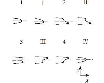
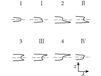
Letting two unfolding parameters of , , , equal to zero, six groups of projection of system transition sets are obtained accordingly. It can be seen from above six figures: on the same projection plane, it is divided into several different subregions by transition sets. In the same subregion, the bifurcation diagrams are all topological equivalent, and any points in different subregions are not equivalent. The system transition sets are divided into four subregions I, II, III, IV and four critical lines 1, 2, 3, 4. Selecting a point respectively in each subregions and the critical lines, then simulating their bifurcation characteristic in given system conditions, finally eight bifurcation diagrams are obtained. Simulation diagrams show that the system exhibits different bifurcation characteristics in different parameter regions. The eight groups of bifurcation diagrams indicate the change process of the system, which reflect the actual state of motion of the system. The analysis of bifurcation behavior can be used to determine the parameter region which leads to the instability of the system. Therefore, appropriate selection of system parameters can suppress the vibration of rolling mill.
Fig. 7Transition set and bifurcation diagram of system when α3=α4=0
5. Numerical simulation and analysis
Selecting the actual parameters of 1780 mm rolling mill of Chengde Iron and Steel Co., Ltd as an example. The characteristic of coupling vibration model is numerically analyzed. The corresponding system parameters in the model are shown in Table 1.
Table 1Parameters of rolling mill system
Parameters | Values |
Mass of up rolls () | 1.44×10⁵ kg |
Stiffness of up rolls () | 2.08×10¹⁰ N/m |
Damping of up rolls () | 1.04×10⁶ N·s/m |
Mass of rolled piece () | 0.6318 kg |
Forward stiffness of rolled piece () | 7.58×10⁷ N/m |
Backward stiffness of rolled piece () | 1.10×10⁸ N/m |
Damping of rolled piece () | 5.20×10³ N·s/m |
Width of rolled piece () | 1.5 m |
Amplitude of external excitation () | 0.5 MN |
Thickness of pre-rolling rolled piece () | 0.0145 m |
Entrance thickness of rolled piece () | 0.0141 m |
Exit thickness of rolled piece () | 0.0082 m |
Rotational speed of work roll () | 2.5 m/s |
Roll diameter () | 0.84 m |
Density of rolled piece () | 7.8×10³ kg·m-3 |
Forward tension of rolled piece () | 3.8 MPa |
Backward tension of rolled piece () | 5.5 MPa |
In this section, frequency responses of rolling system are analyzed. In order to investigate the efficiency of appropriate rolling parameters, comparisons between different nonlinear internal parameters and external excitation amplitudes are presented. Based on the coupling vibration Eq. (21) and (22), the frequency responses of rolling system are obtained, the results are shown as Fig. 8-9.
Fig. 8Frequency responses of system with different amplitudes of external excitation
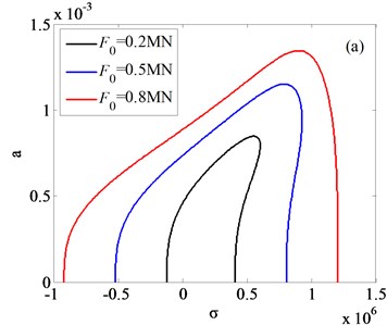
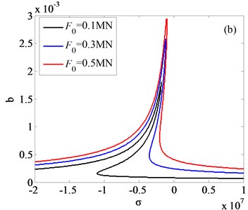
Fig. 9Frequency responses of system with different values of internal nonlinear parameters
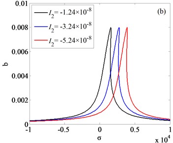
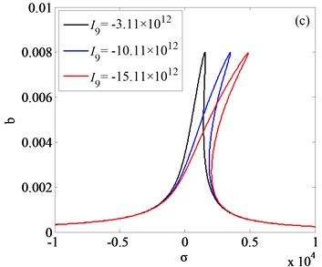
Fig. 8(a) and Fig. 8(b) is respectively the frequency response diagram of rolled piece and rolls. As is shown in Fig. 8, with the amplitudes changing of external excitation, the jump phenomenon is observed. In order to get the vibration rules of coupling system, three different external excitation amplitudes are compared in Fig. 8(a), 8(b), the results indicate that increasing the amplitude of the external excitation, the amplitude of the vertical vibration of the roll increases and the frequency domain of the jump phenomenon decreases. Vibration rules of the roll with the change of internal nonlinear parameters are shown in Fig. 9(a)-(c). By comparison and analysis, conclusion can be drawn: increasing the absolute value of the nonlinear parameter , the system becomes unstable, and frequency response in higher frequency disappeared; increasing the absolute value of the nonlinear parameter , the resonance frequency of the vertical vibration of the roll translates to the higher frequency, resonance frequency is far away from the natural frequency of the system; increasing the absolute value of the nonlinear parameter , the amplitude-frequency curve of roll vertical vibration migrates to the right, as the result, the unstable frequency region of the system increases.
6. Conclusions
In this paper, considering the relatively horizontal vibration of rolled piece, the friction coefficient is expressed as related with the vertical vibration displacement of roll and the horizontal vibration velocity of rolled piece. Furthermore, considering the dynamic interaction between roll and rolled piece, the coupling vibration model of strip mill is proposed. In order to analyze the characteristics of coupling system, the analytic solution of the coupling system is obtained by the multiple scales method. By numerical simulation and analysis, conclusions are obtained as follows:
1) According to the Singularity theory, six groups of transition sets and bifurcation diagrams of system are obtained. The results show that: with the bifurcation parameters changing, the system shows different stability. This paper proposed a method to avoid the unstable vibration of system by limiting the selection of rolling process parameters.
2) By using MATLAB simulation, the amplitude-frequency characteristics of system with different rolling parameters are analyzed. Simulation results indicate that: with the parameters changing, the “jump phenomenon” can be weakened or even avoided; The appearance of resonance in the system will be difficult. The results can be used as a theoretical basis for selecting parameters in engineering application, and also are of significance for design of strip mill systems.
References
-
Yildiz S. K., Forbes J. F., Huang B., et al. Dynamic modeling and simulation of a hot strip finishing mill. Applied Mathematical Modeling, Vol. 33, Issue 7, 2009, p. 3208-3225.
-
Fujita N., Kimura Y., Kobayashi K., et al. Dynamic control of lubrication characteristics in high speed tandem cold rolling. Journal of Materials Processing Technology, Vol. 229, 2015, p. 407-416.
-
Kim Y., Kim C. W., Lee S., et al. Dynamic modeling and numerical analysis of a cold rolling mill. International Journal of Precision Engineering and Manufacturing, Vol. 14, Issue 3, 2013, p. 407-413.
-
Brusa E, Lemma L. Numerical and experimental analysis of the dynamic effects in compact cluster mills for cold rolling. Journal of Materials Processing Technology, Vol. 209, Issue 5, 2009, p. 2436-2445.
-
Heidari A., Forouzan M. R. Optimization of cold rolling process parameters in order to increasing rolling speed limited by chatter vibrations. Journal of Advanced Research, Vol. 4, Issue 1, 2013, p. 27-34.
-
Yarita I., Furukawa K., Seino Y. Analysis of chattering in cold rolling for ultrathin gauge steel strip. Transactions of the Iron and Steel Institute of Japan, Vol. 18, Issue 1, 1978, p. 1-10.
-
Tamiya T., Furui K., Lida H., et al. Analysis of chattering phenomenon in cold rolling. Proceedings of the International Conference on Steel Rolling, Tokyo, Vol. 2, 1980, p. 1191-1202.
-
Johnson R., Qi Q. Chatter dynamics in sheet rolling. International Journal of Mechanical Sciences, Vol. 36, Issue 7, 1994, p. 617-630.
-
Liu F., Liu B., Liu H., et al. Vertical vibration of strip mill with the piecewise nonlinear constraint arising from hydraulic cylinder. International Journal of Precision Engineering and Manufacturing, Vol. 16, Issue 9, 2015, p. 1891-1898.
-
Yun I., Ehmann K., Wilson W., et al. Chatter in the strip rolling process. Part 3: chatter model. Journal of Manufacturing Science and Engineering, Vol. 120, Issue 2, 1998, p. 343-348.
-
Zhang Y., Yan X., Ling Q. Electromechanical coupling vibration of rolling mill excited by variable frequency harmonic. Advanced Materials Research, Vol. 912, Issue 914, 2014, p. 662-665.
-
Yang X., Tong C. N. Coupling dynamic model and control of chatter in cold rolling. Journal of Dynamic Systems Measurement and Control, Vol. 134, Issue 4, 2012, p. 271-277.
-
Peng Y, Zhang Y., Sun J., et al. Tandem strip mill’s multi-parameter coupling dynamic modeling based on the thickness control. Chinese Journal of Mechanical Engineering (English Edition), Vol. 28, Issue 2, 2015, p. 353-362.
-
Hu P., Ehmann K. A dynamic model of the rolling process. part I: homogeneous model. International Journal of Machine Tools and Manufacture, Vol. 40, Issue 1, 2000, p. 1-19.
-
Roberts W. Friction in the hot rolling of steel strip. Iron and Steel Engineer, Vol. 51, Issue 7, 1974, p. 56-62.
-
Yun I., Wilson W., Ehmann K. Review of chatter studies in cold rolling. International Journal of Machine Tools and Manufacture, Vol. 38, Issue 12, 1998, p. 1499-1530.
Cited by
About this article

This work is supported by the Natural Science Foundation of Hebei Province, China (Grant No. E2015203349).
Liu Bin contributed to the conception of the study and revised the manuscript; Jiang Jiahao contributed significantly to date analyses and wrote the manuscript; Liu Fei contributed to the manuscript preparation and programming; Liu Haoran revised the manuscript and provided fund support; Li Peng helped perform the analysis with constructive discussions.
