Abstract
Different types of non-linearity must be considered in solving the problem of determining the fatigue life of gas turbine engines rotors on the base of numerical methods. When turbomachinery rotors are simulated for assessment their fatigue life it is necessary take into account geometrical and physical nonlinearity of the model. As a result of partial steam or gas admission and edge tracks from stator blades it is important to consider the non-linear nature of the loads impacting on the rotor elements during the transient conditions of the work. While determining real stresses at the last stage of fatigue life assessment it is also necessary to take into account their non-linear nature.
1. Introduction
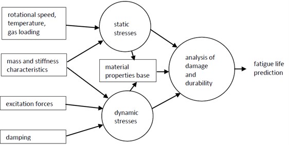
The assessment of fatigue life of gas turbine engines or steam-gas rotors requires follow-up of main stages [1, 2]:
1) The calculation of static stress. Calculation of natural frequencies and mode shapes, taking into account the rotation, uneven heating and gas forces. Their adjustment takes into account a mistuning [3, 4, 6-9, 15].
2) Numerical and experimental determination of the exciting load on the stationary and transient operating conditions. The main excitation sources for compressor and turbine rotor elements are perturbations due to partiality for supplying steam or gas and edge traces from stator blades.
3) An assessment of damping in material, structural damping, aerodynamic damping and damping from shock effects. A major role in turbines plays material and structural damping. The leading place in compressors belongs to the aerodynamic damping.
4) Calculation of a response on steady and unstable modes. Adjusted two or three-dimensional stress analysis in possible areas of stress concentration. Summation of static and dynamic stresses takes into account loading history.
5) Assessment of a fatigue life of rotor systems. Prediction of time of formation of a crack and destruction of constructions.
Solution of the problem of blade structures fatigue life assessment can be represented by scheme on Fig. 1.
2. Considering of geometrical and physical nonlinearity
The statics equation in finite element method for constant speed of rotation and temperature is:
where – a stiffness matrix, – the supplementary stiffness matrix arising from rotation, – a matrix of a geometrical stiffness, – node displacements, – vectors of temperature and centrifugal loadings.
In case of the free vibration without damping we have [5]:
where – Coriolis matrix and [] – mass matrix.
For taking into account physical nonlinearity of the stress-strained state of structures there are two main theories: the straining theory of plasticity and the theory of a current. The equations of the straining theory of plasticity establish connection between stresses and deformations, and the equations of the theory of a current - between infinitely small increments of these values. In case of a simple loading both theories give identical result, however, for a number of tasks, for example, for a problem of a thermo plasticity, the theory of a current reflects loading history more fully. We find a solution of the Eq. (1), (2) according to iteration algorithm [1, 5, 10].
Fig. 1Assessment of fatigue life scheme
3. Considering of nonlinearity in determination of real stresses
For calculation of fatigue life, it is necessary to find real, but not elastic stresses. It is possible to execute it by means of numerical methods, for example, by the technique described in [12]. But this technique requests considerable computing resources (time, memory). Far less resources are requested by the so-called Neuber rule [12, 13] describing connection between elastic and real stresses and deformations (Fig. 2):
Fig. 2Recalculation of elastic stresses in elastic-plastic (Neuber rule)
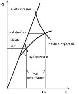
Local elastic stresses from equations for deformation and stresses can be recalculated into real elastic – plastic deformations (Fig. 2) where – amplitude of variable deformations:
Constants and turn out from the experimental coefficients of vibration strength, and and as well as an exponent and [14]:
It is possible to apply damageability parameters to the considering of a relaxation and creep, for example, on Morrow [13]:
Further from work [14]:
with , and .
To find from the Eq. (8) real stresses, it is necessary to know real deformation. For this purpose it is possible to use a technique of Rieger [14], which possesses an essential shortcoming, namely – need of the experimental determination of cycle parameters for each material. In this regard it is obviously necessary to use other dependence – the empirical formula of Manson connecting a range of the complete deformation and number of cycles before destruction [10]. Using the assumption of the linear relation of fatigue strength from average stress () and in view of asymmetry of a cycle, we will receive [10]:
where – contraction ratio in %, and – temperature of a cyclic deformation.
Birger I. A. suggested to lead Eq. (9) to a look:
where – an exponent of fatigue curve.
At expression is used:
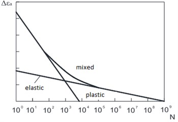
The total deformation (Fig. 3) is the sum of elastic and plastic components which are schematically represented in Fig. 4.
Change of stresses and deformations ranges from cycle to cycle comes to an end through rather small number of cycles, and the main decrease in fatigue life happens at the stabilized state (constant ranges of stresses). Thus, ranges of stresses or deformations of the stabilized state are used in calculations. After calculation and substitution in the Eq. (3) it is possible to receive the real stresses (Fig. 2).
Fig. 3Diagram “stress-deformation”
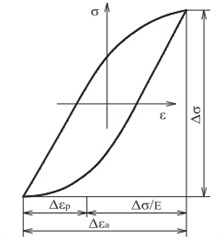
Fig. 4Summing of elastic and plastic deformation
4. Numerical results
For the complex spatial structures like compressor fan blade with curvilinear fixing it is necessary to consider a non-linear geometrical stiffness in conditions of centrifugal stresses in the median plane. One of such blades model is presented in Fig. 5. Input data: an elastic modulus 1,1×10⁵ MPa; density 4,54×10³ kg/m3; a Poisson’s ratio – 0,3; rotation speed 1121 s-1. On a transition curve of a blade profile part to a disk rim rigid fixing is simulated. The results of calculations in the linear and geometrically non-linear statements are given in Fig. 6. Decrease in the maximal stresses for pressure side of blade approximately for 10 % is noted. For geometrically non-linear decision the maximal stresses in this area are 122×107 Pa, lengthening and the angles of elastic promotion of a blade at the same time decreased more, than twice.
Fig. 5Finite element model of blade
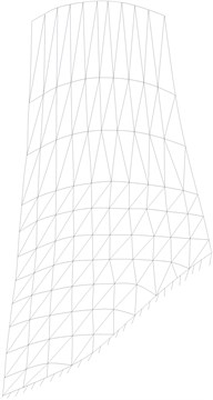
Fig. 6Stresses in wide blade (- linear, - - - non-linear solution)
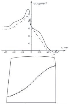
a) Pressure side
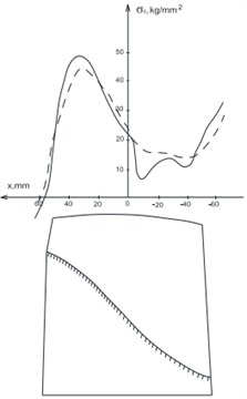
b) Back
The second example – a cooled blade of the helicopter gas-turbine engine impeller. Mechanical characteristics of a blade: density 8,4×10³ kg/m3; a Poisson’s ratio – 0,3; the elastic modulus 2,135×105 MPa. The effect of geometrical nonlinearity consideration under maximal rotation speed was analyzed. Decrease of natural frequencies under speed increasing is noted. That it is connected with existence of the compression sections on a blade back (Table 1).
Table 1Research results
Vibration mode | 0 | 717 s-1 | |
Linear | With geometrical non-linearity | ||
1830,7 | 2149,0 | 2097,2 | |
1913,6 | 2183,4 | 2178,1 | |
4054,6 | 4061,1 | 3993,5 | |
5225,1 | 5428,4 | 5413,2 | |
6511,2 | 6834,7 | 6886,5 | |
5. Conclusions
The efficient technique is developed for an assessment of fatigue life of gas turbine engines rotors being under heavy static and cyclic loads causing a low-cyclic and multi-cycle material fatigue during the work. This technique is developed taking into account geometrical nonlinearity of finite element model, physical nonlinearity of material and non-linear effects during the transient conditions of the work. The technique was successfully tested on test models and real constructions [1-5, 10-12] that means its operability.
References
-
Repetckii O. V. Automation of Strength Calculations of Turbomachines. Irkutsk Publishing House, Irkutsk, 1990, p. 100, (in Russian).
-
Repetckii O. V., Buy Man Kyong A question of the choice of a numerical method of the analysis of stresses at an assessment of a multi-cycle fatigue of blades of transport turbomachines. News of IGEA, Vol. 6, 2010, p. 153-158, (in Russian).
-
Repetckii O. V., Do Man Tung Mathematical model operation and numerical analysis of vibrations of ideal cyclic and symmetric systems finite element method. IGEA News, Vol. 3, 2012, p. 149-153, (in Russian).
-
Repetckii O. V., Do ManTung Investigation of the characteristics of mistuned turbomachinery bladed discs vibration based on the reduced-order modeling by finite element method. Bulletin SibSAU, Vol. 1, Issue 53, 2014, p. 60-66, (in Russian).
-
Repetckii O. V. Computer Analysis of the Dynamics and Strength of Machines. Irkutsk State Technical University Publishing House, Irkutsk, 1999, p. 301, (in Russian).
-
Beirow B. Grundlegende Untersuchungen zum Schwingungsverhalten von Verdichterlaufrädern in Integralbauweise. Shaker Verlag, Aachen, 2009.
-
Klauke T. Schaufelschwingungen Realer Integraler Verdichterräder im Hinblick auf Verstimmung und Loaklisierung. Der Andere Verlag, Cottbus, 2008.
-
Maywald T., Beirow B., Kühhorn A. Mistuning und Dämpfung II. FVV Abschlussbericht, 2014.
-
Maywald T., Beirow B., Kühhorn A. Mistuning und Dämpfung II. FVV Informationstagung Turbomaschinen, 2014.
-
Heiman B., Gerdt V., Popp K., Repetckii O. V. Mechatronics: Components, Methods, Examples. Publishing House of the SB RAS, Novosibirsk, 2010, p. 602.
-
Zainchkovsky K. S., Repetckii O. V. Sensitivity Analysis of Gas Turbine Engine Blades by Finite Element Method. Intercollege Scientific Collection IrSTU “The Asymptotic Methods in Problems of Aerodynamics and Design of Aircraft”, Irkutsk State Technical University, Irkutsk, 1996, p. 83-88, (in Russian).
-
Irretier H., Repetski O. Vibration and Life Estimation of Rotor Structure. IFToMM Conference on Rotor Dynamics, Darmstadt, 1998.
-
Kayser A. Entwicklung eines Programmes zur Lebensdauer berechnung von Turbinenschaufeln. B.Sc. Thesis, Institute of Mechanics, University of Kassel, Kassel, 1990, p. 110.
-
Rieger N. F., Steele J. M., Lara T. C. T. Turbine blade life prediction computer program. Proceedings of EPRI Workshop on Steam Turbine Blade Reliability, 1982.
-
Wei S. T., Pierre C. Localization phenomena in mistuned assemblies with cyclic symmetry. Part 1: Free vibrations. Journal of Vibration, Acoustics, Stress, and Reliability in Design, Vol. 110, Issue 4, 1987, p. 429-438.
About this article

