Abstract
Taken a gas turbine rotor system as the research object, this paper has established dynamical model based on transfer matrix method. Natural vibration characteristics are solved with different transfer matrix models, and are compared with that gotten by finite element method. Then unbalanced response is researched. The effects of eccentric factors are discussed on unbalanced vibration. Furthermore, the application is explored in rotor dynamic balancing. The results show there is much minor deviation between natural frequencies of transfer matrix method and finite element method, and vibration modes of two methods coincide quite well. It illustrates the model established in the research is reliable. For input side of blade-disk rotor, unbalanced vibration occurs more easily in lower frequency. While unbalanced vibration of output side is more sensitive at higher frequency. With the increase of eccentric mass, unbalanced vibration of blade-disk rotor is more heavily, and the displacement rotates around a fixed node. The application of opposite unbalanced mass can decrease the amplitude of vibration in lower frequency. Hence, it can be used to achieve the balance of rotor dynamics. This research provides the theoretical basis and technological fundament for gas turbine rotor dynamics design.
Highlights
- Taken a gas turbine rotor system as the research object, this paper has established dynamical model based on transfer matrix method.
- Natural vibration characteristics are solved with different transfer matrix models, and are compared with that gotten by finite element method.
- Unbalanced response is researched. The effects of eccentric factors are discussed on unbalanced vibration.
1. Introduction
As one of the key basic industry equipment, gas turbine is widely applied in many fields including aeronautical engineering, shipping transport, electric power and so on. With the development of gas turbine technology, work efficiency and reliability are improved further. This makes rotational speed and load of blade-disk rotor system increase highly. Because of the higher rotational speed and load, the phenomena of vibration and instability are caused in gas turbine operation. Additionally, modern gas turbine rotor is generally working in a state of supercritical speed. Heavy vibration caused by unbalance factors would make rotor system in the fatigue damage. It has a serious effect on the stability and lifetime of rotor working. Hence, more and more scholars begin to pay close attention to vibration characteristics of gas turbine blade-disk rotor system.
For the rotor of gas turbine, related dynamic problems have been analyzed in previous studies. Taplak et al. [1] modeled a gas turbine rotor with certain geometrical and mechanical properties, and dynamic analysis was made by finite element method (FEM). Yuan et al. [2] developed the improved 2-D FEM by considering the contact effects and pre-tightening forces. Dynamic characteristics of gas turbine rotors were calculated with satisfying accuracy and less time. Chung et al. [3] developed the dynamic analysis method using commercial S/W, and identified the limitations in application of rotor dynamics module. Campbell diagram, Lee diagram, mode shapes and critical speeds were computed for the small-size gas turbine engine rotor. Pirogova [4], Gong [5] and Gao [6] et al. investigated the rotor mode and critical speed of a gas turbine with FEM calculation. The effects of bearing stiffness and contact stiffness were studied on natural vibration of rotor system. Mei [7] and Guan [8] et al. adopted SAMCEF software to analyze the rotor dynamics of gas turbine. The stability and reliability of rotor system were proved in operation process. Lu et al. [9] established the finite element model of a disk rotor in FEM software, natural frequencies were analyzed under contact effects and rod preloads. Ogbonnaya [10] carried out the modeling and simulation of gas turbines rotor shaft faults, artificial neural networks were integrated into the monitoring of essential performance parameters in gas turbine operations. Applying balancing theory with low speed and multiple planes, Deng et al. [11] achieved the balancing experiment of high-speed gas turbine rotor system.
In addition, some scholars developed the research on blade-disk vibration of gas turbine [12-15]. Zhao et al. [16] made the modal analysis of a certain gas turbine blade-disk based on introduced FEA method. Vibration characteristics of each natural mode and corresponding influence were discussed in detail. Zhou et al. [17] studied the vibration characteristics of following elements and components, including a single blade, a turbine disk, a blade-disk coupled system and shrouded blades. Thomas [18] and Zhang [19] et al. applied the basic finite element model of periodic blade-disk structure to eliminate internal degrees of freedom. A vibration analysis for the coupled system was processed by wave transmittal technique. Fu et al. [20] presented the computing method of cyclic symmetric structures, and calculated the natural vibration characteristics of a gas turbine blade-disk. Petrov et al. [21] performed the numerical investigations to demonstrate the capabilities of new blade-disk damper models, and analyzed the influence of damper parameters on the forced response.
Summing up the related literatures, it is found more scholars use FEM to analyze the natural vibration characteristics of gas turbine rotor system and blade-disk system respectively. While there is less research on the unbalance response and dynamic balancing of integrated blade-disk rotor system. In addition, due to the complexity of gas turbine blade-disk rotor, the number of elements and nodes is extremely large for FEM calculation. This causes that numerical analysis requires a lot of computer resources, and it is even difficult to calculate in some cases. Hence, the efficiency and accuracy of numerical analysis can’t be guaranteed. For the problem of rotor dynamics, transfer matrix method is one of quick and effective approach. In the process of transfer matrix calculation, the dimension of matrix does not increase with the increase of system degree of freedom. Meanwhile the program is convenient to realize, and the small storage unit is required. So, transfer matrix method is widely used in the dynamic analysis of complex rotating machinery.
A gas turbine rotor system is taken as the research object, this research establishes dynamical model of integrated blade-disk rotor based on transfer matrix method. Natural vibration characteristics are solved with different transfer matrix models. The results are compared with that gotten by finite element method to verify the reliability of analysis model. Then unbalanced response characteristics are analyzed. The effects of eccentric factors are discussed on unbalanced vibration. Furthermore, the application is explored in rotor dynamic balancing.
2. The establishment of dynamic model
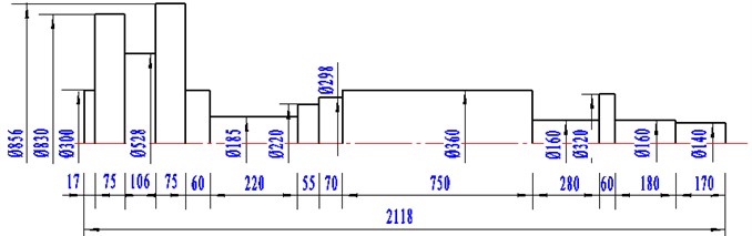
According to engineering drawings and technical parameters of gas turbine YLII-12000/32A, two dimensional model of blade-disk rotor system is obtained by simplifying part of the structure. Specific sizes are as shown in Fig. 1, the unit of length is millimeter.
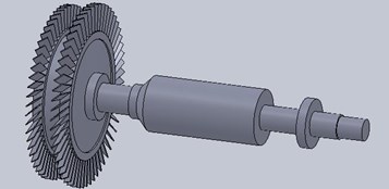
Based on two dimensional sizes of gas turbine rotor system, three dimensional model is established with SolidWorks software. In the process of modeling, the integration of blade-disk rotor is achieved to make the model closer to engineering practice. Three dimensional model of blade-disk rotor system is as shown in Fig. 2.
In blade-disk rotor of gas turbine, rotor material is alloy steel 40CrNiMoA, elasticity modulus is 113 GPa, the density is 4370 kg/m3, Poisson’s ratio is 0.3. The material of blade and disk is high-temperature alloy GH864, elasticity modulus is 112 GPa, the density is 4680 kg/m3, Poisson’s ratio is 0.27.
Fig. 1Two dimensional model of blade-disk rotor system
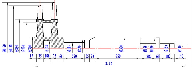
Fig. 2Three dimensional model of blade-disk rotor system
2.1. Equivalent modeling of blade-disk rotor system
The structure of gas turbine blade-disk rotor is complicated. If transfer matrix method is adopted to calculate it, further simplification of the model is required. Based on three dimensional model of blade-disk rotor and the equal principle of rotational inertia, parts of blade-disk rotor are simplified into disks and shafts. Now taking the blades as an example, the process of simplification is illustrated.
According to the parameters of blade-disk rotor, it is consisted of 57 blades. Applying the equal principle of rotational inertia, blades are simplified into hollow cylinder as shown in Fig. 3.
Fig. 3Parameter diagram of hollow cylinder
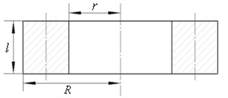
In Fig. 3, is outer diameter of designed hollow cylinder, is inner diameter of designed hollow cylinder, is the length of designed hollow cylinder. The steps of equivalent calculation are as follows:
where is the number of blades, is the length of blade, is the mass of blade, is the distance between gravity center of blade and the axis of rotor, is total mass of designed hollow cylinder, , and are shape parameters of designed hollow cylinder.
Based on the above process, related hubs and shafts are simplified. The final equivalent blade-disk rotor is obtained as shown in Fig. 4, the unit of length is millimeter.
2.2. The establishment of transfer matrix model
Transfer matrix model can be divided into two types: lumped mass model and distributed mass model. Lumped mass model is the model with limited degree of freedom. Without changing the original elasticity of rotor system, the mass and rotational inertia are concentrated on several nodes. While in distributed mass model, blade-disk rotor is simplified as the combination of distributed mass shafts, and is linked by several nodes along the axis.
Fig. 4Two dimensional model of simplified blade-disk rotor
2.3. Lumped mass model
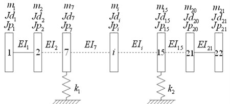
For establishing the model of lumped mass, blade-disk rotor is simplified further. Related equivalent parameters of disks and shafts are obtained including the equivalent of mass , equatorial rotational inertia , polar rotational inertia and shaft stiffness , elastic support stiffness and . Lumped mass model of blade-disk rotor is shown in Fig. 5.
Fig. 5Lumped mass model of blade-disk rotor system
2.4. Distributed mass model
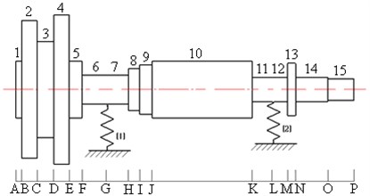
Based on physical structure size of gas turbine blade-disk rotor, it can be simplified as 2 elastic supports and 15 shafts to construct the model of distributed mass. Each part has been marked with number symbols, as are shown in Fig. 6.
Fig. 6Distributed mass model of blade-disk rotor system
3. Natural vibration characteristics of blade-disk rotor
3.1. Calculation of natural frequencies
Assuming that support stiffness is isotropic, state vectors of gas turbine blade-disk rotor are simplified as:
where is the linear displacement, is the angular displacement, is the bending moment, is the shearing force. According to lumped mass model and distributed mass model, the boundary conditions are as follows:
So, the initial state vector can be expressed:
Transfer relationship from the left end to the right end of blade-disk rotor system is:
Defining transfer matrix , Eq. (5) is simplified as:
So, there are:
According to transfer matrix model of gas turbine blade-disk rotor, boundary conditions at the end section are:
The end section state vector is:
Hence, it is obtained:
It is further simplified as:
When homogeneous algebraic equation set has a nonzero solution, its coefficient determinant is equal to zero. So, frequency equation of rotor system is:
Solving the above frequency equation, rotor critical frequency of gas turbine can be obtained. Critical frequencies of each order and differences between lumped mass model and distributed mass model are exhibited in Table 1 and Fig. 7.
Table 1Difference analysis of two models
Order | Lumped mass model / rad.s-1 | Distributed mass model / rad.s-1 | Absolute differences | Relative differences |
1 | 115.09 | 115.02 | 0.07 | 0.06% |
2 | 228.91 | 227.88 | 1.03 | 0.45% |
3 | 286.38 | 280.65 | 5.73 | 2.00% |
4 | 878.07 | 835.04 | 43.03 | 4.90% |
5 | 1606.99 | 1528.97 | 78.02 | 4.86% |
By comparison, it can be found that relative differences of natural frequencies in the former five orders are all within 5 %. Lumped mass model is consist of several massless elastic shafts and lumped mass nodes. While in distributed mass model, blade-disk rotor is discretized into a few of homogeneous shafts with equal cross sections. Comparing with two models, lumped mass model is convenient to solve, and has much higher efficiency. So lumped mass model is adopted in further analysis.
Fig. 7Natural frequencies comparison of two models
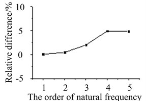
a) Difference trend of 1st-5th order
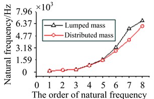
b) The comparison of natural frequencies
3.2. Comparison of blade-disk rotor modes
Vibration mode can be solved when obtaining critical frequency of blade-disk rotor. Boundary conditions are as follows:
From the Eq. (13), relationship between initial parameters and can be obtained:
In Eq. (14), .
Substituting critical frequency of rotor system, the Eq. (10) is transferred as:
By the Eq. (15), proportional relation of line displacement and angular displacement is calculated in each section. This is mode shape corresponding to the critical frequency. Assuming , the normalized vibration mode can be obtained.
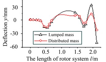
Mode shapes obtained by two models are compared, typical order vibration curves are shown in Fig. 8.
Fig. 8 shows that vibration curves of two modes coincide quite well, especially in the low order. It proves the results of two models are reliable.
Fig. 8Vibration curves in typical orders
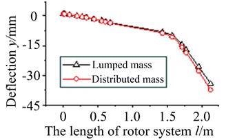
a) The 2nd order
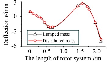
b) The 4th order
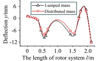
c) The 6th order
d) The 8th order
3.3. Verification of finite element method
Based on finite element method, natural frequencies of blade-disk rotor are calculated. Critical frequencies in the former five orders are compared between transfer matrix method and finite element method, as are shown in Table 2 and Fig. 9.
Table 2Comparison with finite element results
Order | Transfer matrix method / Hz | Finite element method / Hz | Relative differences |
1 | 115.09 | 118.26 | 2.68 % |
2 | 228.91 | 232.17 | 3.26 % |
3 | 286.38 | 288.63 | 0.78 % |
4 | 878.07 | 895.68 | 1.97 % |
5 | 1606.99 | 1688.00 | 4.80 % |
As can be seen from Table 2, the calculated natural frequencies have a minor deviation. It is mainly because of the model difference between transfer matrix method and finite element method. While relative difference of each order frequency is within 5 %.
In order to further verify the accuracy of two methods, mode shapes of typical orders are extracted for comparison, as shown in Fig. 9.
In Fig. 9, displacement nephograms are obtained by the analysis of finite element method. Vibration curves are plotted by the calculation of transfer matrix method. By the comparison of vibration modes, it can be found that the peak and valley of mode shapes are basically consistent between transfer matrix method and finite element method. This further verifies the reliability of transfer matrix model established in the research.
Fig. 9Modal shape comparison of transfer matrix method and finite element method
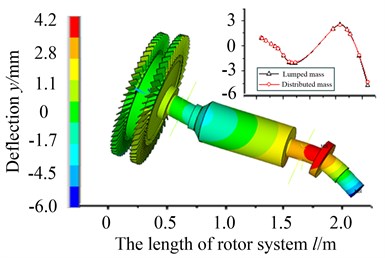
a) The 4th modal order
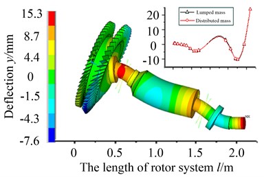
b) The 5th modal order
4. Analysis and discussion of unbalanced response
4.1. Solution of unbalanced response
Assuming that there are eccentric mass and eccentric distance on blade-disk rotor of gas turbine. It can be equivalent to an unbalanced force acting on the disk. Centrifugal stress caused by mass eccentricity is:
If , Eq. (17) can be simplified as:
where is the moment of unbalanced mass, is rotational speed of blade-disk rotor.
State vector transfer relationship between two sides of the disk is expressed as:
If adding a shaft segment on its right side, the state vector relationship between two sides is:
According to transfer matrix model, the recursion of state vectors starts from the leftmost section of balde-disk rotor system. The process is similar to the calculation of critical speed. State vector of the section is:
The elements of matrix , are obtained by the multiplying of transfer matrixes in each component. For the cross section at the right end, boundary conditions are considered. So, it is obtained:
It is further simplified as:
Based on Eq. (23), and are solved at the left end of starting section. Then substituting into Eq. (21), state vector is obtained at each section, it is the unbalanced response of blade-disk rotor.
4.2. Effects of eccentric factor on unbalance response
Assuming that eccentric mass is 0.2 kg, eccentric distance is 0.5 m, rotational speed is 5800 r/min on blade-disk rotor of gas turbine. For the following cases, effects of eccentric factor on the unbalanced response are discussed.
4.2.1. The position of eccentric mass
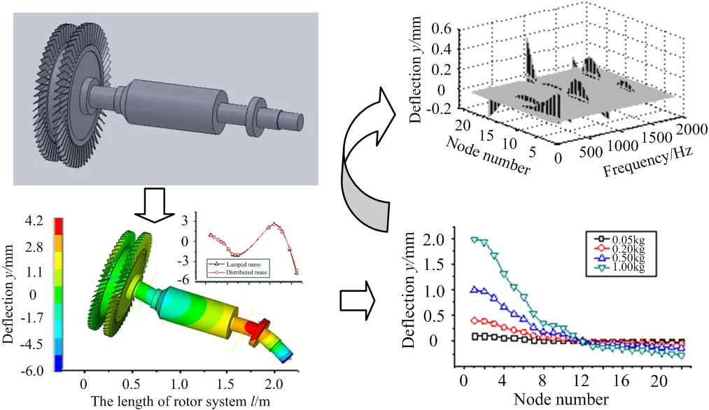
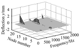
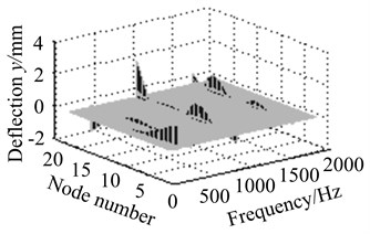
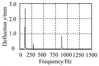
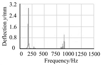
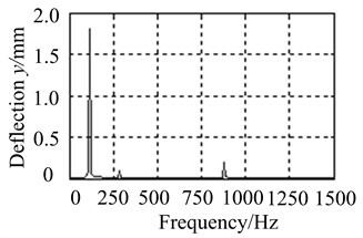
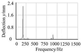
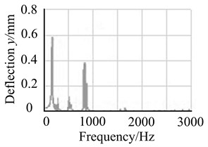
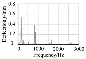
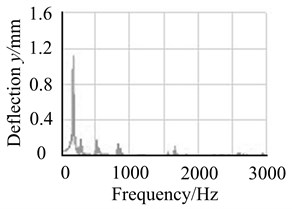
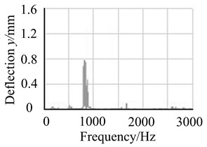
1) Assuming that eccentric mass is on node 4, response results are discussed at different working frequencies, as are shown in Fig. 10.
From Fig. 10(a)-(d), it is found node 2 and node 4 vibrate most heavily at the first order frequency. With the increasing of frequency, resonant amplitude does not appear higher peak value. It illustrates that input side vibrates more easily at low frequencies. The amplitude of node 11 is highest near the frequency of 1000 Hz, and is relatively small in the low and high order frequencies. It indicates shaft section between bearing supports vibrates mainly in the middle frequencies. The amplitude of node 18 is much smaller in the low frequencies. With the increasing of frequency, vibration amplitude increases gradually. It denotes output side is more sensitive in the high frequencies.
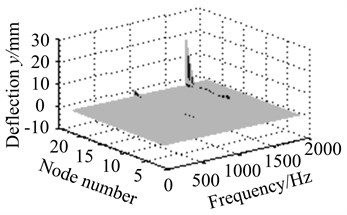
2) Assuming that eccentric mass is respectively on node 2, node 4, node 11 and node 18, response results are discussed at different working frequencies, as is shown in Fig. 11.
Figs. 11(a)-(d) show response amplitude is minimum when eccentric mass is on node 4 near bearing supports. Output side vibrates most heavily on node 18 at the higher frequencies. It denotes rotor supports take an important effect on unbalance response.
Fig. 10Vibration curves at different working frequencies
a) The response of node 2
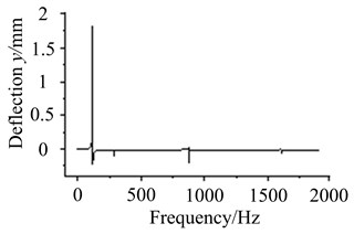
b) The response of node 4
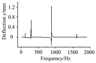
c) The response of node 11
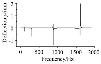
d) The response of node 18
Fig. 11Vibration curves at different eccentric positions
a) Eccentric mass on node 2

b) Eccentric mass on node 4
c) Eccentric mass on node 11
d) Eccentric mass on node 18
4.2.2. The size of eccentric mass
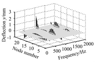
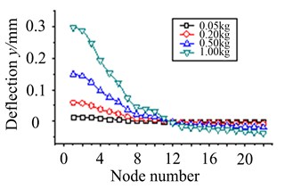
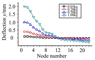
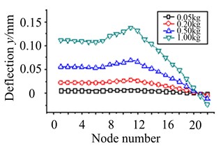
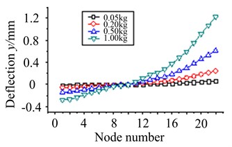
1) Assuming that eccentric mass is on node 2, node 4, node 11 and node 18, working speed is 5800 r/min. Unbalance response of each node is solved when the size of eccentric mass is respectively 0.05 kg, 0.2 kg, 0.5 kg and 1 kg, as are shown in Fig. 12.
From Fig. 12(a)-(d), it is exhibited that each node of blade-disk rotor rotates around a fixed node with the increasing of eccentric mass size, and the displacement of each node gradually increases. While the position of eccentric mass is different, the fixed rotating node will change. In addition, node displacement is much larger when eccentric mass is on node 4. It illustrates the part of node 4 has a high sensitivity to eccentric mass.
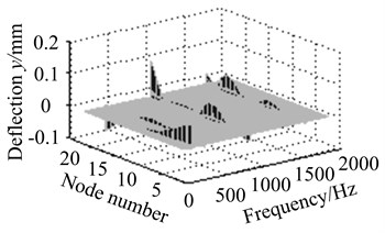
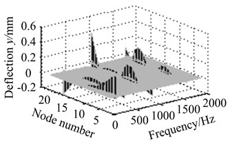
2) Assuming that eccentric mass is on node 4, unbalance response of each node is solved at different working frequencies, when the size of eccentric mass is respectively 0.05 kg, 0.2 kg, 0.5 kg and 1 kg. As are shown in Fig. 13.
Fig. 12The effect of eccentric mass size at working speed
a) Eccentric mass on node 2
b) Eccentric mass on node 4
c) Eccentric mass on node 11
d) Eccentric mass on node 18
Fig. 13The effect of eccentric mass size at different working speed
a) Eccentric mass 0.05 kg
b) Eccentric mass 0.2 kg

c) Eccentric mass 0.5 kg
d) Eccentric mass 1 kg
Fig. 13(a)-(d) show resonance peak of blade-disk rotor increases with the increasing of eccentric mass size. It indicates that the greater eccentric mass is, the more serious unbalanced response will be.
4.2.3. Comparison with finite element results
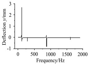
Transfer matrix method and finite element method are respectively applied to solve the unbalanced response of blade-disk rotor system, and the results of two methods are analyzed and compared as shown in Fig. 14(a)-(b).
Figs. 14 and 15 show peak value and peak frequency of unbalanced response obtained by transfer matrix method are well consistent with the results obtained by finite element method. It verifies the reliability of calculation method in this research.
Fig. 14Comparison of unbalanced response on node 2
a) Transfer matrix method
b) Finite element method
Fig. 15Comparison of unbalanced response on node 4
a) Transfer matrix method
b) Finite element method
4.3. Effects of eccentric factor on unbalance response
For providing a theoretical basis to determine the way of weighting, judge the unbalanced position and select the weighted surface in the actual dynamic balancing, response analysis of blade-disk rotor is carried out with multiple unbalance. Assuming that eccentric mass is 0.2 kg, eccentric distance is 0.5 m, rotational speed is 5800 r/min, the following four cases are analyzed:
(1) Only blade-disk 1 with eccentric mass;
(2) Only blade-disk 2 with eccentric mass;
(3) Blade-disk 1 and 2 with eccentric masses in same direction;
(4) Blade-disk 1 and 2 with eccentric masses in opposite direction.
By analysis, unbalanced responses of blade-disk rotor on node 4 are obtained in four cases. The comparison of response curves is shown in Fig. 16.
It can be found from Fig. 16 that response amplitude of the lower order frequency is obviously increased, and response amplitude of the higher order frequency is reduced when there are eccentric masses on blade-disk 1 and 2 in same direction. However, response amplitude of the lower order frequency is obviously controlled, and response amplitude of the higher order frequency is increased if there are eccentric masses on blade-disk 1 and 2 in opposite direction.
For the blade-disk rotor of gas turbine in this research, rotational speed is 5800 r/min, working frequency is 96.67 Hz in the range of low frequency. Hence, in order to reduce the impact of unbalance on the stability of blade-disk rotor, the same size of reverse unbalance mass should be imposed in the corresponding position. This can decrease the amplitude of vibration, and achieve the purpose of rotor dynamic balancing.
Fig. 16Unbalanced responses of bade-disk rotor in each case
a) Only blade-disk 1 with eccentric mass
b) Only blade-disk 2 with eccentric mass
c) Blade-disk 1 and 2 with eccentric masses in same direction
d) Blade-disk 1 and 2 with eccentric masses in opposite direction
5. Conclusions
This research has established dynamical model based on transfer matrix method. Natural vibration characteristics are solved with different transfer matrix models, and are compared with that gotten by finite element method. Then unbalanced response is researched. The effects of eccentric factors are discussed on unbalanced vibration. Furthermore, the application is explored in rotor dynamic balancing. The results show:
1) The deviation is much minor between natural frequencies of transfer matrix method and finite element method. Relative differences of natural frequencies in the former five orders are all within 5 %. And vibration modes of two methods coincide quite well. It illustrates the model established in this research is reliable.
2) For input side of blade-disk rotor, unbalanced vibration occurs more easily in lower frequency. While unbalanced vibration of output side is more sensitive at higher frequency. With the increase of eccentric mass, unbalanced vibration of blade-disk rotor is more heavily, and the displacement rotates around a fixed node.
3) The application of opposite unbalanced mass can effectively suppress the amplitude of vibration in lower frequency. While the application of same unbalanced mass can decrease vibration amplitude in higher frequency. Working speed of gas turbine blade-disk rotor is in the range of lower frequency, so opposite unbalanced mass can be taken to achieve the balancing of rotor dynamics.
References
-
Taplak H., Parlak M. Evaluation of gas turbine rotor dynamic analysis using the finite element method. Measurement, Vol. 45, Issue 5, 2012, p. 1089-1097.
-
Yuan Qi, Gao Rui, Feng Zhenping, Wang Jianlu, et al. Analysis of dynamic characteristics of gas turbine rotor considering contact effects and pre-tightening force. Proceedings of the ASME Turbo Expo, Vol. 5, 2008, p. 983-988.
-
Chung H. J., Lee C. W., Hong S. W., et al. Dynamic analysis of the small-size gas turbine engine rotor using commercial S/W and its limitations. Journal of Phycology, Vol. 48, Issue 1, 2010, p. 254-260.
-
Radionov A. A., Pirogova N. S., Taranenko P. A. Calculative and experimental analysis of natural and critical frequencies and mode shapes of high-speed rotor for micro gas turbine plant. Procedia Engineering, Vol. 129, 2015, p. 997-1004.
-
Gong Jianzheng, Zhong Fangming, He Xing, et al. Mode analysis and critical speed calculation on a low-pressure compressor rotor of marine gas turbine based on ANSYS. Modern Manufacturing Engineering, Vol. 4, 2012, p. 73-77.
-
Gao Rui, Yuan Qi, Gao Jin A study of a finite element model for a gas turbine tie-rod rotor and its critical speed calculation. Journal of Engineering for Thermal Energy and Power, Vol. 24, Issue 3, 2009, p. 305-308.
-
Mei Qing The critical speed analysis with SAMCEF/ROTOR using two dimensional model. Gas Turbine Experiment and Research, Vol. 16, Issue 3, 2003, p. 42-44.
-
Guan Qi, Jin He, Xin Li Analysis on rotor dynamic of the low turbo compressor. Ship Science and Technology, Vol. 32, Issue 251, 2010, p. 129-134.
-
Lu Mingjian, Geng Haipeng, Yang Baisong, et al. Finite element method for disc-rotor dynamic characteristics analysis of gas turbine rotor considering contact effects and rod preload. IEEE International Conference on Mechatronics and Automation, 2010, p. 1179-1183.
-
Ogbonnaya E. A. Dynamic modeling of gas turbine rotor shaft faults. Marine Technology, Vol. 46, Issue 3, 2009, p. 155-164.
-
Deng Yong The high speed dynamic balance for rotor of MS9001E gas turbine. Gas Turbine Technology, Vol. 19, Issue 1, 2006, p. 68-72.
-
Armstrong E. K. An Investigation into the Coupling between Turbine Disc and Blade Vibrations. Ph.D. Thesis, University of Cambridge, 1955.
-
Bishop R. E. D., Mclead A. J. The forced vibration of circular flat plates. Mechanical Engineering Science Monogragh, 1965, p. 231-238.
-
Irreiter H. Coupled vibrations of blades in bending-bending-torsion and disks in out-of-plane and in-plane motion. Proceedings of the ASME Turbo Expo, Vol. 5, 1979, p. 524-533.
-
Liang M., Wang B., Yan T. Dynamic optimization of robot arm based on flexible multi-body model. Journal of Mechanical Science and Technology, Vol. 31, Issue 8, 2017, p. 3747-3754.
-
Zhao Weiqiang, Liu Yongxian, Lu Mowu FEA on vibration characteristics of a gas turbine blade-disc. Advanced Materials Research, 2012, p. 731-734.
-
Zhou Chuanyue, Zou Jingxiang, Wen Xueyou Analysis of the vibration characteristics of a gas turbine bladed disc. Journal of Engineering for Thermal Energy and Power, 2000, p. 205-209.
-
Thomas D. L. Dynamics of rotationally periodic structures. International Journal for Numerical Methods in Engineering, Vol. 1, Issue 14, 1979, p. 81-102.
-
Zhang Dayi, Shi Yajie, Lin Li, et al. Model analysis of bladed disk coupled system of compressor with low aspect ratio. Beijing University of Aeronautics, Vol. 30, Issue 9, 2010, p. 808-813.
-
Fu Na, Wang Sanmin, Guo Weichao Calculation of the blade-disc coupled vibration characteristics of a gas turbine. Turbine Technology, Vol. 47, Issue 5, 2005, p. 362-365.
-
Petrov E. P., Ewins D. J. Advanced modeling of under platform friction dampers for analysis of bladed disc vibration. Proceedings of the ASME Turbo Expo, Vol. 5, 2006, p. 769-778.
Cited by
About this article

The work is supported by Education Department Series Project of Liaoning Province (Grant No. L201746), Young Doctor Scientific Research Foundation of College (Grant No. 17YB04), Natural Science Foundation of China (Grant No. 51705494) and Natural Science Foundation of Zhejiang Province (Grant No. LQ17E050005).
