Abstract
The environmental vibration induced by freight rail transport has become an important type of environmental pollution. The environmental vibration caused by a running freight train near a typical medium- to low- speed railway in China and in the surrounding residential area is measured and analyzed. The test result shows that in the region adjacent to the railway, the weighed vibration acceleration level as a function of time () in the vertical direction () is lower than 80 dB, which meets the requirements of the standard (GB10070-88); however, in the surrounding residential area, the is in the range of 58-74 dB, which is 0-4 dB higher than the specified limit during the day and 0-2 dB higher than the specified limit at night. For the isolation of environmental vibration induced by the freight train, a dynamic model of the vehicle and track and a finite element model of the railway, stratum and building are constructed to analyze the feasibility of modifying the slope protection piles outside of the building to make them function as vibration isolating piles, and the vibration isolation effects of such piles in a single row and double rows are compared with the case without piles. The simulation result shows that vibration isolation piles can attenuate the vibration level in front of and behind the piles: compared with the case without piles, the can be reduced by 2-4 dB within 5 m behind the piles in a single row, and can be reduced by 4-10dB behind the piles in double rows, so the double-row setup is recommended for vibration isolation. It is suggested that for residential buildings which are close to the existing medium- to low- speed freight railway lines and for which other vibration attenuation measures are impractical, satisfactory vibration isolation effects may be achieved by simply increasing the number of rows of slope protection piles.
1. Introduction
Rail transport has become the main mode of transportation for goods because of its large volume, small pollution, and safety and reliability. With the development of high-speed railway in China, the share of passenger transport by high-speed railway is gradually increasing. In contrast, the share of passenger transport by both medium and low-speed railway has been decreasing year by year, and gradually shifted from mixed passenger-freight transport to freight dominated transport. However, because freight trains have large axle loads and dynamic parameters different from those of passenger trains, the environmental vibration induced by freight trains is more severe and the degree of annoyance is much larger than that of passenger trains. Sharp et al. [1] confirmed this by testing and investigating the relationship between the environmental vibration induced by both freight and passenger trains and human annoyance. Consequently, the number of complaints related to the environmental vibration is increasing in the vicinity of these freight railways. Therefore, it is necessary to study and control the environmental vibration caused by the existing freight trains.
Extensive studies have been conducted on the environmental vibration induced by rail transport. Kirzhner et al. [2] treated the train load, foundation soil and ground buildings as a whole, and computed and analyzed the effect of one vibration isolation measure the effective thickness of the replacement soil using a two dimensional model. Zhang et al. [3] established an excitation function for the vibration load of a train running on elevated urban transit railways, and proposed a formula to predict the level of environmental vibration adjacent to an elevated urban transit railway based on finite-element simulation of the track supporting structures and soil. Ma et al. [4, 5] described the difference between the vibration signals detected at two measuring points inside and outside a building, respectively, and in different frequency bands, quantitatively predicted the influences of rail-transit induced vibration on the human and precision instruments inside buildings. Xia et al. [6] constructed a theoretical model based on the dynamics of the coupling between the train, railway and bridge, more accurately reflecting the whole process from the generation to the transmission of vibration. The abovementioned studies mainly focused on the environmental vibration of passenger trains and its impact, for their own research purposes, and in-depth investigation is still lack on the behavior of environmental vibration induced by freight wagons and the vibration isolation measures for freight transportation.
The research on vibration control of freight railway mainly involves attenuating the vibration in three aspects: at the source, at the receiving point, and along the transmission path. Although reinforcing the existing railway subgrade to control the vibration source is the most effective method, the normal operation of the busy railway transportation in China will be affected, and considering the organization and coordination difficulties during construction, this method is usually not used. For the reinforcement of residential buildings near the existing railway to control the vibration at the receiving point, the residents’ opinions should be sought for because their life will affect, and the construction is difficult and has high risk. Hence, it is the most feasible method to attenuate the vibration along the transmission path, and both the life of adjacent residents and the normal operation of railway transportation will not be affected.
So far, a number of scholars have studied the vibration isolation measures and methods related to vibration attenuation along the transmission path. Most of these measures can be sorted into the following types:
The first type is hollow ditch vibration isolation. Jones [7] tested the vibration isolation effect of hollow ditch along railway, and the results showed that when a ditch with depth of 3-5 m can bring 5 dB vibration reduction in the frequency range of 6-8 Hz. Ahmad and Hussaini [8] conducted a parametric study of two-dimensional models of hollow ditch and filled ditch. Yang and Hung [9] conducted a similar study using the infinite element method. Adam and von Estorff [10] also numerically analyzed the isolation effects of hollow ditch and filled ditch on railway vibration. Jones [11] and Segol [12] used the finite element method, and Beskos [13], Dasgupta et al. [14], and Karlström et al. [15] used the boundary element method to study this problem. In Muenchen Solnn-Deisenhofen, Germany, a slope and an empty ditch test section were built [16] and the test results showed that 5-15 dB vibration isolation in 16-40 Hz could be achieved at the back of the ditch, but no apparent vibration isolation effect was observed in the area in a distance larger than 7 m behind the ditch.
The second type is filled ditch and vibration isolation pile wall. The vibration reduction effect of fly ash vibration isolation pile adjacent to the parallel railway near Goteborg, Sweden was studied by With et al. and it was found that the peak vibration velocity can be reduced by 41-67 % in 60 m [17]. Degrande et al. [18] used this method to isolate the railway vibration at the Luxembourg station in Brussels. In addition, the vibration isolation effect of piles is numerically analyzed by Lu et al. [19]. Ekanayake, [20] also analyzed the effect of in-filled, wave barriers numerically. The Belgian CDM company [21] investigated a composite vibration isolation wall with two layers of elastic material through theoretical analysis, model test and field test, and the results show salient vibration reduction effect. In recent years, the research on transmission path isolation in the European project RIVAS studied sheet pile wall by Dijckmans [22] and stiff wave barrier by Coulier [23].
The third type is the wave blocking block. In Japan, Takemiya [24] analyzed the vibration isolation effect of honeycomb block on high-speed bridge pile foundation with the case study of the impact of high speed train of Tainan Industrial Park of Taiwan on precision instruments.
The fourth type is to set large mass objects. Dijckmans [25] studied the vibration isolation effect of heavy mass in the research of transmission path isolation under the European Union project RIVAS.
The fifth type is subgrade and soil reinforcement. Thompson [26] studied the vibration isolation effect of subgrade stiffening in the research of transmission path isolation under the European Union project RIVAS.
Among these methods, hollow pitch, filled pitch and wave blocking block all require excavation over a large area between the railway and buildings, bringing hidden safety risks to the nearby railway and buildings. Hence, they are not suitable for the current situations in China, such as tight land use, and narrow space between railway and adjacent buildings. The method of vibration isolation piles is considered to be the most feasible way, which has the advantages of not being limited by the site conditions and not affecting the safety of railway and adjacent buildings.
Compared with passenger trains, freight trains have higher axle load and run at lower speed, hence larger low-frequency vibration components are induced. The environmental vibration induced by freight trains and the vibration isolation effect of piles on vibration induced by freight rail transport were not considered in the literature mentioned above, and they have been less studied so far to our knowledge.
In this study, the environmental vibration induced by a freight train running on a typical medium to low-speed railway in China is tested. According to the analyzed characteristics of environmental vibration, the feasibility of vibration isolation using vibration isolation piles is evaluated through simulations with a finite-element model of the railway, stratum and building. Because slope protection piles with fixed spacing and diameter are already set up to ensure the stability of the foundation pit of the existing building and the pile spacing and pile diameter need to meet the architectural design requirements, they are not discussed in this study. Instead, the number of rows of such piles is examined, which can meet the requirements of environmental vibration isolation for medium- and low- speed freight rail transport.
2. Testing and evaluation of the environmental vibration caused by moving freight train
2.1. Overview of the testing conditions
The tested freight train is composed of 1 locomotive and 56 freight wagons, whose running speed is about 13.6 km/h. According to the report of stratigraphic exploration, the strata in the testing area can be divided into 11 layers, and the dynamic parameters of each soil layer are shown in Table 1. The soil elastic modulus and soil layer characteristics are obtained by field geological survey. Because the dynamic strain of soil caused by the train-induced environment vibration is in the stage of elastic deformation, a certain conversion relationship can be found between the parameters. Hence the dynamic elastic modulus and the dynamic Poisson’s ratio of soil are obtained based on the shear wave velocity and compressional wave velocity of soil measured in the geological survey. They are calculated by the following equations:
where and are the wave speeds of the wave and wave in the medium, respectively, and is the mass density of the medium.
Table 1The dynamic parameters of soil layers
Stratum No. | Rock material | Density (g/cm3) | Dynamic elastic modulus (MPa) | Dynamic Poisson ration | Damping ratio | Depth (m) |
1 | Plain fill 1 | 1.890 | 130.6 | 0.33 | 0.05 | 1.5 |
2 | Silt 2 | 2.010 | 195.1 | 0.33 | 0.05 | 4.2 |
3 | Silty sand2 | 1.825 | 178.4 | 0.33 | 0.05 | 5.3 |
4 | Fine sand 4-2 | 1.900 | 209.5 | 0.33 | 0.05 | 14.3 |
5 | Silty clay 4 | 1.990 | 193.2 | 0.33 | 0.05 | 16.3 |
6 | Fine sand 5 | 1.900 | 232.1 | 0.33 | 0.05 | 21.8 |
7 | Silty clay 6-1 | 1.948 | 179.9 | 0.33 | 0.05 | 24.9 |
8 | Silt 6 | 2.026 | 198.8 | 0.33 | 0.05 | 26.1 |
9 | Fine sand 7 | 1.900 | 220.8 | 0.33 | 0.05 | 34.5 |
10 | Silt 7-1 | 2.026 | 198.8 | 0.33 | 0.05 | 38 |
11 | Fine sand 7 | 1.900 | 220.8 | 0.33 | 0.05 | 45 |
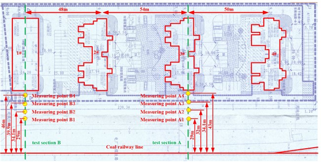
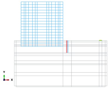
Two test sections perpendicular to the moving direction of the train are set up on the spot near the railway side. Test section A is located on the east side of the 3# building, and Test section B is located on the east side of the 1# building. In each section, four measuring points are located, and the time history data of the vertical acceleration is collected at each measuring point. A sketch map of the test sections and measuring points is shown in Fig. 1 and the detailed information about the location of each measuring point is listed in Table 2.
Fig. 1Diagram of the test sections
2.2. Evaluation criterion
According to the existing “Urban regional environmental vibration standards” (GB10070-88) for railway, the weighted vibration acceleration level as a function of time in the vertical direction (i.e. in the following section) in the residential area and the cultural and educational area should not be higher than 70 dB and 67 dB during the day and at night, respectively; in the region 30 m and larger away from the central line of the outer track, the should not be higher than 80 dB. Therefore, field measurement is conducted at sensitive locations within 0.5 m away from the outer wall of buildings in an adjacent residential area and at a site 30 m away from the central line of the outer track.
Table 2Arrangement of measuring points
Test section | Measuring point | Distance away from the track central line/m | Measured item |
A | Point A1 | 29 | Environmental vibration adjacent to the railway |
Point A2 | 32 | Environmental vibration before the slope protection piles | |
Point A3 | 34.1 | Environmental vibration before the slope protection piles | |
Point A4 | 43 | Environmental vibration outside residential buildings | |
B | Point B1 | 9 | Environmental vibration adjacent to the railway |
Point B2 | 34.1 | Environmental vibration before the slope protection piles | |
Point B3 | 39.9 | Environmental vibration before the slope protection piles | |
Point B4 | 46 | Environmental vibration outside residential buildings |
2.3. Test results and discussions
In this section, the data collected when a fully loaded freight train is passing by is taken as the typical data for analyzing the characteristics of the induced soil vibration. The time history and frequency analysis of the recorded data are carried out.
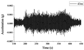
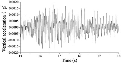
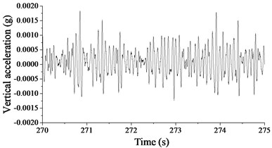
Fig. 2 and 3 show the time histories of the acceleration signals recorded at the measuring points in Section A and B, respectively. The plots demonstrate small difference between the acceleration signals collected at different measuring points in Section A and B. The maximum acceleration is not more than 0.002 g, and the amplitude of acceleration decreases more significantly when the vibration is transmitted to Measuring point A4 or B4.
Fig. 2Acceleration signals recorded in test section A
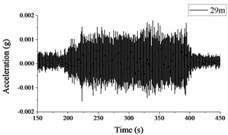
a) Measuring point A1
b) Measuring point A4
Fig. 3Acceleration signals recorded in test section B
a) Measuring point B1
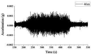
b) Measuring point B4
Fig. 4 and 5 show the time history curves of the weighed vibration acceleration level as a function of time in the vertical direction () at different measuring points in the two test sections, and is expressed as:
where is the reference acceleration, defined to be 10-6 m/s2, and is the running r.m.s. of the weighted acceleration, which is expressed as:
The plots indicate that when the freight train is passing by, the is distributed in the range of 50-77 dB in Section A, and in the range of 45-74 dB in Section B; moreover, with the increase of distance between the measuring point and the railway, the maximum values of on both test sections gradually decrease. In Section A, at the measuring points 29 m and 43 m away from the central line of the railway, the maximum values of are 77 dB and 75 dB, respectively. In Section B, the maximum values of are 74 dB and 71 dB at the measuring points 29 m and 46 m away from the central line of the railway, respectively.
Table 3 lists the calculated maximum based on the data recorded at all measuring points in Section B. In the region adjacent to the railway, the is lower than 80 dB during the day and at night, so the requirement in the standard is satisfied. However, in the region 0.5 m away from the outer wall of buildings in the residential area, the is in the range of 58-74 dB, which is 0-4 dB higher than the specified limit during the day and 0-2 dB higher than the specified limit at night. Hence the environmental vibration in the residential area cannot meet the requirement in the standard, and vibration isolation measures must be adopted.
Fig. 4The measured VLz at each test point located in section A
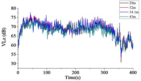
Fig. 5The measured VLz at each test point located in section B
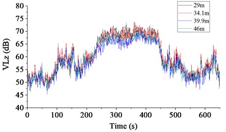
Table 3The VLz measured in test section B
Measuring point | Time | (dB) | Vibration level above the requirement (dB) |
B1 | Daytime | 69.91 | Satisfactory |
B4 | Daytime | 71.97 | 1.97 |
B1 | Daytime | 76.13 | Satisfactory |
B4 | Daytime | 73.76 | 3.76 |
B1 | Night | 68.37 | Satisfactory |
B4 | Night | 57.60 | Satisfactory |
B1 | Night | 69.31 | Satisfactory |
B4 | Night | 68.94 | 1.94 |
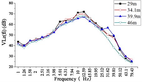
In order to further analyze the spectral characteristics of the environmental vibration induced by freight train, the 1/3-octave spectra of at the four measuring points in each test section when the train is passing by are presented in Fig. 6 and 7. is defined as the weighted vibration acceleration level as a function of the central frequency in the vertical direction, and is expressed as:
where is the reference acceleration, defined to be 10-6 m/s2, and is the weighted acceleration level as a function of the central frequencies in the one-third octave bands. It can be known that for Section A, the fundamental frequency is between 4-12Hz and the vibration level is distributed in the range of 65-75 dB; for Section B, the fundamental frequency is between 8-15 Hz, and the vibration level is distributed in 65-75 dB. At all the four measuring points in the same test section, the fundamental frequencies are very close, and at all the measuring points in both sections, the vibration level declines significantly at frequencies above 20 Hz.
Fig. 6The 1/3-octave spectrum of the measured VLzfi at each test point located in section A
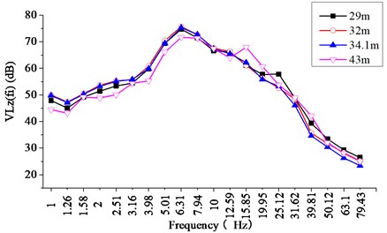
Fig. 7The 1/3-octave spectrum of the measured VLzfi at each test point located in section B
3. Theoretical model
In order to examine the vibration isolation effect of different arrangements of piles in row, a “vehicle-track” model and a finite-element “railway-stratum-building” model is constructed. The fastener force derived with the vehicle-track model is taken as the excitation source and applied to the railway-stratum-building model, and then the vibration acceleration response of the soil is obtained for different arrangements of vibration isolation piles. By analyzing the calculated results, the final arrangement of vibration isolation piles is determined, which meets the requirements of vibration control in the planned building area.
3.1. The dynamic model of the vehicle and track
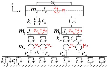
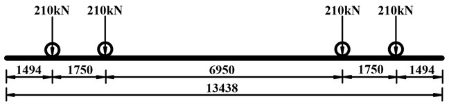
In order to accurately simulate the contact force between the vehicle wheel type and track (force of fastener), the C64 freight wagon commonly used in practice is considered as the vehicle in the model, and the diagram of the axle loads is shown in Fig. 9. According to the actual situation, the vehicle model has reasonably simplified structure and assumptions are made to ensure the validity of simulation results to the maximum extent.
3.1.1. Vehicle model
A simplified model of the vehicle is shown in Fig. 8. Considering the nodding and up-down movements of the vehicle body and bogie, the model has a total of six degrees of freedom, and the equations of motion for each component of the vehicle are listed in Eqs. (4)-(13).
Fig. 8The vehicle model
Up-down movement of car body:
Nodding motion of car body:
where is the vertical displacement of car body; is the rotational displacement of car body; and are the vertical displacement of the front bogie and rear bogie, respectively; is the mass of the car body; is the moment of inertia of the car body; and are the spring stiffness and damping coefficient of the second suspension system; is half of the longitudinal distance between the centers of gravity of the front bogie and the rear bogie.
Up-down movement of front bogie:
Nodding motion of front bogie:
Up-down movement of rear bogie:
Nodding motion of rear bogie:
where and are the rotational displacements of the front bogie and rear bogie, respectively; , , and are the vertical displacements of the four wheel sets; is the mass of bogie frame ; is the moment of inertia of the bogie frame; and are the spring stiffness and damping coefficient of the primary suspension system, respectively.
Up-down movement of the 1st wheelset:
Up-down movement of the 2nd wheelset:
Up-down movement of the 3rd wheelset:
Up-down movement of the 4th wheelset:
where , , , and are the vertical displacements of the four wheel sets; is the mass of the wheelset;
The vehicle is considered in accordance with the C64 freight train, and the layout of the train load is shown in Fig. 9.
Fig. 9Diagram of the axle loads of the C64 freight wagon
3.1.2. Track model
The model of the track is obtained using the finite element method, and it is written as:
where:
where denotes the number of elements; and are the Rayleigh damping coefficients; is number of wheelset.
is the displacement vector of the th element node, and can be written as:
where and are the vertical deflections of the (2)th and (2+2)th element node, respectively; ,are the rotational angle of the (2)thand (2+2)thelement node, respectively.
is the mass matrix of rail element, and may be expressed as:
where is the element length, and is the mass per unit length of rail.
is the stiffness matrix of rail element, and can be written as:
where is the bending stiffness of the rail, and is the bending moment of inertia of the rail.
is the stiffness matrix of the support element, and can be written as:
where is the stiffness coefficient of the fastener.
is the vector of loads acting on the rail, and can be written as:
where is the force between wheel and rail, and is the Hermitian cubic interpolation function.
Since each wheel is assumed to be always in contact with the rail beam, the force between rail and wheel can be expressed as:
When “ 1, 2”, 1; when “ 3, 4”, 2.
The vertical displacements of the wheel sets are calculated by the vertical deflections of rail and rail irregularities , and can be expressed as:
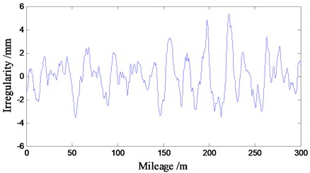
In this paper, the trigonometric series method is used to simulate the power spectrum density function in the presence of track irregularity on the Shuohuang Railway in China, and the time-domain sample of track irregularity is shown in Fig. 10.
Fig. 10Track irregularity
In order to save the computing time, a group of three wagons is considered, running at the speed of 13.6 km/h. The step size of integration is 0.05 s, and the cut-off frequency is 100 Hz in the computation, meeting the requirements in calculating the response of ground surface velocity. The force acting on the fastener is calculated by:
The calculated time history of the force acting on the fastener is shown in Fig. 11.
3.2. The finite-element model of the track-stratum-building system
3.2.1. Structure description
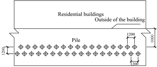
This paper focuses on the residential buildings which are close to the existing medium to low-speed freight railway lines, and vibration attenuation measures cannot be applied to them nor the vibration source because of the limitations imposed by the site conditions. The feasibility of modifying the slope protection piles outside the building to make them function as vibration isolating piles is explored in this study. Such modification on the slope protection piles makes them not only play the role of building foundation pit protection but also have vibration isolation effect.
The research in this paper is based on the actual engineering background, and the specific project is shown in Fig. 12. Outside the building, a row of slope protection piles have already been set up to ensure the stability of foundation pit excavation. According to the requirements of building construction, the diameter of each pile is 600 mm, and the spacing between piles is 1200 mm. For this project, we proposed a double row pile vibration isolation scheme by adding another row of similar piles on the outside of the existing pile row.
Fig. 11The derived force of fastener
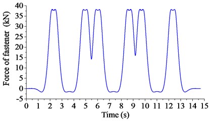
Fig. 12The arrangement of double row vibration isolation piles
3.2.2. Track model
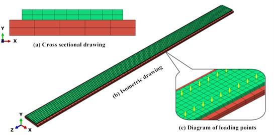
In order to accurately simulate the environmental vibration induced by the freight train, a model of non-ballasted slab track is constructed using the C3D8R solid elements in the finite element analysis software ABAQUS. The sizes and the material properties of the track slab and base plate are shown in Table 4 and 5, respectively. The structure of the track is shown in Fig. 12.
Table 4Size of the track
Parts | Length (mm) | Height (mm) | Width (mm) |
Track slab | 46000 | 200 | 2400 |
Base plate | 46000 | 300 | 3000 |
Table 5Track material properties
Parts | Elastic modulus (N/m2) | Poisson ratio | Density (kg/m3) |
Track slab | 3.60e10 | 0.167 | 2500 |
Base plate | 3.25e10 | 0.167 | 2500 |
3.2.3. Building model
The building model takes the 2# and 3# residential building in the Shangchenghuadu residential area as the prototype; the ground part has 14 stories and the underground part has 2 stories, with a total of 16 stories. The finite element model is constructed with the S4 shell element in ABAQUS, and the element thickness is 0.3 m, as shown in Fig. 13.
Fig. 13The track model
3.2.4. Stratum-pile model
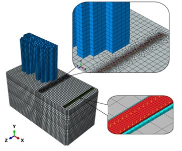
A stratum model is constructed under three conditions: with no piles, with a single row of piles and with double rows of piles, to analyze the vibration isolation effect of different schemes of pile arrangement (the details are shown in Table 6). According to the shear wave velocity of the soil stratum and the size requirement in a dynamic finite element model, the size of the stratum model is determined to be “100 m×50 m×50 m”, In addition, the soil strain induced by rail transport is generally less than 10-5, and at this point the soil is in the elastic state [14], so the soil is assumed to be linear elastic constitutive in this model. The soil model is divided into 11 layers according to the survey result on site.
The dynamic parameters of each layer are shown in Table 1. The piles and soil stratum are simulated with the C3D8R solid elements, and the surface binding relationship is defined between the piles and soil, so relative sliding is not allowed to occur and the actual force applied to the piles can be simulated. In order to prevent the reflection of waves on the manually defined stratum boundaries, a layer of soil mass extending in five infinite directions is defined to simulate an infinitely large stratum, which is constituted by the CIN3D8 infinite elements. Based on the definitions mentioned above, the case with piles in double rows is shown in Fig. 14, as an example of the constructed track-stratum-building model.
Fig. 14The overall stratum-pile model
a) Whole model
b) Cross section wireframe
Table 6Parameters of row piles
Computed cases | No. of rows | Pile diameter (mm) | Inter-pile spacing (mm) |
1 | 0 | – | – |
2 | 1 | 600 | 1200 |
3 | 2 | 600 | 1200 |
3.3. Model validation
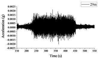
The model is validated based on the test data in Section A. Fig. 15(a) and (b) show the simulated and measured acceleration signal of soil mass vibration, respectively, and the measured and simulated maximum at locations with different distances away from the railway are listed in Table 7. The elastic modulus of the surface soil in the finite element model is adjusted by comparing the time history of the acceleration calculated with the model to that of the measured acceleration. The figures show that the simulated and measured amplitudes of the acceleration signals of soil mass vibration are consistent on the order of magnitude, and both have the maximum acceleration not more than 0.0015 g. The table shows that when the train is passing by, the simulated and measured maximum are both around 75 dB. Therefore, the measured and simulated results are generally in good agreement, and the finite element model constructed in this paper is validated.
Fig. 15Vertical acceleration of the soil mass 28.8 m away from the track central line
a) Simulated result
b) Measured result
Table 7The simulated and measured maximum VLz
Measuring point | Measured result (dB) | Simulated result (dB) |
A1 | 74.8 | 73.1 |
A2 | 75.2 | 73.7 |
A3 | 74.8 | 74.3 |
A4 | 74.2 | 72.1 |
4. Vibration isolation effect of piles in row
Based on the finite element model constructed above, the environmental vibration induced by the freight train running at 13.6 km/h is simulated for different pile arrangements, and the time history of acceleration at the key positions is obtained. Then the vibration isolation effects of different pile arrangements are analyzed.
Fig. 16 shows the vibration isolation effect of different pile arrangements. It can be known that in the absence of piles, the propagation of ground vibration caused by the running freight wagon is only blocked by the building. After the piles are set up, it can be clearly seen that the transmission of ground vibration is blocked by the piles. In addition, the effects of different pile arrangements on vibration isolation can be directly seen, i.e. the more number of rows are the piles placed in, the better the vibration isolation effect is.
The vibration isolation effects of different pile arrangements are further demonstrated by the vibration of soil mass in front of and behind the piles. Fig.17 and 18 show the time history of acceleration before and after different pile setups, respectively. It is shown that the piles have significant vibration isolation effect in front of and behind the piles. The piles in double rows reduces the soil mass vibration acceleration in front of piles by 55 % compared with the piles in a single row, and the soil vibration acceleration in front of a single row of piles is decreased by 33 % compared with that in the absence of piles. Behind the piles in double rows, the soil mass vibration acceleration is reduced by 25 % compared with that behind the piles in a single row, and the soil vibration acceleration behind a single row of piles is decreased by 30 % compared with that in the absence of piles. In general, for both pile arrangements, the levels of vibration acceleration behind piles are all lower than those in front of piles, according with the law of vibration attenuation. Moreover, the double-rows setup has better effects of soil vibration reduction than the single-row setup.
Fig. 16Colored maps displaying the vibration isolation effects of different arrangements of piles
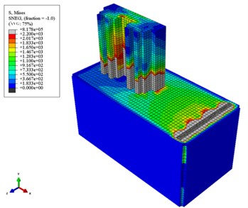
a) With no piles
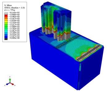
b) With piles in one row
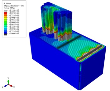
c) With piles in two rows
Regarding the spectral characteristics of vibration, Fig. 19 and 20 show the 1/3-octave spectra of the weighted vibration acceleration level as a function of time central frequency in the vertical direction () in front of and behind different pile arrangements, respectively, when the freight train is passing by. For different pile arrangements, the fundamental frequency of ground vibration in front of and behind piles is in the range of 4-25 Hz, and the is distributed in 55-70 dB. Compared with the case without piles, 0-5 dB reduction of the is achieved in front of the piles in a single row, and 0-9dB reduction is achieved in front of the piles in double rows. In the low-frequency range (below 10 Hz), compared with the case without piles, 2-4 dB reduction of the is achieved behind the piles in a single row, and 2-10 dB reduction in the low-frequency range is achieved behind the piles in double rows. Therefore, with the increase of the number of pile rows, the shows a decreasing trend. It can be seen that vibration isolation piles can reduce the to some extent both in front of and behind the piles.
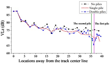
In order to analyze the attenuation of the maximum vibration level in the direction with distance, the weighed vibration acceleration level as a function of time in the vertical direction () at different locations away from the track center line are shown in Fig. 21, for different arrangements of piles. Compared with the case without piles, the can be reduced by 2-4 dB with the single-row setup, and can be reduced by 4-10 dB with the double-row setup.
Field test results show that within 0.5 m outside a building in the residential area, the is 0-4 dB higher than the specified limit during the day and 0-2 dB higher than the limit at night. Hence, the isolation scheme using double-row piles can satisfy the specified limits.
Fig. 17The time histories of the acceleration signals in front of piles
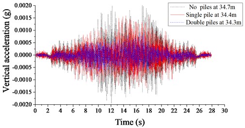
Fig. 18The time histories of the acceleration signals behind piles
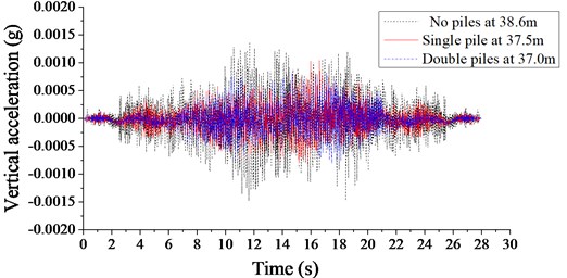
Fig. 19The 1/3-octave spectra of the VLzfi in front of piles
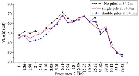
Fig. 20The 1/3-octave spectra of the VLzfi behind piles
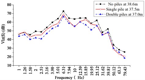
Fig. 21Variation of VLz with the distance from the track central line
5. Conclusions
The test result of environmental vibration induced by a medium- to low- speed running freight train shows that in the region adjacent to the railway, the weighed vibration acceleration level as a function of time in the vertical direction () is lower than 80 dB, which meets the requirements of the “Urban regional environmental vibration standards” (GB10070-88) for railway; however, in the surrounding residential area, the is in the range of 58-74 dB, which is 0-4 dB higher than the specified limit during the day and 0-2 dB higher than the specified limit at night.
For the isolation of environmental vibration induced by this medium- to low- speed running freight train, the vibration isolation effect of building slope pit protection piles is simulated by constructing a “vehicle-track” model and a finite-element model of the railway, stratum and building, and the result shows that the double-row setup of piles can attenuate the environmental vibration in the residential area to levels satisfying the same standard: the can be reduced by 4-10 dB within 5 m behind the piles in double rows. Hence the double-row setup is recommended for the isolation of environmental vibration induced by medium- to low- speed freight rail transport under similar conditions.
The simulated results demonstrate the vibration isolation effects of different pile rows. The piles in double rows reduces the soil mass vibration acceleration in front of piles by 55 % compared with the piles in a single row, and the soil vibration acceleration in front of a single row of piles is decreased by 33 % compared with that in the absence of piles. Behind the piles in double rows, the soil mass vibration acceleration is reduced by 25 % compared with that behind the piles in a single row, and the soil vibration acceleration behind a single row of piles is decreased by 30 % compared with that in the absence of piles.
Compared with the case without piles, 0-5 dB reduction of the is achieved in front of the piles in a single row, and 0-9 dB reduction is achieved in front of the piles in double rows. In the low-frequency range (below 10 Hz), compared with the case without piles, 2-4 dB reduction of the is achieved behind the piles in a single row, and 2-10 dB reduction in the low-frequency range is achieved behind the piles in double rows.
References
-
Sharp C., Woodcock J., Sica G., et al. Exposure-response relationships for annoyance due to freight and passenger railway vibration exposure in residential environments. The Journal of the Acoustical Society of America, Vol. 135, Issue 1, 2014, p. 205-212.
-
Kirzhner F., Rosenhouse G., Zimmels Y. Attenuation of noise and vibration caused by underground trains, using soil replacement. Tunnelling and Underground Space Technology, Vol. 21, Issue 5, 2006, p. 561-567.
-
Zhang Henian, Sun Guangjun, Xiao Junhua, Li Xiongwei Simulation and prediction for environment vibration induced by urban rail transit with elevated line. Rock and Soil Mechanics, Vol. 34, Issue 2, 2013, p. 433-438.
-
Ma Meng, Liu Weining, Jin Hao, Sun Xiaojing Prediction method of the vibration influence on buildings induced by rail transit. China Railway Science, Vol. 32, Issue 2, 2011, p. 27-32.
-
Ma M., Liu W. N., Qian C. Y., et al. Train-induced vibration impact on a historic Bell Tower above two spatial overlapping metro lines. Soil Dynamics and Earthquake Engineering, Vol. 81, 2016, p. 58-74.
-
Wei Pengbo, Xia He, Chen Jianguo, Yao Jinbao, Xia Chaoyi Theoretical and Experimental Study on environmental vibrations induced by trains on viaduct. Engineering Mechanics, Vol. 26, Issue 10, 2009, p. 117-122.
-
Jones C. Low Frequency Ground Vibration//Thompson D. Railway Noise and Vibration: Mechanisms, Modelling and Means. Elsevier Science, Amsterdam, 2009.
-
Ahmad S., Al Hussaini T.-M. Simplified design for vibration screening by open and in-filled trenches. Proceedings of ASCE, Journal of Geotechnical Engineering, Vol. 117, Issue 1, 1991, p. 67-88.
-
Yang Y. B., Hung H. H. A parametric study of wave barriers for reduction of train-induced vibrations. International Journal of Numerical Methods in Engineering, Vol. 40, Issue 20, 1997, p. 3729-3747.
-
Adam M., von Estorf O. Reduction of train-induced building vibrations by using open and filled trenches. Computers and Structures, Vol. 83, Issue 1, 2005, p. 11-24.
-
Jones C. J. C., Thompson D. J., Petyt M. A model for ground vibration from railway tunnels. Proceeding of the Institute of Civil Engineers, Transport, Vol. 153, Issue 2, 2002, p. 121-129.
-
Segol G., Lee P. C. Y., Abel J. F. Amplitude reduction of surface wave by trenches. Journal of the Engineering Mechanics Division, Proceedings of the ASCE, Vol. 104, Issue 3, 1978, p. 621-641.
-
Beskos D. E., Dasgupta B., Vardoulakis I. G. Vibration isolation using open or filled trenches. Computational Mechanics, Vol. 1, Issue 1, 1986, p. 43-63.
-
Dasgupta B., Beskos D. E., Vardoulakis I. G. Vibration isolation using open or filled trenches. Part II: 3-D homogeneous soil. Computational Mechanics, Vol. 6, 1990, p. 129-142.
-
Karlström A., Boström A. Efficiency of trenches along railways for trains moving at sub- or supersonic speeds. Soil Dynamics and Earthquake Engineering, Vol. 27, 2007, p. 625-641.
-
Coulier P., Degrande G., Dijckmans A., et al. Scope of the Parametric Study on Mitigation Measures on the Transmission Path. RIVAS Deliverable 4.1, 2011.
-
With C., Bahrekazemi M., Bodare A. Wava barrier of lime-cement columns against train-induced ground-borne vibrations. Soil Dynamics and Earthquake Engineering, Vol. 29, 2009, p. 1027-1033.
-
Degrande G., De Roeck G. Effectiviteit Van Een Trillingsisolerend Scherm in Het Station Van Het Leopoldkwartier Te Brussel. Leuven, 1992.
-
Lu J. F., Xu B., Wang J. H. Numerical analysis of isolation of the vibration due to moving loads using pile rows. Journal of Sound and Vibration, Vol. 319, Issue 3, 2009, p. 940-962.
-
Ekanayake S. D., Liyanapathirana D. S., Leo C. J. Attenuation of ground vibrations using in-filled wave barriers. Soil Dynamics and Earthquake Engineering, Vol. 67, 2014, p. 290-300.
-
Vanstraelen M. Trench Isolation: Modelling and Measurements Cfr. the Test Bench, CargoVibes Deliverable 3.3. CDM, 2012.
-
Dijckmans A., Ekblad A., Smeka L. A., et al. Efficacy of a sheet pile wall as a wave barrier for railway induced ground vibration. Soil Dynamics and Earthquake Engineering, Vol. 84, 2016, p. 55-69.
-
Coulier P., Cuéllar V., Degrande G., et al. Experimental and numerical evaluation of the effectiveness of a stiff wave barrier in the soil. Soil Dynamics and Earthquake Engineering, Vol. 77, 2015, p. 238-253.
-
Takemiya H. Field vibration mitigation by honeycomb WIB for pile foundations of a high-speed train viaduct. Soil Dynamics and Earthquake Engineering, Vol. 24, Issue 1, 2004, p. 69-87.
-
Dijckmans A., Coulier P., Jiang J., et al. Mitigation of railway induced ground vibration by heavy masses next to the track. Soil Dynamics and Earthquake Engineering, Vol. 75, 2015, p. 158-170.
-
Thompson D. J., Jiang J., Toward M. G. R., et al. Mitigation of railway-induced vibration by using subgrade stiffening. Soil Dynamics and Earthquake Engineering, Vol. 79, 2015, p. 89-103.
Cited by
About this article

