Abstract
In order to study the effect of abrasive flow on the polishing quality of the elbow parts, 90° elbow is used as the research object. The dynamic pressure and wall shear force of different incident angle flow is numerically simulated by setting the process parameters of elbow polishing, which shows that the properly increase entrance angle can improve the uniformity and reliability of abrasive flow polishing, and then, the numerical simulation analysis of turbulence viscosity and wall shear force for different incident pressures are also simulated. It indicates that the properly enhance inlet pressure is helpful to improve the polishing effect and polishing uniformity. Finally, the abrasive grain polishing test is carried out. After the measurement by Mahr stylus measuring instrument, the surface roughness decreases from 1.968 μm to 0.212 μm, which confirm the effectiveness of abrasive flow processing. The roughness value of the inside at the bend after the polishing of the abrasive grain is 0.274 μm by the measurement of the NT1100 Grating Surface Roughness Meter under the pressure condition of 7 MPa. By comparing the polishing effect of the pipe at different pressure and inflow angle, it is found that increase the pressure and inlet angle can improve the polishing effect of the abrasive flow on the curved pipe, but at the same time the uniformity of the polishing is decreased, in other words, the roughness gap at different positions of the elbow will increase. Therefore, it is exceedingly necessary to make some adjustments when in the actual operation.
1. Introduction
There are wide range of applications in industry and life for elbow, such as medical equipment, food, aerospace, ships and other fields. The surface quality of elbow parts tends to need a higher accuracy because of the particularity of use, the lower the surface roughness, the higher the value of use [1-4]. And for the specificity of the inner surface structure of the elbow parts, it is difficult for the traditional polishing method to finish the finishing of the inner surface of the elbow. To this end, abrasive flow technology come into being. The processing technology of abrasive grains has increasingly appeared for the micro-cutting parts, which can realize surface polishing, deburring, round and so on. Therefore, the research for abrasive grain polishing technology has a very important engineering application value and academic significance for the performance improvement of the elbow parts [5-8].
Abrasive grain polishing technology is a new polishing process, whose principle is that the surface of the workpiece is frequently crashed by solid particles suspended in the liquid particles to achieve polishing effect [9-11]. Innumerable abrasive grains are equivalent to the traditional processing tool, which act on the surface of the workpiece, a certain number of cycles (processing time) are usually set due to different components, different parts and different processing accuracy requirements in order to realize polishing, deburring and other demands [12-14].
Aiming at the problem that the inner surface of micro-size and large-curvature curved pipe is difficult to be used for contact finishing, a method using a soft abrasive grain was proposed by Shen Ming. To verify the correctness of the theoretical analysis, the RNG - turbulence model is used to simulate the whole runner in the process. And the experimental platform is built for processing experiments to test the reliability of the simulation results [15]. Gao Hang came up with a mean applying abrasive grain polishing technology directing to the screw parts used manual polishing, and has a poor polishing effect, low efficiency, quality cannot be guaranteed. As a result, a screw jig with helical drainage was designed to eliminate the reflow phenomenon. The helical surface after machining of abrasive flow was reduced from 10.5 μm to 0.45 μm under the experimental conditions [16].
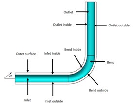
In order to more accurately analyze the flow distribution of the abrasive grains at different locations of the elbows, the elbows are divided into different areas as shown in Fig. 1.
Fig. 1The division of the elbow
2. Analysis on polishing parameters to polishing effect of abrasive grain flow
2.1. Influence of inflow angle on polishing characteristics of abrasive grain flow
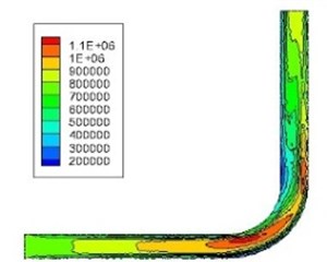
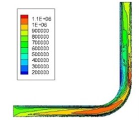
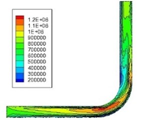
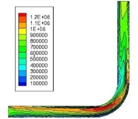
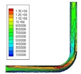
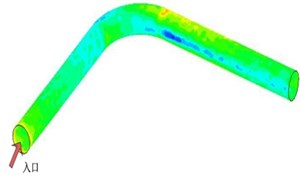
Changing the inlet angle of the abrasive flow causes the change of the angle of collision between the abrasive flow and the wall surface, which in turn leads to a change in the flow state of the abrasive grains. Therefore, the influences that different abrasive grain inflow angles to flow pattern of the abrasive flow in the curved pipe are mainly studied, and the effect of the inflow angle on the polishing of the abrasive flow is analyzed. To examine the effect of different inflow angle to the polishing effect of abrasive grain flow, the abrasive flow conditions at different inflow angles are calculated when the inflow angle is –15°, –10°, –5°, 5°, 10° and 15°, and which is compared with the vertical inflow. After comparison, the numerical analysis can be obtained under different inflow angles and the dynamic pressure distribution is shown in Fig. 2.
By comparing and analyzing the distribution of dynamic pressure at different inflow angles, it can be found from Fig. 2 that pressure distribution of the abrasive grain flow obviously changes with the inflow angle changing. The dynamic pressure of the outside wall surface is larger than the inside over the entire area of the pipe when the inflow angle is in negative condition. As a result, the uniformity of abrasive grain polishing is far from being guaranteed once the negative inflow angle is applied. When the inflow angle is 5°, the dynamic pressure of the inside wall is slightly larger than outside at inlet, while the inflow angle is 10° and 15°, the pressure difference at both sides of the bend and the outlet decreases, but the dynamic pressure at inside is also greater than at outside in inlet. So, the uniformity of abrasive grain polishing can be improved by appropriately increasing inflow angle.
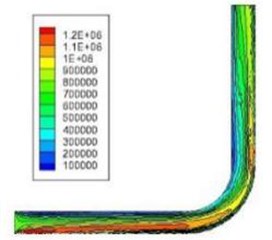
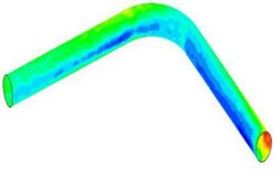
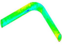
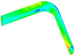
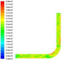
As shown in Fig. 3, it can be detected from the distribution of the shear wall from the 90° bend at different inflow angles that there is a regional decrease at the inlet, while the whirlpool will be produced by abrasive flow due to the structure of pipe at the bend part. Consequently, the wall shear force on the inside of the first half of the curved section is more than the outside. The wall shear force at the inside is greater than the outside at the rear half of the bend section and the outlet affected by the flow state and centrifugal force. When the inflow angle is 5°, the shear force of the wall is decreased rapidly on the outside comparing with the inside at the inlet. However, the distribution of the shearing force is better than that is 0° at the outlet and the bend. When the inflow angle continues to rise, the difference between the wall shear force on both sides of the inlet and the bend is obviously increased, which is no longer beneficial to the uniformity of the abrasive grain polishing.
Fig. 2Dynamic pressure diagram at different inflow angles
a) 0°
b) –15°
c) –10°
d) –5
e) 5°
f) 10°
g) 15°
From the analysis, it can be known that there is a poor polishing uniformity when the inflow angle is negative. On the contrary, it will be better when the inflow angle is positive. As a consequence, the polishing performance can be vastly enhanced by properly elevating inflow angle.
Fig. 3Distribution of wall shear force at different incident angle

a) 0°

b) –15°
c) –10°
d) –5°

e) 5°
f) 10°
g) 15°
2.2. Influence of inlet pressure on polishing characteristics of abrasive grain flow
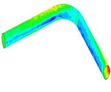
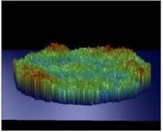
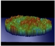
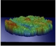
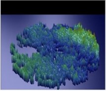
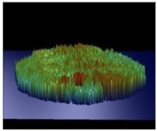
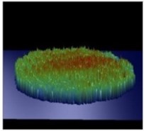
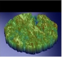
During the polishing process, the turbulence viscosity is an important index of the polishing effect. The distribution of the abrasive grains in the pipe will be affected by the size of the turbulent viscosity, which in turn will affect the flow state of the abrasive grains. Therefore, the polishing effect of the abrasive grains finally will be influenced. There are many factors that affecting the turbulence viscosity. And in this section, the different inlet pressure to the effect of abrasive flow polishing will be mainly examined. Different inlet pressures can produce turbulent viscosity of different sizes, thus the polishing effect on the pipe will be influenced.
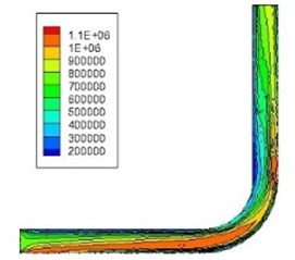
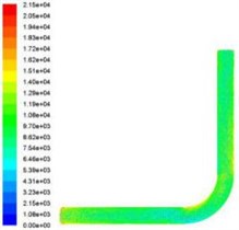
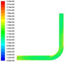
In this part, 3 MPa, 5 MPa and 7 MPa are selected as polishing parameters. The turbulence viscosity distribution of 90° elbow is calculated by numerical simulation under three different inlet pressure conditions as shown in Fig. 4.
In the turbulence viscosity distribution at different inlet pressure shown in Fig. 4, which can be seen that the turbulent viscosity of the abrasive flow in the pipe is also increased with the polishing pressure increasing. and the turbulent viscosity near the wall is larger than that of the pipeline center, which because there exist grinding between the abrasive flow and the workpiece, eventually resulting in a greater turbulence viscosity. It can be obtained from the analysis that increasing the inlet pressure is equivalent to increasing the turbulent viscosity of the abrasive flow, and the turbulence degree of the abrasive flow in the pipe becomes larger, so that the irregular movement of the abrasive grains inside the pipe is more intense. The more frequent impact on the wall of the pipe, the better the polishing effect. Under the same initial conditions, the shear forces of the wall during the grinding process are analyzed, and the distribution for wall shear force under different inlet pressure are shown in Fig. 5.
Fig. 4Turbulent viscosity distribution at different inlet pressure
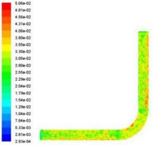
a) 3 MPa
b) 5 MPa
c)7 MPa
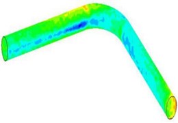
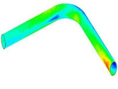
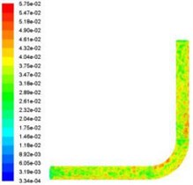
Fig. 5Wall shear force at different entrance pressure

a) 3 MPa
b) 5 MPa
c) 7 MPa
It can be inferred that the wall shear force gradually increases with the increase of the inlet pressure, and it is most likely to be reflected at the bend by comparing the wall shear forces at different inlet pressures. Because in the bend, the speed and wall shear force is also growing with the pressure increasing. There is a violent crash in the bend, turbulence effect is more apparent, more frequent collisions between particles will be appeared, the more violent movement of disorder, the better the grinding effect on the wall. While at the outlet, the wall shear force is relatively small, which due to the collisions between abrasive flow and pipe, leading to the loss of part of the kinetic energy, resulting in reduced speed, wall shear force is also weakened. Consequently, the polishing effect is poor and the uniformity is not good. So, it would be better that regarding the outlet as inlet and polish it again in the polishing process.
3. Experimental analysis of polishing quality of bend by abrasive flow
Due to Stainless steel has favorable corrosion resistance and heat resistance, widely used in food production equipment, medical equipment, auto parts, chemical equipment and other fields. Therefore, the stainless steel tube whose outside diameter and inside were 10 mm and 8 mm respectively was chose as the experimental object of abrasive grain polishing. The elbow part to be polished was shown in Fig. 6.
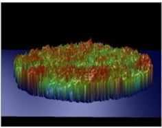
The silicon carbide particle whose size was 8 μm was selected as the abrasive particles. The main components of the grinding fluid carrier were hydraulic oil and a small amount of triethanolamine. And the final abrasive sample concentration was 20 %. The pipe after cutting needed to be cleaned for accurately measuring the surface quality after processing. There were several steps: put the workpiece into the 2000 Hz ultrasonic oscillator, and a little zinc oxide and alcohol were needed, which assured that the removal of stains on the surface of the workpiece. At the same time, that anti-oxidation measures could also be formed. And after that, the elbow was put into the hot box and dried of water so that reach detection standards, then the related testing could be carried out. The workpiece after cutting was observed under an electron microscope, and the image of elbow before and after polishing was shown in the Fig. 7.
Fig. 6The elbow to be polished
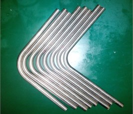
Fig. 7The workpiece before and after polishing
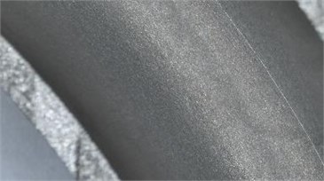
a) Before polishing
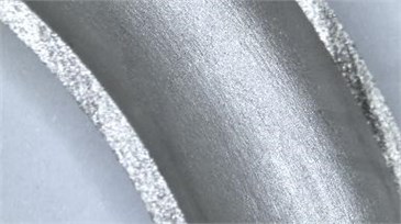
b) After polishing
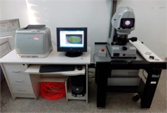
Roughness is an extremely important indicator of the quality of the workpiece surface. In order to analyze the effect of abrasive flow on the elbow polishing, the Mahr stylus measuring instrument and the NT1100 grating surface roughness measuring instrument were used to measure the roughness of the different area before and after the polishing. NT1100 grating surface roughness measuring instrument shown in Fig. 8.
Fig. 8NT1100 grating surface roughness measuring instrument
3.1. Mahr stylus measuring instrument for surface roughness measurement
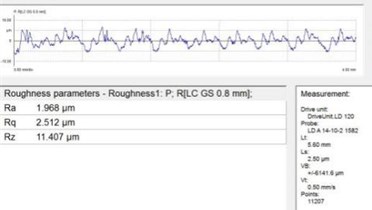
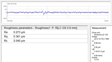
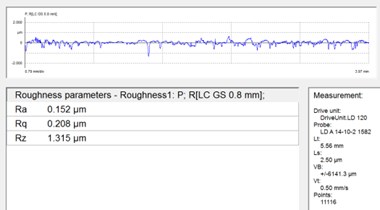
In this experiment, three workpieces were selected to mark the original 1 #, sample 2 #and sample 3 # respectively. After the abrasive flow polishing test was completed, the Mahr stylus measuring instrument was selected to measure surface roughness. And the measurement result was shown in Fig. 9.
As shown in Fig. 9, the result of the original measurement was 1.968 μm before polishing, while after the processing, the test results demonstrate that the amplitude of the fluctuation was small, the average measurement result was 0.212 μm, and the polishing effect was better comparing with before. In consequence, the effectiveness and reliability of the abrasive flow processing were verified.
Fig. 9The measurement result for the surface roughness of the workpiece
a) 1 #
b) 2 #
c) 3 #
3.2. Measurement of surface roughness of NT1100 grating measuring instrument
In this experiment, the pipe was polished for comparison at three different pressures. It can be discovered from the above that there would be a large difference in roughness at the bend and the outlet on both sides of the roughness after abrasive flow polishing. Therefore, the comparison for roughness of the bend and the outlet was chiefly analyzed under different pressure conditions. To save time and keep efficiency, the roughness was tested under only 3 MPa and 7 MPa. The measurement results are shown in the Fig. 10 and Fig. 11.
After finishing the data, draw it as a table, as shown in the Table 1.
Table 1The results of roughness detection under different pressure inlet conditions
Roughness / μm inflow pressure | Bend | Outlet | ||
Inside | Outside | Inside | Outside | |
3 MPa | 0.578 | 0.573 | 0.593 | 0.587 |
5 MPa | 0.452 | 0.447 | 0.458 | 0.451 |
7 MPa | 0.285 | 0.274 | 0.334 | 0.300 |
It can be got from Table 1 that the polishing performance of the abrasive flow on the curved pipe was gradually enhanced with the increase of the inlet pressure. When the inlet pressure is 7 MPa, the roughness value of the inside of the bend of the pipe reaches 0.274 μm, Comparison of the difference in the same area can be found that as the inlet pressure increased, the difference in roughness between the inside and outside of the curved section is changed from 0.005 μm to 0.011 μm. The difference in the roughness of the outlet region is changed from 0.006 μm to 0.034 μm. In a word, it can be seen that the abrasive flow to the polishing performance of the curved pipe boosted with the inlet pressure increasing, but the difference in roughness at the different area of the elbow increased.
Fig. 10Different position roughness at inlet pressure of 3 MPa
a) Inside at bend
b) Outside at bend
c) Inside at outlet
d) Outside at outlet
Fig. 11Different position roughness at inlet pressure of 7 MPa
a) Inside at bend
b) Outside at bend
c) Inside at outlet
d) Outside at outlet
4. Conclusions
In order to study the effect of inflow angle on the polishing characteristics of abrasive grains, the dynamic and wall shear forces at different inflow angles are analyzed. The abrasive flow conditions at different inflow angles are calculated when the inflow angle is –15°, –10°, –5°, 5°, 10° and 15°, and which is compared with the vertical inflow. The results reveal that the uniformity of abrasive grain polishing can be improved by appropriately increasing inflow angle. Through the numerical simulation results for the wall shear force, it is found that the polishing performance is the best when the inflow angle is 0°-5°.
To study the effect of inflow pressure on the polishing characteristics of abrasive grains, three kinds of inlet conditions that 3 MPa, 5 MPa and 7 MPa are used to calculate the turbulence viscosity and wall shear force of 90° elbow. The numerical simulation results manifest that the polishing effect of the abrasive grain flow can be enhanced by properly increasing inlet pressure. However, the uniformity of the polishing is weakened if excessively increase. Therefore, it can be adjusted according to the need during the actual abrasive grain polishing process.
The surface roughness decreases from 1.968 μm to 0.212 μm after the measurement by the Mahr stylus measuring instrument. In addition, the roughness value of inside at the bend after the abrasive flow is reduced from 1.54 μm to 0.274 μm under the pressure of 7 MPa by NT1100 grating measuring instrument. In summary, the polishing performance can be raised by appropriately increase inflow pressure, but the polishing uniformity will decline.
References
-
Han Bing, Liu Lixin, Chen Yan Optimization of process parameters on magnetic abrasive finishing to inner surface of bending pipe. China Mechanical Engineering, Vol. 6, 2015, p. 814-817.
-
Li Xin Bent-Pipe on the Inner Surface Polishing Technology Research. Changchun University of Science and Technology, 2009.
-
Zhang Lingyun, Wu Fenglin Present Situation and Prospect of Abrasive Flow Machining. Mechanical Engineering and Automation, Vol. 17, Issue 5, 2006, p. 166-168.
-
Ji Shiming, Huang Xihuan, Tan Dapeng, et al. Gas-liquid-solid abrasive flow polishing and its process parameter optimization. Optics and Precision Engineering, 2016,24(4):855-864.
-
Li Junye, Qiao Zemin, Yang Zhaojun, et al. Influence of abrasive concentration on the processing quality of abrasive flow in mesoscopic scale. Journal of Jilin University (Engineering and Technology Edition), Vol. 47, Issue 3, 2017, p. 837-843.
-
Ding Jinfu, Liu Runzhi, Zhang Kehua Micro cutting mechanism of abrasive flow precision machining. Optics and Precision Engineering, Vol. 22, Issue 12, 2014, p. 3324-3331.
-
Venkatesh G., Sharma A. K., Kumar P. On ultrasonic assisted abrasive flow finishing of bevel gears. International Journal of Machine Tools and Manufacture, Vol. 89, 2015, p. 29-38.
-
Dong Jiaguang, Zhang Bin, Yi Guohua, et al. Analysis of material removal and surface roughness in abrasive flow machining process. Design and Manufacture of Diesel Engine, Vol. 22, Issue 1, 2016, p. 45-56.
-
Li Junye, Sun Fengyu, Wu Shaoju, et al. An analysis of velocity-temperature characteristics of liquid-solid two-phase abrasive flow machining of non-linear tubes. 5th International Conference on Applied Mechanics and Mechanical Engineering (ICAMME), Vol. 6, 2015, p. 36-39.
-
Li Junye, Hu Jinglei, Zhang Xinming, et al. The design and analysis on fixture for polishing internal gear tooth surface by solid-liquid two phase flow. Manufacturing Automation, Vol. 38, Issue 11, 2016, p. 66-74.
-
Ji Shiming, Tang Bo, Tan Dapeng, et al. Structured surface softness abrasive flow precision finish machining and its abrasive flow dynamic numerical analysis. Journal of Mechanical Engineering, Vol. 46, Issue 15, 2010, p. 178-184.
-
Pan Yan The Technologic Research of Mould Structure Surface Polishing Processing Based on Flexible Liquid-Solid Two Phase. College of Mechanical Engineering Zhejiang University of Technology, 2009.
-
Tan Yuanqiang, Li Yi On the model and pressure simulation of solid-fluid two phase flow for abrasive flow machining. China Mechanical Engineering, Vol. 19, Issue 4, 2008, p. 439-497.
-
Zhao Lvshun, Tu Danhua, Ye Jian et al. Initial study of a theoretical near-wall turbulence model. Journal of Aerospace Power, Vol. 20, Issue 2, 2005, p. 177-181.
-
Shen Ming, Dai Yong, Chu Cong, et al. Soft abrasive flow machining simulation and experiment of the large curvature bend based on RNG k-s model. Hydraulics Pneumatics and Seals, Vol. 5, 2016, p. 39-44.
-
Gao Hang, Fu Youzhi, Wang Xuanping, et al. Simulations and experiments on finishing process of screw surface by using abrasive flow machining. Journal of Zhejiang University (Engineering Science), Vol. 50, Issue 5, 2016, p. 920-926.
Cited by
About this article

The authors would like to thank the National Natural Science Foundation of China No. NSFC 51206011, Jilin Province Science and Technology Development Program of Jilin Province No. 20160101270JC and No. 20170204064GX, Project of Education Department of Jilin Province No. 2016386.
