Abstract
Rolling bearing’s fault mode usually shows compound faults in aero-engine. The compound faults characteristics are more complex than single one, and many signal analysis methods have rather great limitation for compound fault characteristic extraction which leads to the difficulty to monitor the running state of rolling bearing in aero-engine. Based on above analysis, a method of combining wavelet transform with cyclostationary theory, autocorrelation function and Hilbert transform is proposed and applied to extract characteristic frequency of rolling bearing from compound faults mode only according to single-channel vibration acceleration signal of aero-engine. Meanwhile, a consideration is given to the influence of sensor installation position, compound fault types in the extraction of compound faults characteristics. The result indicates that the proposed new method can effectively monitor rolling bearing running state in four different compound fault modes just according to single-channel vibration acceleration signal no matter sensors are installed in horizontal or vertical direction.
1. Introduction
Aero-engine works at high temperature and speed in adverse circumstances, and rolling bearing is one of key parts in aero-engine. A real aero-engine fault mode is usually compound considering that intercoupling between faults, while the more researches are mainly concentrated on single fault rather than compound faults at present [1, 2]. The compound faults characteristic extraction is far more difficult than single fault, with the addition of many signal analysis methods (including Hilbert transform and cyclostationary theory, etc.) is effective for single fault rather than compound faults [2, 3], which leads to the particular difficulty to extract rolling bearing compound faults characteristics based on vibration signal in aero-engine. Therefore, how to effectively monitor running state and extraction compound fault characteristics of rolling bearing according to vibration signal is important.
Closely symmetric physical structure and rotation mode, which determines aero-engine vibration signal, has cyclostationary features and the rolling bearing fault characteristics can be studied in cyclostationary theoretical frame [4]. Cyclostationary theory has been applied to rotating machine fault diagnosis in recent two decades, and some noteworthy conclusions have been obtained with vibration signal of rolling bearing and gears. J. Antoni’s research is the most representative, in 2001, J. Antoni et al. applied cyclostationary theory and envelop analysis to rolling bearing fault diagnosis, considering that the relationship between spectral and envelop analysis for cyclostationary signal [4]. Meanwhile, Antoni J. et al. were dedicated to modeling rotating machine signal as cyclostationary processes; a comprehensive methodology was proposed in order to process actual cyclostationary signals, and three typical applications dealing with vibration signals of IC engine, rolling element bearing and a gearbox were analyzed by different types of cyclostationarity in 2004 [5]. In 2005, Antoni J. combined cyclostationary theory and blind separation algorithm to study convolution mix blind separation algorithm based on cyclostationary theory [6]. Ming Yang, et al., combined envelop spectrum analysis with cyclic Wiener filter to extract rolling bearing weakly faults, and used simulated signal and real bearing accelerated life test to demonstrate effectiveness of the method [7]. P. Borghesani et al., introduced an original analytical derivation of the statistical tests for cyclostationarity in the squared envelope spectrum, and the proposed method was verified by experimental vibration data of rolling element bearing in 2013 [8]. D. Boungou et al., proposed fatigue damage detection method according cyclostationary theory in 2015 [9]. The application of cyclostationary theory to rolling bearing and gear fault diagnosis has been widely promoted by scholar researches home and abroad. While satisfactory result is difficult to obtain probably by cyclic statistics alone because compound faults signal of aero-engine is weaker and more complicated, especially the intercoupling between faults. Wavelet transform is applied in a wide range of applications in the compound faults diagnosis due to its time-frequency localization characteristics [10-12]. Considering that multiresolution analysis of wavelet transform can separate different frequency signal by signal pass corresponding frequency bands [11], and can be used to analyze multiple faults. Therefore, some multiple fault diagnosis methods have been proposed based on wavelet transform in recent year. The combination of spectrum autocorrelation and the wavelet decomposition method was proposed for separating compound faults characteristics of the inner and outer from rolling bearing signal by Ming Anbo et al. in 2013 [13]. Independent component analysis was combined with dual-tree complex wavelet transform to separate the fault feature from compound rolling bearing fault signal by Xu Yonggang et al., and experiment results verified propose method’s effectiveness and feasibility in 2014 [14]. Peng Li et al. proposed a multiscale slope feature extraction method using wavelet-based multiresolution analysis for rotating machinery fault diagnosis in 2013 [15]. Autocorrelation function of signal can reserve the periodic components and eliminate noises at the same time, and meanwhile can change frequency modulated signal to amplitude modulated signal which is usually included in faults signal of rolling bearing. Hilbert transform can obtain the complex envelope of signal which removes regular vibration component. Based on above analysis, this paper proposes a new method combing autocorrelation function, wavelet transform, and Hilbert transform and cyclostationary theory to extract rolling bearing compound faults characteristic of aero-engine based on single-channel vibration acceleration signal.
2. Theory analysis
2.1. Cyclic autocorrelation function
Suppose is a continuous signal and then autocorrelation function of is:
where is statistical average value, is delay factor, and represents conjugate. If is cyclic function of time , then has second-order cyclostationary characteristics. Because is a period function, it can be obtained through Fourier series expansion:
, represents cyclic frequency, and represents period of autocorrelation function, then Fourier transform coefficient is:
represents cyclic autocorrelation function of cyclic frequency equal to .
Suppose is an amplitude modulated signal, then:
where represents carrier frequency, and represents modulation frequency, and is respectively amplification of carrier signal and modulation signal. We also know:
According to Eqs. (3-5), it is inferred:
It is obvious that, cyclic autocorrelation function is not equal to zero if and only if cyclic frequency, , , , and , while represents stationary signal. If one value is taken, and the slice signal of cyclic autocorrelation function is analyzed in this value, then fault characteristics can be extracted by obtaining modulation spectrum of slice signal.
2.2. Wavelet transforms
Suppose is a continuous signal, then wavelet transform is defined as the integral of the raw signal multiplied by scaled, shifted versions of a basic wavelet function :
The scaling function is as below:
Then by the DWT (discrete wavelet transform) the wavelet coefficients of a signal can be defined by the following equations:
2.3. Characteristic frequency of rolling bearing
Every fault type of rolling bearing is related with specific frequency whose characteristics can be used to monitor running state and identify fault types of rolling bearing. Supposing pitch diameter is , rolling elements diameter and number is respectively and , and contact angle is equal to zero, and the rotating speed is , and then inner ring rotation frequency is equal to . In general cases, the relative rotation frequency between inner ring and outer ring of rolling bearing is equal, due to outer ring rotating and inner ring fixed. Thus, the characteristic frequency of rolling bearing can be expressed as follows:
Frequency of rolling element passing by inner ring , namely inner ring characteristics frequency:
Frequency of rolling element passing by outer ring , namely outer ring characteristics frequency:
Rotation frequency of rolling element , namely rolling element characteristics frequency:
Rotating frequency of retainer , namely retainer characteristics frequency:
3. Rolling bearing compound faults experiment
3.1. Aero-engine rotor-rolling bearing experiment rig
Rotor-rolling bearing experiment rig is shown in Fig. 1; it is composed of adjustable-speed motor, rotation shaft, rotor disc, gear case, ball bearing, bearing chock and integrated electronic control system. The rotor shaft is sustained by rolling bearing, and fault bearing type is HRB6304, of which geometric parameters rolling element diameter, pitch diameter, inner ring diameter, outer ring diameter and rolling elements numbers of rolling bearing are respectively 9.6 mm, 36 mm, 20 mm, 52 mm and 7. The rotor-rolling bearing experiment rig can simulate weak and complicated fault involved in inner ring, outer ring, rolling element and retainer of rolling bearing.
3.2. Aero-engine rotor-rolling bearing compound fault experiment
The rolling bearing compound faults occurred in outer ring and inner ring; outer ring and rolling elements; inner ring and rolling elements; inner outer, outer ring and rolling elements, the compound faults of rolling bearing was simulated by aero-engine rotor-rolling bearing experiment rig in this paper. Spark wire cutting method was applied to damage rolling bearing, and cutting measurement was 0.2 mm. Meanwhile, the rolling bearing fault experiments involved in the paper are based on the acceleration signal collected by the acceleration sensors Model 4508 provided by Demark Brüel&Kjær, and the rotating speed was measured by SE series eddy current displacement sensors provided by instrument factory Southeast University. Data collector Model is USB9234 provided by National Instruments. The experiment was conducted under room temperature.
The acceleration sensors were installed in vertical upper, horizontal right and horizontal left of bearing chock. Installation position of acceleration sensors is shown in Fig. 1. Compound faults rolling bearings are shown in Fig. 2. represents rotation frequency, , , and is respectively outer ring characteristic frequency, inner ring characteristic frequency, rolling elements characteristic frequency and retainer characteristic frequency of rolling bearing in this paper. Rolling bearing characteristic frequency calculation is according to Eqs. (12-15).
Fig. 1Aero-engine rotor-rolling bearing experiment rig
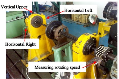
Fig. 2Compound faults of rolling bearing

4. A new characteristic analysis method on rolling bearing based on single-channel vibration acceleration signal
The vibration amplitude will be modulated by characteristic frequency corresponding with fault types of rolling bearing in fault occurrence. Namely, is equal to fault characteristic frequency corresponding with fault types in Eq. (6). Hence, we can make equal to these feature frequencies or its double frequency to monitor and analyze running state of rolling bearing. Satisfying result is difficult to obtain probably by cyclic statistics alone considering that compound faults are rather weaker and more complex than single fault of rolling bearing and wavelet transform is combined with cyclostationary theory. Meanwhile, autocorrelation function and Hilbert envelop spectrum was respectively used to reduce noise and demodulate vibration signal. The concrete research method of this paper is shown in Fig. 3.
Fig. 3Proposed new method in this paper

By comparing proposed new method with the common research methods for extracting rolling bearing characteristic frequency combined cyclic autocorrelation function and Hilbert transform at present, the difference is shown as follows:
A: The autocorrelation function is used to reduce noise and change frequency modulated signal to amplitude modulated signal which is usually included in faults signal of rolling bearing;
B: The wavelet transform is used to separate compound faults of rolling bearing and combine with cyclostationary theory and autocorrelation function in new method.
The concrete steps of new method are as follows:
(1) Vibration acceleration signal was collected including inner ring and outer ring faults; inner ring and rolling element faults; outer ring and rolling element faults; inner ring, outer ring and rolling element faults of rolling bearing;
(2) Autocorrelation function of original vibration acceleration signal was obtained;
(3) Wavelet transform was used to separate and reconstruct autocorrelation function to different frequency bands;
(4) Slice signal of time-delay domain and cyclic frequency domain of obtained detail signal and approximate signal by wavelet transform was analyzed by cyclic autocorrelation function.
(5) Hilbert envelope spectrum was used to extract characteristics of slice signal, and compound faults characteristics and rules were extracted according to Hilbert envelop spectrum.
5. Compound faults characteristics extraction of rolling bearing
5.1. Compound faults characteristic extraction of rolling bearing based on Fourier transform and Hilbert transform
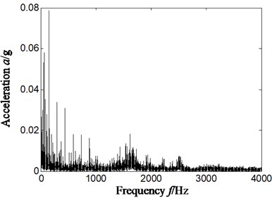
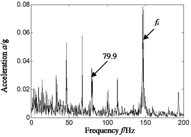
Experimental data was selected from June 3th, 2015. Firstly, rolling bearing inner ring and rolling elements compound faults experiment was simulated and acceleration signal was obtained and studied. We firstly took sensor installed on vertical upper of bearing chock as an example to study. The rotation speed was about 2000 r/min, and the result is shown in Fig. 4-Fig. 6. The specific rotating speed was 2013.4 r/min in Fig. 4-Fig. 6, and rotation frequency, outer ring characteristic frequency, inner ring characteristic frequency and rolling elements characteristic frequency was respectively 33.6 Hz, 86.1 Hz, 148.8 Hz and 58.4 Hz by calculation according to Eqs. (12-14). Fig. 4 is time-domain of acceleration signal. The Fig. 5(a) and Fig. 5(b) is respectively frequency spectrum and frequency spectrum local amplification of original signal. The Fig. 6(a) and Fig. 6(b) is respectively Hilbert envelope spectrum and its local amplification of original signal.
Fig. 4Time-domain of vibration acceleration signal
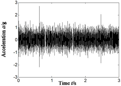
Fig. 5Frequency spectrum and its local amplification of original signal-sensor installation on vertical upper of bearing chock
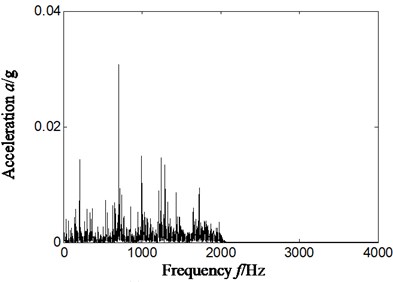
a) Frequency spectrum
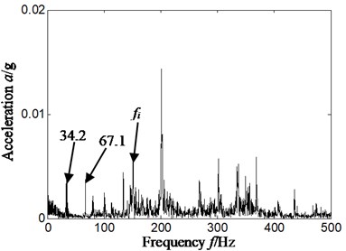
b) Frequency spectrum local amplification
Fig. 6Hilbert envelope spectrum and its local amplification of original signal-sensor installation on vertical upper of bearing chock
a) Hilbert envelop spectrum
b) Hilbert envelop spectrum local amplification
By analyzing Fig. 5 and Fig. 6, we only extracted inner ring feature frequency, but did not find rolling element characteristics frequency of rolling bearing by whether frequency spectrum or Hilbert envelope spectrum. That is, it cannot identify effectively compound fault types of rolling bearing whether frequency spectrum or Hilbert envelope spectrum.
5.2. Compound faults characteristic extraction of rolling bearing based on cyclostationary theory
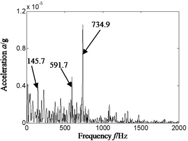
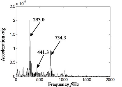
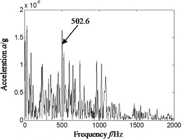
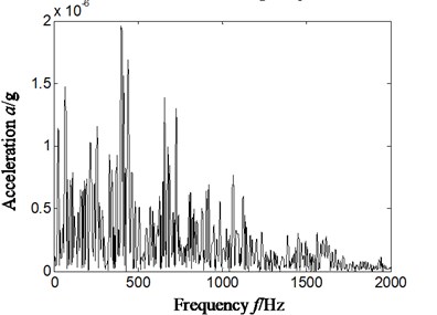
In order to further analyze characteristics extraction effect of cyclostationary theory for rolling bearing compound faults, Hilbert envelope spectrum of slice signal on different cyclic frequency of cyclic autocorrelation function was used to extract fault characteristics of rolling bearing. The result is shown in Fig. 7, and Fig. 7(a)-Fig. 7(d) is respectively slice signal’s Hilbert envelope spectrum on cyclic frequency equal to inner ring characteristic frequency and its twice and rolling elements characteristic frequency and its twice of rolling bearing.
Analyzing Fig. 7, it is obvious that we also cannot find rolling element characteristics frequency of rolling bearing by Hilbert envelope spectrum of slice signal on different cyclic frequency of cyclic autocorrelation function. Namely, satisfying result is difficult to obtain by cyclic statistics alone used to extract fault characteristics frequency of rolling bearing in the state of compound fault.
According to Fig. 5-Fig. 7, we can draw the conclusion that frequency spectrum, Hilbert envelope spectrum and cyclostationary theory alone cannot work effectively and correctly in extracting compound failure characteristics of rolling bearing.
5.3. Compound faults characteristic extraction of rolling bearing based on single-channel vibration acceleration signal according to proposed new method
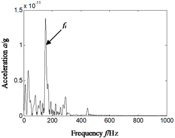
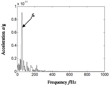
In order to obtain a satisfying result, we combined autocorrelation function and wavelet transform with cyclostationary theory, and selected data was consistent with Fig. 4-Fig. 7. Firstly, autocorrelation function of original vibration acceleration signal was obtained; secondly, wavelet transform was used to separate and reconstruct autocorrelation function to different frequency bands, db4 wavelet was selected, and decomposed levels of autocorrelation function were 4 levels; thirdly, slice signal of time-delay domain and cyclic frequency domain of obtained detail signal and approximate signal by wavelet transform was analyzed by cyclic autocorrelation function. Finally, Hilbert envelope spectrum was used to extract characteristics of slice signal, and compound fault characteristics and rules were extracted according to Hilbert envelop spectrum. The reconstruction signal and cyclic frequency was selected with better characteristics extraction effect, and signal selected from reconstruction detail signal d1, d2, d3, d4 and approximate signal a4 by wavelet transform, cyclic frequency position included characteristics frequency and its twice of rolling bearing. The result is shown in Fig. 8, and Fig. 8(a) and Fig. 8(b) is respectively slice signal’s Hilbert envelope spectrum on cyclic frequency equal to twice inner ring characteristic frequency based on reconstruction detail signal d4 and rolling elements characteristic frequency based on reconstruction approximate signal a4.
Fig. 7Hilbert envelope spectrum of original signal’s slice signal on different cyclic frequency position-sensor installation on vertical upper of bearing chock
a) Cyclic frequency equal to inner ring characteristic frequency
b) Cyclic frequency equal to twice inner ring characteristic frequency
c) Cyclic frequency equal to rolling element characteristic frequency
d) Cyclic frequency equal to twice rolling element characteristic frequency
Fig. 8Hilbert envelope spectrum of reconstruction signal’s slice signal on different cyclic frequency position-sensor installation on vertical upper of bearing chock
a) Cyclic frequency equal to twice inner ring characteristic frequency-based on d4
b) Cyclic frequency equal to rolling elements characteristic frequency-based on a4
In the precise analysis on Hilbert envelop spectrum according to proposed new method (Fig. 8), it can be seen that there exists outstanding characteristics frequency no matter inner ring or rolling elements. In comparison with Hilbert envelop spectrum above (Fig. 5-Fig. 7), the noise is reduced considerably, and what is more important is that not only inner ring characteristics frequency but also rolling elements characteristics frequency is outstanding. That is proposed new method has excellent feature extraction effect on compound faults of rolling bearing.
5.4. Sensors installation position effect on rolling bearing compound faults characteristics extraction
To compare the influence of installation position of sensor on compound faults characteristics extraction, we selected the experimental data collected in the same time with Section 5.1-5.3 for analysis, and conducted compound faults characteristic analysis on the signal collected by the acceleration sensors installed on horizontal right of bearing chock. The results are shown in Fig. 9-Fig. 10. Fig. 9 is time-domain signal of acceleration. Fig. 10(a) and Fig. 10(b) is respectively slice signal’s Hilbert envelope spectrum on cyclic frequency equal to inner ring characteristic frequency based on reconstruction detail signal d4 and two rolling elements characteristic frequency also based on reconstruction detail signal d4.
Fig. 9Time-domain of vibration acceleration signal-sensor installation on horizontal right of bearing chock
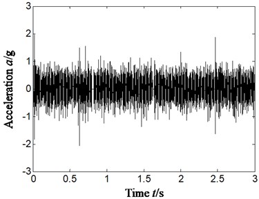
Fig. 10Hilbert envelope spectrum of reconstruction signal’s slice signal on different cyclic frequency position-sensor installation on horizontal right of bearing chock
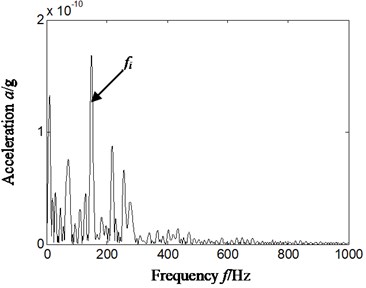
a) Cyclic frequency equal to inner ring characteristic frequency-based on d4
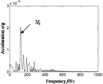
b) Cyclic frequency equal to twice rolling element characteristic frequency-based on d4
From Fig. 10(a) and Fig. 10(b), we can find there is more obvious feature frequency on cyclic frequency equal to inner ring and twice rolling element characteristic frequency, and it has consistency with Fig. 8. That is, if the cyclic frequency is equal to characteristic frequency of rolling bearing, the time-delay slice signal’s Hilbert envelop spectrum of autocorrelation function based on reconstruction detail or approximate signal of wavelet transform has been affected slightly by installation position of acceleration sensor.
5.5. Different types compound faults characteristics extraction of rolling bearing based on proposed new method
In order to verify proposed new method is effective on different compound faults mode of rolling bearing, another three compound faults types of rolling bearing were selected for study, the sensor installation on vertical upper of bearing chock. The three different compound faults of rolling bearing contain outer ring and rolling elements; inner ring and outer ring; inner ring, outer ring and rolling elements. The result is shown in Fig. 11-Fig. 13.
Fig. 11Outer ring and rolling element compound faults
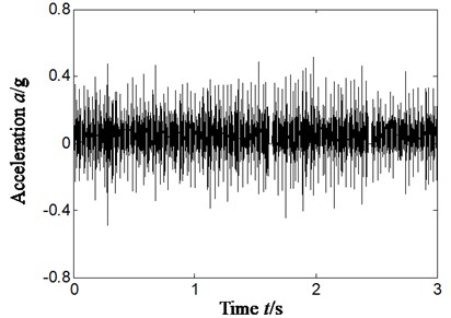
a) Time domain signal
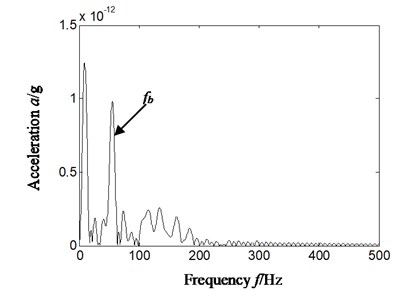
b) Hilbert envelope spectrum of reconstruction signal’s slice signal-cyclic frequency equal to rolling element characteristic frequency-based on a4
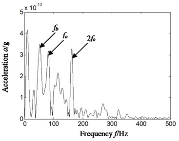
c) Hilbert envelope spectrum of reconstruction signal’s slice signal-cyclic frequency equal to outer ring characteristic frequency-based on a4
The Fig. 11 represents outer ring and rolling elements compound faults, and rotating speed is 1812.7 r/min. The inner ring characteristics frequency, outer ring characteristics frequency and rolling element characteristics frequency is respectively 133.9 Hz, 77.9 Hz and 52.3 Hz by calculation according to formula 12 to 14 and geometrical parameter of rolling bearing. Fig. 11(a)-Fig. 11(c) is respectively time domain of vibration acceleration signal, slice signal’s Hilbert envelope spectrum on cyclic frequency equal to rolling elements characteristic frequency based on reconstruction approximate signal a4 and outer ring characteristic frequency based on reconstruction detail signal a4.
The Fig. 12 represents outer ring and inner ring compound faults, and rotating speed is 1823.7 r/min. the inner ring characteristics frequency, outer ring characteristics frequency and rolling elements characteristics frequency is respectively 134.7 Hz, 78.0 Hz and 52.9 Hz by calculation according to geometrical parameter of rolling bearing and Eqs. (12-14). Fig. 12(a)-Fig. 12(c) is respectively time domain of vibration acceleration signal, slice signal’s Hilbert envelope spectrum on cyclic frequency equal to outer ring twice characteristic frequency based on reconstruction detail signal d4 and inner ring characteristic frequency based on reconstruction approximate signal a4.
The Fig. 13 represents outer ring, inner ring and rolling elements compound faults, and rotating speed is 2013.4 r/min. the inner ring characteristics frequency, outer ring characteristics frequency and rolling elements characteristics frequency is respectively 148.8.7 Hz, 86.1.0 Hz and 58.4 Hz by calculation according to Eqs. (12-14) and geometrical parameter of rolling bearing. Fig. 13(a)-Fig. 13(d) is respectively time domain of vibration acceleration signal, slice signal’s Hilbert envelope spectrum on cyclic frequency equal to twice outer ring characteristic frequency based on reconstruction detail signal d3, inner ring characteristic frequency based on reconstruction detail signal d3, twice rolling elements characteristics frequency based on reconstruction approximate signal a4.
From Fig. 11 to Fig. 13, we can find there is outstanding feature frequency based on proposed new method on another three different compound faults types of rolling bearing. That is, if the cyclic frequency is equal to characteristic frequency of rolling bearing, the time-delay slice signal’s Hilbert envelop spectrum of autocorrelation function based on reconstruction detail or approximate signal of wavelet transform can effective extract compound faults characteristic frequency of rolling bearing on different compound faults mode.
Fig. 12Outer ring and inner ring compound faults
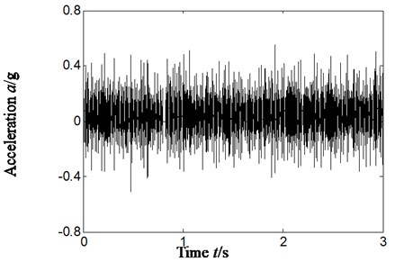
a) Time domain signal
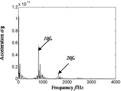
b) Hilbert envelope spectrum of reconstruction signal’s slice signal-cyclic frequency equal to outer ring twice characteristic frequency-based on d4
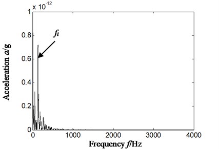
c) Hilbert envelope spectrum of reconstruction signal’s slice signal-cyclic frequency equal to inner ring characteristic frequency-based on a4
Fig. 13Outer ring, inner ring and rolling elements compound faults
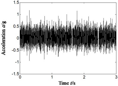
a) Time-domain signal
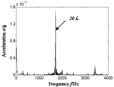
b) Hilbert envelope spectrum of reconstruction signal’s slice signal-cyclic frequency equal to twice outer ring characteristic frequency-based on d3
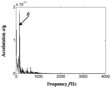
c) Hilbert envelope spectrum of reconstruction signal’s slice signal-cyclic frequency equal to inner ring characteristic frequency-based on d3
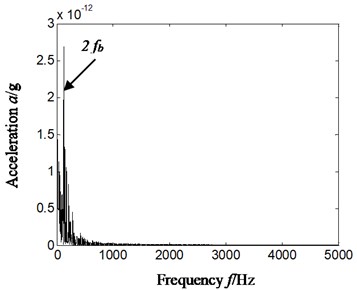
d) Hilbert envelope spectrum of reconstruction signal’s slice signal-cyclic frequency equal to twice rolling element characteristic frequency-based on a4
6. Conclusions
Rolling bearing fault mode usually shows compound faults in aero-engine, while many signal analysis methods have great limitation for compound fault characteristic extraction, and which leads to the difficulty to monitor the running state and to identify fault types of rolling bearing in aero-engine. To effectively and correctly extract compound fault characteristics of rolling bearing, a method of combining wavelet transform with cyclostationary theory, autocorrelation function and Hilbert transform is proposed and compared with frequency spectrum, Hilbert envelope spectrum and cyclic autocorrelation function alone. The result indicates that the proposed new method can correctly and effectively extract compound faults feature of rolling bearing in different compound faults modes only according to single-channel vibration acceleration signal; meanwhile, analysis has found sensors installation position has been effected slightly. The analysis also shows that regardless of frequency spectrum, Hilbert envelope spectrum, and cyclic autocorrelation function alone cannot correctly extract compound faults characteristics of rolling bearing, which usually leads to misdiagnosis and error diagnosis.
The method should require further study in terms of the following aspects:
Proposed method in this paper should be inspected in the actual project. The proposed method was inspected just by simulated data of the rotor-rolling bearing experiment rig. As the real aero-engine structure is far more complex than experiment rig, and there are a great of external noises and vibration in real flight, actual project inspection is required to determine the efficiency of extracting characteristics.
References
-
Wang Guobiao, He Zhengjia, Chen Xuefeng, et al. Basic research on machinery fault diagnosis – what is the prescription. Journal of Mechanical Engineering, Vol. 49, Issue 1, 2013, p. 63-72.
-
Zhang Ke, Zhou Donghua, Chai Yi Review of multiple fault diagnosis method. Control Theory and Applications, Vol. 32, Issue 9, 2015, p. 1143-1157.
-
Wang Cong Investigation on gear pitting corrosion fault diagnosis in gearbox based on Hilbert and cepstrum. Electric Power Science and Engineering, Vol. 27, Issue 3, 2011, p. 36-40.
-
Randall R. B., Antoni J., Chobsaard S. The relationship between spectral correlation and envelope analysis for cyclostationary machine signals, application to rolling bearing diagnostics. Mechanical Systems and System Processing, Vol. 15, Issue 5, 2001, p. 945-962.
-
Antoni J., Bonnardot F., Raad A., et al. Cyclostationary modeling of rotating machine vibration signals. Mechanical Systems and Signal Processing, Vol. 18, 2004, p. 1285-1314.
-
Antoni J., Guillet F., El Badaoui, Bonnardot, F. Blind separation of convolved cyclostationary processes. Signal Processing, Vol. 85, Issue 1, 2005, p. 51-66.
-
Ming Yang, Chen Jin, Dong Guangming Rolling bearing fault diagnosis based on cyclic wiener filter and envelop spectrum. Journal of Vibration Engineering, Vol. 23, Issue 5, 2010, p. 537-540.
-
Borghesani P., Pennacchi P., Ricci R., Chatterton S. Testing second order cyclostationarity in the squared envelope spectrum of non-white vibration signals. Mechanical Systems and Signal Processing, Vol. 40, 2013, p. 38-55.
-
Boungou D., Guillet F., Elbadaoui M. Fatigue damage detection using cyclostationarity. Mechanical Systems and Signal Processing, Vol. 1, 2014, p. 1-15.
-
Chen J., Zi Y., He Z., et al. Compound faults detection of rotating machinery using improved adaptive redundant lifting multiwavelet. Mechanical Systems and Signal Processing, Vol. 38, Issue 1, 2013, p. 36-54.
-
Abbasion S., Rafsanjani A. Rolling element bearings multi-fault classification based on the wavelet denoising and support vector machine. Journal of Mechanical Systems and Signal Processing, Vol. 21, 2007, p. 2933-2945.
-
Seshadrinath J., Singh B., Panigrahi B. K. Investigation of vibration signatures for multiple fault diagnosis in variable frequency drives using complex wavelets. IEEE Transactions on Power Electronics, Vol. 29, Issue 2, 2014, p. 936-945.
-
Ming Anbo, Chu Fulei, Zhang Wei Compound fault features separation of rolling element bearing based on the wavelet decomposition and spectrum auto-correlation. Journal of Mechanical Engineering, Vol. 49, Issue 3, 2013, p. 83-87.
-
Xu Yonggang, Meng Zhipeng, Zhao Guoliang Study on compound fault diagnosis of rolling bearing based on dual-tree complex wavelet transform. Chinese Journal of Scientific Instrument, Vol. 35, Issue 2, 2014, p. 447-452.
-
Peng Li, Fanrang Kong, Qingbo He, et al. Multiscale slope feature extraction for rotating machinery fault diagnosis using wavelet analysis. Measurement, Vol. 46, 2013, p. 497-505.
Cited by
About this article
This work was supported by The National Natural Science Fund (Grant No. 51605309), Provincial Education Department of Liaoning Province (Grant No. L201628) and Aviation Science Function (Grant No. 20163354004).
The author declares that there is no conflict of interest.
