Abstract
The modern market of transport services requires the saturation of the car fleet, a specialized type of construction designed to carry a special kind of cargo, for example, heavy cargo containers, various automotive equipment, etc. It is necessary to increase the speed of movement and safety of the goods carried. A review of the work related to the improvement of the running parts of freight cars showed that over the past 50 years a large number of different types of freight wagon carriages have been developed. At the same time, the main attention was paid to the improvement of individual elements during the creation of bogies, and the problem of the wear of the part of the trolleys was solved while preserving the unchanged ideologues lay in the CRI-Х3 trolley. However, the question of the choice of constructive schemes and rational parameters of the spring suspension of bogies is not completely resolved.
1. Introduction
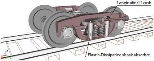
The most active in the creation of new generation trucks are OAO NPK Uralvagonzavod, OAO VNIIZhT, OAO VNIKTI, MIIT, OAO Altayvagon, ZAO Pomtraktor-Wagon [1], FSUE TsKB TM, JSC NEC Wagons, BSTU, etc. Current systems of spring suspension of freight wagon carriages do not meet modern requirements of operation and, even more so, are promising, i.е. Do not allow to increase the speed of the train [2, 3]. The studies carried out by the Department “Cars and Carriage Economy” of MIIT together with FSUE “TsKB TM” and OAO “Altayvagon” showed that the use of a separate scheme for suppressing vertical and horizontal oscillations in the spring suspension and using a special device-diagonal links to prevent the running of the side frames are expedient and, the experimental trolley of model 18-9945 has been developed [4, 5]. The analysis of foreign experience on the use of such devices in the construction of bogies shows the prospects of this direction [6]. Thus, the possibility of using a trolley similar to the design in specialized long-distance freight cars is an important task and becomes relevant with the requirements of increasing the speed of traffic and creating new generation cars with improved dynamic qualities [7, 8]. To study the dynamic quality of specialized long-distance freight cars on the basis of trolleys model 18-100 and 18-9945, an improved mathematical model describing the movement of straight and curved sections of the track using the “Universal Mechanism” software complex was developed [9, 10]. General views of the computer model of bogies are shown in Fig. 1 and 2. Mathematical models are constructed using a well-known approach, according to which a mechanical system is represented with a set of absolutely rigid bodies connected by means of hinges and power elements with nonlinear characteristics [11, 12].
2. Materials and methods
Equations of motion of a freight car are a system of second-order differential equations with nonlinear right-hand sides (in matrix form) and is written in a general form:
when – the number of generalized coordinates of the determining positions of the system ( 1-114);
– inertial parameter matrix;
– vector of generalized coordinates;
– a vector containing nonlinear dependences of the reactions on the coordinates and their derivatives;
– matrix-column of generalized forces that determine external influences on the system.
Fig. 1General view of a computer model of a typical trolley based on model 18-100
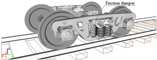
Fig. 2General view of the computer model of the experimental trolley on the basis of model 18-9945
A synthesis of systems of differential equations of motion was made using the analytical software environment of the software complex “Universal Mechanism”.
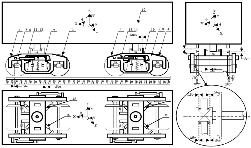
The calculation schemes of each car use nineteen solids, which have 114 degrees of freedom. The calculation scheme of the car on the model trolleys based on model 18-100 is shown in Fig. The scheme of numbering of bodies: 1, 2, 3, 4 – wheel pairs; 5, 6, 7, 8 – side frames 9, 10 – bolster beams; 11, 12, 13, 14, 15, 16, 17, 18 – friction vibration dampers; 19 – body. The calculation scheme of the car on the experimental trolleys is shown in Fig. The scheme of numbering of bodies: 1, 2, 3, 4 – wheel pairs; 5, 6, 7, 8 – side frames 9, 10 – bolster beams; 11, 12, 13, 14 – longitudinal guides; 15, 16, 17, 18 – traction; 19 – body.
In the spring suspension of an experimental trolley, two types of vibration dampers are used. Vertical ones are shock absorbers with viscous friction, horizontal ones are elastic-friction dampers of oscillations of constant friction. For computer simulation of a shock absorber with viscous friction, a bipolar power element was used in the “Universal Mechanism” software package. The element is a parallel-connected spring and a linear damper [1]. A generalized elastic linear force element was used to model springs of spring suspension. A bipolar force element was used to simulate an elastic-friction damper. This element is a parallel-connected spring and a friction element.
Fig. 3The calculation scheme of the car on trolleys of model 18-100 and ways
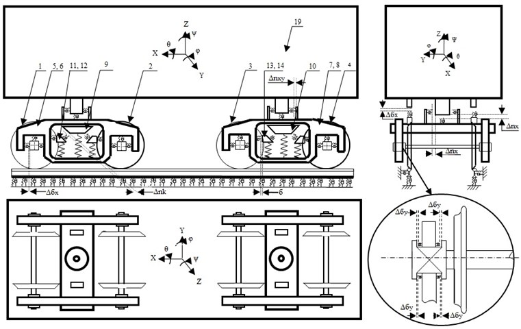
Fig. 4The calculation scheme of the car on the experimental trucks on the basis of the model 18-9945 and the way
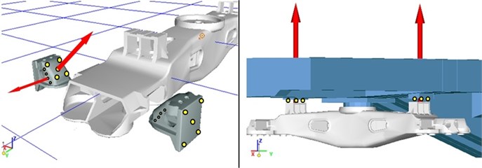
To model the work of structural links between the elements of the trolley (longitudinal leashes and diagonal links) special elastic elements were used [2]. A general view of the structural connections of the test bogie is shown in Fig. 5. In the spring suspension of a standard trolley, the vertical and horizontal vibrations are extinguished by friction wedge dampers. When constructing the wedge absorber model, 32 contact points associated with the contacting elements are created on the surface of the standard wedge. Similarly, a contact interaction was realized between the foot and the thrust bearing, in the skid unit and between the body slips and the bolster [3]. These models of structural connections allow for the account of wear between the foot and the thrust bearing, between the body slides and the bolster, the axle aperture in the longitudinal and transverse directions. A general view of the arrangement of the contact points on the wedge and in the slips, is shown in Fig. 6.
Fig. 5General view of the structural ties of the experimental trolley
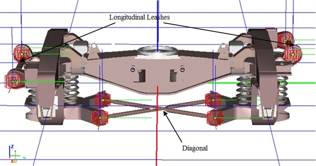
Fig. 6General view of the arrangement of contact points on the wedge and slips
To assess the reliability of the developed computer models, studies were carried out to determine the correspondence of the developed mathematical models to the real object, as well as to assess the adequacy of the selected parameters of constructive relationships. To determine the angular stiffness of the trolley, experimental studies have been carried out in the plan, the method and the results of experimental calculations are presented in [4]. To identify the parameters of the calculation model of the experimental truck, a separate subsystem-cart, imitating the experimental conditions, was isolated from the general mathematical model of the car. To the side frames were applied forces (diagonally), causing the bogie to skew with a certain angle of rotation of the bolster from its initial position around the axis . The scheme for applying loads is shown in Fig. 7.
The parametric identification procedure in this case was reduced to finding the parameters of the structural relationships of the mathematical model (stiffness of the longitudinal leashes and diagonal links), which ensure the best convergence of the calculated values of the moment of the shearing forces with the experimental values obtained for the same values of the angles of rotation of the supertor beam . Computer calculations to identify the parameters of the structural ties of the test car were carried out in three stages: 1 – a trolley without ties; 2 – trolley with longitudinal leashes; 3 – trolley with longitudinal leashes and diagonal ties. The oscillograms obtained in the calculation of the dependences of the moment of resistance to the displacement of the side frames of the bogie from the angle of rotation of the bolster are shown in Fig. 8.
Fig. 7The scheme of application of loads in the calculations for the identification of the parameters of the experimental trolley
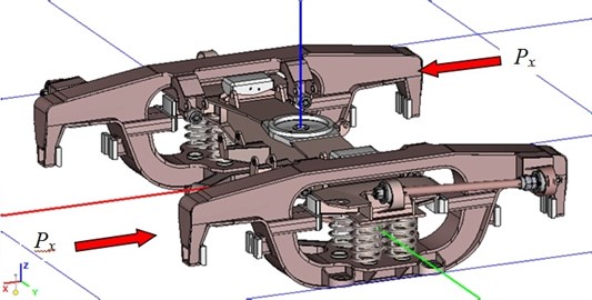
Fig. 8Oscillogram of the dependence of the moment of resistance to the shift of the side frames of the trolley on the angle of rotation of the sup- pressor beam; 1 – experimental trolley without connections; 2 – an experimental trolley with longitudinal leashes; 3 – an experimental trolley with longitudinal leashes and diagonal ties. 1, 2, 3 – stages of calculations; X – displacement of the side frames along the x axis; φ – is the angle of rotation of the bolster about the z axis; M – the moment of resistance to the shift of the side frame; Kφ – is the angular rigidity of the trolley in the plan
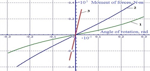
Table 1Comparison of calculated data with experimental data
Parameters | ||||
Name | \ \ | \ \ | \ \ | \ \ |
mm | rad | kN∙m | kN∙m∙rad-1 | |
Experiment | 60.9\52.0\6.0 | 0.030\0.025\0.003 | 22.6\39.46\31.68 | 748\1545\10750 |
Calculation | 60.5\52.5\6.2 | 0.030\0.026\0.0029 | 22.6\39.46\31.68 | 747\1546\10755 |
Comparisons of the calculation results with the experimental data are presented in Table 1. They show good convergence. The discrepancy does not exceed 3 %. From the data given (see Table 1), it can be seen that the parameters of the structural relationships affecting the angular rigidity of the trolley in the plan were chosen adequately [5].
3. Results and discussion
Complex quantitative and qualitative assessment, developed in the thesis of computer models of cars based on trolleys of models 18-100 and 18-9945, was carried out by comparing the calculation results with the experimental data obtained during complex dynamic tests of long-wheelbase platforms at the Belorechenskaya-Maikop high-speed range [6]. Comparative computer calculations were performed with vertical and lateral unevenness of the rail threads taken from the full-scale line of the Belorechenskaya-Maikop test range. Digital implementations of these irregularities were provided by VNIIZHTom.
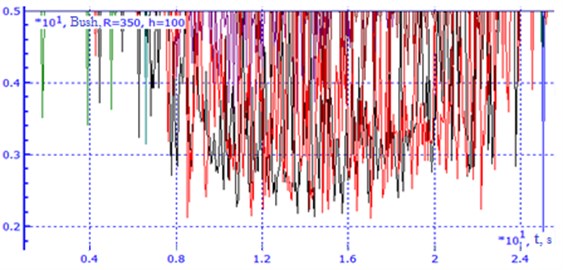
Fig. 9Comparison of experimental and calculated data on the values of the safety factor of stability from the derailment of the wheel from the rail (Bush) when the platform moves in a curve of radius 350 m with an elevation of 100 mm (empty mode)
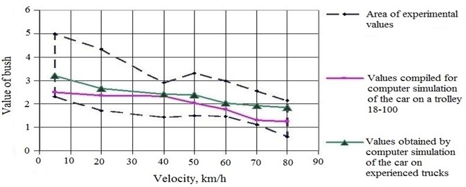
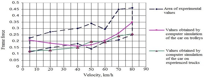
Based on the statistical information obtained as a result of the tests, the spread fields of the maximum values of the indicators were constructed, followed by the imposition of computer calculation results on them. Some comparative modeling results are presented in Fig. 9-10. The maximum discrepancies between the experimental and calculated data do not exceed 15 %.
Thus, the analysis of the results showed a satisfactory correspondence of computer simulation with experimental data, which indicates the reliability of the elaborated mathematical models of long-bodied cars developed in the dissertation, describing their movement in the straight and curved sections of the railway track [7].
Fig. 10Comparison of experimental and calculated data on the values of frame forces in fractions of the axial load when the platform moves in a curve of radius 350 m with an elevation of 100 mm (empty mode)
Multivariate calculations of the dynamic properties of long-bodied cars for the purpose of determining the rational parameters of the elements of spring suspension and special devices of the test bogie, taking into account the effect of real unevenness of the railway track [3, 4].
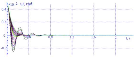
When determining the rational values of the resistance coefficients of the absorbers of the wagon vibration, the critical values of the resistance coefficients of shock absorbers (vibration dampers) for vertical and angular oscillations were determined. In “Norms” this value is recommended to be taken within 25-35 % of the critical one [8]. The critical values of the damper's resistance coefficients were determined on the basis of calculations of the car's own oscillations by integrating the general system of differential equations of the mathematical model with initial conditions corresponding to the initial deviation of the body from the static equilibrium position in the absence of external disturbances. The critical value of the drag coefficient of the absorber for angular oscillations was determined similarly [9]. In calculating the values at which the process of natural oscillations became aperiodic were fixed. Fragments of calculations are given in Fig. 11-12.
For vertical body oscillations, the critical value of the drag coefficient is significantly different from the critical values of the absorber resistance coefficient for angular vibrations. As a result of the series of calculations, a range of critical values of the absorber resistance coefficient was obtained (Table 2).
Fig. 11Oscillogram of vertical movements (bouncing) of the body of a laden car with a change in the drag coefficient in each (β) absorber from 50-275 kN×s/m
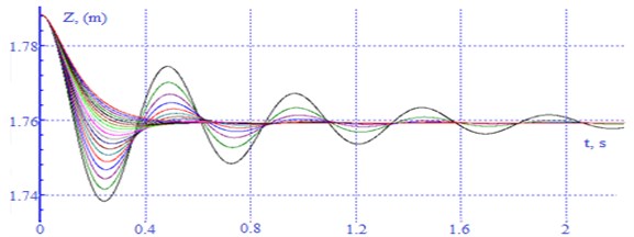
Fig. 12Oscillogram of angular movements (galloping) of the body around the y axis of a loaded car with a change in the drag coefficient in each (β) absorber from 20-150 kN×s/m
For more accurate determination of the rational value of the absorber’s resistance coefficient, the dynamic analysis of the car was analyzed at the next stage of the calculation with the range of the absorber’s resistance coefficient found [10]. The calculations were carried out at speeds of 40-120 km/h, taking into account the impact of real unevenness of the railway track in terms of the profile.
Table 2The total values of the coefficient of resistance of absorbers of oscillations of the car received in calculations of natural oscillations
Carriage loading parameters | The total critical value of the resistance coefficients of all car dampers (), kN×s/m | Values of 25-35 of critical | ||||
Empty | 830 | 870 | 240 | 208×290 | 218×305 | 60×85 |
Medium loaded | 1400 | 1750 | 560 | 350×490 | 438×612 | 140×196 |
Laden | 1800 | 4400 | 840 | 450×630 | 1100×1540 | 210×294 |
– bouncing, – lateral, – galloping | ||||||
Some results of dynamic indicators with varying values of the drag coefficient of absorbers at different speeds of the covered car for transportation of cars and a long platform for container transportation in empty and loaded mode are given in Table 3-4. From the analysis of the results it follows that such factors as the level of the frame forces, lateral forces, the vertical dynamics in the wheel-rail contact and the stability factors of the wheel against the departure from the rail head (Fig. 13) do not exceed the maximum permissible values in all calculated ranges of rational values at acceptable speeds.
Fig. 13Oscillogram of the stability factor of the covered car with variations in the drag resistance coefficient of the truck in a curve of radius 350 m with an elevation of 100 mm
The analysis of the obtained data showed that the rational value of the damping coefficient of a single absorber of vertical oscillations of a trolley of a covered car for the transport of cars is in the range of 52.5×87.5 kN×s/m (see Table 3).
Table 3Dependence of the coefficient of vertical wheel-rail dynamics on the resistance value of the vibration damper for various speeds of motion
Covered car loaded, curve of radius 650 m, height 100 mm | |||||||||
Velocity | 40 km/h | 50 km/h | 60 km/h | 70 km/h | 80 km/h | 90 km/h | 100 km/h | 110 km/h | 120 km/h |
17.5 kN×s/m | 0.444434 | 0.424418 | 0.566429 | 0.577036 | 0.598415 | 0.666714 | 0.736596 | 0.850221 | 0.848578 |
35.0 kN×s/m | 0.44469 | 0.425334 | 0.571248 | 0.575659 | 0.584215 | 0.655123 | 0.792238 | 0.852253 | 0.857656 |
52.5 kN×s/m | 0.447817 | 0.418646 | 0.562874 | 0.570917 | 0.589261 | 0.646535 | 0.753977 | 0.845448 | 0.861829 |
70.0 kN×s/m | 0.430833 | 0.435468 | 0.541044 | 0.560855 | 0.581393 | 0.645289 | 0.736079 | 0.830342 | 0.821966 |
87.5 kN×s/m | 0.420752 | 0.441989 | 0.576106 | 0.583541 | 0.630906 | 0.634239 | 0.742658 | 0.84574 | 0.82865 |
105.0 kN×s/m | 0.424418 | 0.439648 | 0.580629 | 0.599279 | 0.651834 | 0.635219 | 0.740247 | 0.84166 | 0.83666 |
122.5 kN×s/m | 0.450274 | 0.449922 | 0.587349 | 0.615525 | 0.665714 | 0.656378 | 0.747734 | 0.834959 | 0.829717 |
140.0 kN×s/m | 0.44861 | 0.471266 | 0.601693 | 0.593926 | 0.676103 | 0.698645 | 0.747637 | 0.84432 | 0.843985 |
157.5 kN×s/m | 0.461899 | 0.49014 | 0.542484 | 0.590788 | 0.697076 | 0.75715 | 0.751841 | 0.839886 | 0.842241 |
175.0 kN×s/m | 0.463156 | 0.525725 | 0.544434 | 0.598415 | 0.666714 | 0.786596 | 0.780221 | 0.848578 | 0.865225 |
192.5 kN×s/m | 0.465334 | 0.477606 | 0.56569 | 0.624215 | 0.655123 | 0.792238 | 0.802253 | 0.857656 | 0.878264 |
• In bold type, the minimum values of the frame forces are indicated • The underlined font indicates the maximum values of the frame forces | |||||||||
The rational value of the coefficient of resistance for one absorber of the test car of this car is 70.0 kN×s/m. The rational value of the coefficient of damping of a single absorber of vertical vibration () of a truck of a long-platform platform for container transportation in empty mode is in the range of 17.5×52.5 kN×s/m (see Table 4), and in the laden mode 52.5×70.0 kN×s/m. Thus, the rational value of the coefficient of resistance for one absorber of the test truck of the long-platform platform is 52.5 kN×s/m.
To assess the effect of the structural ties of the test truck on the dynamic parameters of the car and to choose their rational parameters, series of calculations were performed on straight and curved sections of the track [11]. In determining the rational parameters of the structural ties of the test car, the magnitude of the stiffness of the elastic element of the diagonal links was varied, which characterizes the angular stiffness of the trolley in the plan, and the dynamic characteristics of the car were analyzed.
Some graphs of the dynamic parameters depending on the angular rigidity of the test bogie in the plan in the range from 4000×14000 kN×m/rad at different speeds of the long-platform platform in the laden mode are given in Fig. 14-15.
Analysis of the results obtained showed that an increase in the angular stiffness of the trolley in the plan in the curved sections of the path does not significantly affect the vertical and frame forces, and in the straight sections of the path leads to an increase in the frame forces (see Fig. 14).
Table 4Dependence of the coefficient of vertical wheel-rail dynamics on the resistance value of the vibration damper for various speeds of motion
The car is empty, the curve of radius is 650 m elevation.100 mm | |||||||||
Velocity | 40 km/h | 50 km/h | 60 km/h | 70 km/h | 80 km/h | 90 km/h | 100 km/h | 110 km/h | 120 km/h |
17.5 kN×s/m | 0.201325 | 0.240313 | 0.273915 | 0.330657 | 0.362354 | 0.450461 | 0.65797 | 0.693719 | 0.749517 |
35.0 kN×s/m | 0.206532 | 0.244192 | 0.274979 | 0.333469 | 0.379456 | 0.495435 | 0.683274 | 0.686813 | 0.745464 |
52.5 kN×s/m | 0.208693 | 0.241714 | 0.287886 | 0.354456 | 0.386417 | 0.502154 | 0.646549 | 0.716434 | 0.787793 |
70.0 kN×s/m | 0.225853 | 0.250789 | 0.299404 | 0.370361 | 0.396483 | 0.513463 | 0.680147 | 0.738408 | 0.801781 |
87.5 kN×s/m | 0.237066 | 0.25246 | 0.300256 | 0.394563 | 0.413103 | 0.52156 | 0.711656 | 0.765321 | 0.846206 |
105.0 kN×s/m | 0.235715 | 0.269942 | 0.329056 | 0.401964 | 0.428551 | 0.530124 | 0.74242 | 0.782957 | 0.867672 |
122.5 kN×s/m | 0.244152 | 0.270504 | 0.330961 | 0.408897 | 0.425018 | 0.54511 | 0.75917 | 0.776059 | 0.867405 |
140.0 kN×s/m | 0.251395 | 0.29972 | 0.340078 | 0.424537 | 0.44613 | 0.543559 | 0.766429 | 0.780313 | 0.862498 |
157.5 kN×s/m | 0.27614 | 0.302874 | 0.355549 | 0.412054 | 0.465305 | 0.566237 | 0.771577 | 0.787117 | 0.870032 |
175.0 kN×s/m | 0.309013 | 0.343915 | 0.375657 | 0.463208 | 0.46797 | 0.567192 | 0.793096 | 0.786917 | 0.844635 |
192.5 kN×s/m | 0.254172 | 0.352979 | 0.393654 | 0.463065 | 0.473274 | 0.576813 | 0.754544 | 0.793664 | 0.866877 |
• In bold type, the minimum CD wheel values are indicated • The underlined font denotes the maximum values of CD wheel rail | |||||||||
Fig. 14Dependence of the frame forces on the speed and angular rigidity of the trolley in plan
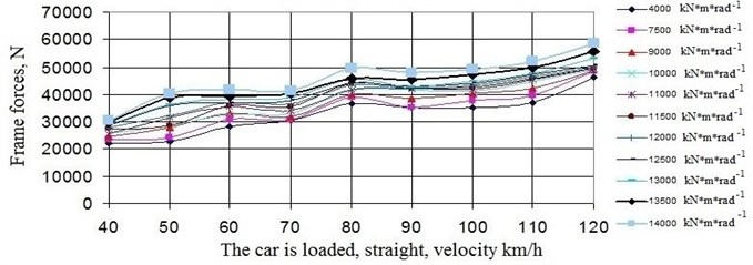
Fig. 15Dependence of the specific work of frictional forces in the wheel-rail contact on the speed and angular rigidity of the trolley in plan
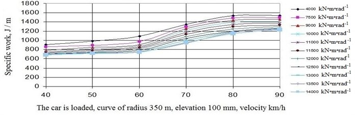
At the same time, it was found that an increase in the angular stiffness of the trolley in the plan in the curved sections of the path exerts a noticeable influence on the specific work of the frictional forces on the rim and crest of the wheels, i.e. significantly affects the wear in the wheel-rail system (see Fig. 15).
Thus, from the analysis of the obtained results of calculations it follows that it is expedient to have the angular stiffness of the experimental trolley in the plan in the range 12000×12500 kN×m/rad-1.
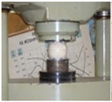
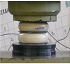
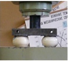
In the spring suspension of an experimental trolley [12], the possibility of using solid elastomeric shock absorbers as vibration dampers was investigated. To determine the elastic-dissipative characteristics of these shock absorbers, the author carried out experimental studies in the testing laboratory of the Department “Path and track economy” of the MIIT by the FU 100 machine (Fig. 16).
Fig. 16Loading scheme for testing elastomeric elements on a FU100 machine
a)
b)
c)
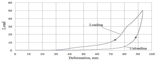
The tests were carried out according to three loading schemes (1-one element, 2-two elements in a vertically sequential position, 3-two elements in parallel in a sequential position - see Fig. 16). The tests consisted in compressing the elastomeric element by 10, 25 and 50 tons with a constant speed of 1 mm/s. The deformation of the elastomeric element was fixed [5]. One of the diagrams obtained in tests of 50 tons is presented in Fig. 17.
Thus, the results obtained make it possible to identify the parameters of spring suspension with elastomeric shock absorbers for the experimental truck more purposefully in order to improve the dynamic properties of long-bodied cars.
Comparative calculations of the dynamic characteristics of long-car wagons on typical and experienced trolleys in straight and curved sections are made taking into account the permissible unevenness’s of the railway track.
Fig. 17The diagram of one elastomeric element in tests of 50 tons
Some results of dynamic indicators of a covered car for transporting passenger cars on typical and experienced trucks are shown in Fig. 18-19.
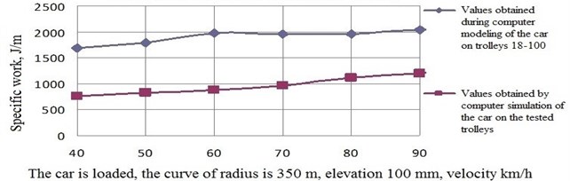
The analysis of comparative calculations of the dynamic characteristics of long-distance freight cars on typical and experimental trucks showed that the car on the experimental trolleys has significantly better dynamic performance in the straight and curved sections of the track. For example, the improvement in the dynamic qualities of a covered car for the transport of cars is achieved by the stability factor in a curve of radius of 650 m with an elevation of. 100 mm at speeds of 40×120 km/h in the range of 53×110 % (on average 81 % see Fig. 18), in frame forces – 15×53 % (on average by 34 %), in terms of the dynamics of the wheel - the rally – 11×84 % (on average by 47 %), the specific work of frictional forces in the contact wheel-rail – 48×59 % (on average 53 %), and the specific work of frictional forces in the wheel-rail contact in a curve of radius of 350 m with a ref. 100 mm – 78×128 % (on average by 103 % – see Fig. 19).
Fig. 18Dependence of the safety factor on the speed
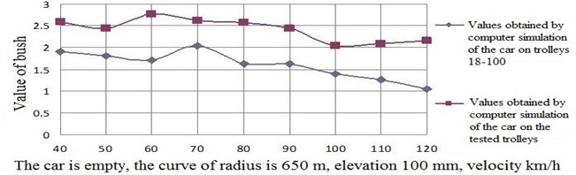
Fig. 19Dependence of the specific work of frictional forces in the wheel-rail contact on the speed
4. Conclusions
1) The review of the works related to the improvement of the dynamic qualities of freight cars showed that over the last years a large number of models of bogies have been developed and among them the most promising is the model 18-9945, since the characteristic feature and advantage of this bogie is the use of a separate scheme for suppressing vertical and horizontal vibrations and the use of special devices (longitudinal leashes and diagonal ties). The carried out analysis of foreign experiments on the use of such devices in the construction of bogies also shows the prospects of this direction.
2) To find ways to improve the dynamic qualities of long-distance freight cars, refined mathematical models were developed that describe their movement on trolleys of models 18-100 and 18-9945 in straight and curved sections of the track using the PC “UМ”. The proposed mathematical models allow:
– carry out extensive studies of the dynamic qualities of wagons when moving in straight and curved sections of the track, taking into account the impact of unevenness of the rail threads;
– to assess the impact of wear and tolerance on the geometric dimensions of the car and the failure of individual elements of the running parts to the dynamic quality and safety of traffic;
– to estimate the influence of deviations in the technical content of the track gauge on the dynamic parameters of the car;
– to select the rational parameters of the geometric, inertial, stiffness and damping characteristics of the cart and wagon elements.
3) To investigate the possibility of applying a separate scheme for damping vertical and horizontal oscillations and using longitudinal leashes and diagonal links in spring suspension, the refined mathematical models of long-distance freight cars on test bogies (models 18-9945) were first developed describing the motion along real road irregularities.
4) Theoretical and experimental studies were carried out to determine the angular stiffness of the experimental trolley. Multivariate calculations have been carried out to identify the parameters of the model of the bogie and its structural connections. The results of computer simulation are close to the experimental data, which shows the adequacy of the selected parameters. Divergences do not exceed 3 %.
5) Comparison of the results of calculation and experiment on the stability factor, frame forces, the dynamic coefficient showed their satisfactory coincidence, which indicates the reliability of the developed mathematical models of cars. The discrepancy does not exceed 15 %.
6) Experimental bench studies were performed to determine the parameters of elastic-dissipative properties of solid elastomeric shock absorbers. As a result, their stiffness and dissipation characteristics were obtained.
7) Conducted complex multivariate calculations on the choice of rational parameters of the elements of spring suspension and structural ties of the experimental truck for long-car wagons made it possible to establish the following rational parameters that allow improving the dynamic qualities of long-bodied wagons:
– coefficient of resistance of vertical vibration dampers of the test car of a covered car for transporting cars in the range of 52.5×87.5 kN×s/m (rational value is 70.0 kN×s/m);
– coefficient of resistance of vertical vibration dampers of the test truck of long-platform platforms for container transportation in the range of 35.0×70.0 kN×s/m (rational value is 52.5 kN×s/m);
– rigidity of one set of springs for spring suspension of an experimental truck of long-distance cars – vertical 2870×3000 kN/m, horizontal – 3350×3550 kN/m;
– the angular rigidity of the test car in terms of (taking into account all the connections) for long-car wagons in the range 12000×12500 kN×m/rad.
8) Comparative calculations of the dynamic characteristics of long-distance freight cars on typical and experimental trucks showed that the car on the experimental trolley has significantly better dynamic performance in the straight and curved sections of the track: in terms of safety factor – by 68 %, in frame forces – by 38 %, by coefficient wheel-rail dynamics – by 62 %, according to the specific work of frictional forces in the wheel-rail contact – by 80 %, i.e. we have a guaranteed improvement in dynamic qualities by an average of 60 %.
References
-
Kossov V. S. Proc. of VNIKTI on developing of three-element truck for freight cars with axial load 245 kN. Problems of Mechanics of Railway Transport. Dnepropetrovsk, 2004, p. 45-65.
-
Simonov V. A., Kovalyov R. V., Kotov S. V., Yefimov V. P. Influence of parameters on axle-box adapters for 18-100 type truck on indicators of wear of wheel pairs bandages and stability of movement of freight cars. BSTU Bulletin, Vol. 1, Issue 1, 2004, p. 147-155.
-
Yefimov V. P., Pranov A. A. Development and carrying out of complex testing of truck of model 18-578. Problems of Mechanics of Railway Transport, Dnepropetrovsk, 2004, p. 123-135.
-
Pranov A. A., Yefimov V. P. Modernization of truck of model 18-100 as effective way of increasing traffic safety of trains. Heavy Mechanical Engineering, Vol. 12, 2003, p. 75-85.
-
Houthis V. D., Anisimov P. S. Power characteristics of frictional wedge-type shock absorbers in mathematical models of studying freight cars. VNIIZhT Bulletin, Vol. 4, 2005, p. 127-133.
-
Pogorelov D. Yu Introduction to modeling of the systems dynamics of freight cars. Bryansk BSTU, 1996, p. 150-156.
-
Solonenko V., Mahmetova N., Musayev J., Kvashnin M., Alpeisov A., ZhauytA. Some aspects of the experimental assessment of dynamic behavior of the railway track. Journal of Theoretical and Applied Mechanics, Vol. 55, Issue 2, 2017, p. 421-432.
-
Solonenko V., Mahmetova N., Musayev J., Kvashnin M., Zhauyt A., Buzauova T. Modeling of dynamic characteristics of freight car with optimized parameters of wedge-type shock absorber. Journal of Vibroengineering, Vol. 19, Issue 2, 2017, p. 1197-1213.
-
Musayev J., Zhauyt A., Nurymov Y., Mamatova G., Adilkhanov Y., Alizhan A., Chigambaev T. The influence of operational factors on the contact-fatigue effect of couple of wheel-rail friction in curves of small radius. Vibroengineering Procedia, Vol. 8, 2016, p. 263-268.
-
Musayev J., Zhauyt A., Sagatbek M., Matikhan N., Kaliyev Y., Naurushev B. Seismic resistance of horizontal underground openings in anisotropic rocks. Vibroengineering Procedia, Vol. 8, 2016, p. 231-236.
-
Abilkaiyr Z., Musayev J., Kaiym T., Alpeisov A., Alimbetov A., ZhauytA. The interaction of the freight car and way taking into account deformation of assembled rails and sleepers. Vibroengineering Procedia, Vol. 8, 2016, p. 269-274.
-
Musayev J., ZhauytA. Analysis of disturbing influence of traffic load on soil body. Advances in Materials Science and Engineering, 2015, p. 1-7.
About this article

