Abstract
In order to solve the problem that the aperture of the small hole part is too small and the irregular shape of the surface is difficult to be processed. A solid - liquid two - phase abrasive grain polishing method is proposed. Based on the standard model and SIMPLEC algorithm, the numerical simulation of the surface of the micro – holes were carried out under different inlet speed conditions. The change of the turbulence kinetic energy, dynamic pressure and turbulence intensity of the micro – holes flow channel with the inlet velocity is discussed. The quality control law of the inlet velocity on the sol-id-liquid two-phase abrasive flow polishing. In order to verify the accuracy of the numerical analysis, the necessary solid-liquid two-phase flow polishing test was carried out with the micro-hole parts. The surface roughness of the inner surface of the micro-holes before and after polishing was tested. The results show that the surface roughness is reduced from 1.702 before polishing to 0.303 after polishing. The solid - liquid two - phase abrasive flow machining can effectively improve the surface quality of micro – holes.
1. Introduction
With the increasing development of science and technology, micro-hole parts in the aerospace, automobile manufacturing, mold manufacturing, textile machinery and other fields have a wide range of applications as: the car engine nozzle, textile machinery on the precision parts spinneret, extrusion molds and medical equipment [1]. However, due to the small pore size of small holes and irregular shape, the traditional polishing technology is difficult to effectively polish its inner surface, especially for the surface quality requirements of small hole parts, its ultra-precision machining is even more difficult, the abrasive flow processing technology can be used for the finishing of the inner surface of micro-hole parts because of its good fluidity and consistency [2-6]. Therefore, domestic and foreign scholars have carried out a series of research work on micro-hole processing technology. In this paper, the micro – holes were polished by solid-liquid two-phase abrasive flow polishing method and the numerical simulation was carried out. The effects of different inlet pressure on the dynamic pressure, turbulent kinetic energy and turbulence intensity of the perforated brass pipe were analyzed. At the same time, the inner surface was subjected to abrasive flow machining test under different pressure processing conditions. The surface analysis of the parts is carried out to verify the accuracy of the numerical simulation results, which can provide technical support for the future use of abrasive flow technology to polish tiny holes [7-10].
2. Numerical analysis of solid-liquid two-phase abrasive flow machining
2.1. Selection of turbulence models
For the solid-liquid two-phase abrasive flow machining, the turbulent state of the fluid has an important effect on the processing effect. Therefore, it is necessary to select the appropriate turbulence model to improve the accuracy of numerical analysis. Using the standard - turbulence model, this model is proposed by Launder et al. [11]. The flow analysis of the - turbulence model for solid-liquid two-phase flow media can reflect the main turbulence characteristics of the two-phase flow medium. The equations for the turbulent kinetic energy and the turbulence dissipation rate are as follows:
where is the laminar flow coefficient, is the turbulent viscosity coefficient, , is the turbulence kinetic energy generated by the laminar velocity gradient, where the empirical coefficients 1.44, 1.92, 0.09, 1.0, 1.3.
2.2. Calculate objects and meshing
The simulation model selected in this paper is a small hole part with diameter of 0.75 mm. It is modeled in solid works, meshed into ICEM for meshing, and more detailed hexahedral mesh is used to increase the calculation accuracy. The grid model is shown in Fig. 1.
Fig. 1Grid model

2.3. Numerical analysis of the initial conditions set
In this paper, the inner surface of micro-holes in solid-liquid two-phase abrasive flow machining is numerically simulated. Using fluent as the calculation platform, the SMPLEC algorithm of pressure coupling equation is calculated by using 3D single-precision steady-state implicit pressure solver. The turbulence model is based on the standard - turbulence model and the two-phase flow model is Mixture model. In the boundary condition, the inlet is the diameter of the left hole of 1.5 mm, the inlet condition is the velocity inlet, the direction is perpendicular to the boundary, the initial turbulence intensity is 5 %, the turbulent viscosity is 1, the solid phase is sic abrasive grain volume 0.1, Exit for the right side of the hole, the exit set to outflow, the rest of the border for the wall, wall selection no border slip.
The physical properties of the solid and liquid phase materials are set before numerical analysis. The specific parameters are shown in Table 1.
Table 1Setting of initial condition
Physical quantity | Value | Additional illustrate |
Ambient pressure (Pa) | 1.01e5 | Operating pressure |
Density of liquid phase (kg/m3) | 886 | Room temperature (293.15 K) |
Liquid kinetic viscosity (Pa∙s) | Changing with processing temperature | |
Liquid phase specific heat capacity / (kg∙K) | 2000 | |
Liquid phase conduction coefficient / (m∙K) | 0.15 | |
Gravitational acceleration (m∙s-2) | 9.81 | Vertical direction |
Particle concentration (kg/m3) | 3100 | Room temperature (293.15 K) |
Particles conduction coefficient / (m∙K) | 120 | |
Particle viscosity Pa∙s | 5e-6 | Relatively small to be ignored |
2.4. Numerical analysis and discussion of results
The turbulence and dynamic pressure of the fluid under different inlet velocities are numerically analyzed by fluid dynamics software. Numerical simulations were carried out for changes in flow rate. The speeds are set to 40 m/s, 50 m/s, 60 m/s, 70 m/s, respectively. The axial cross section of the workpiece is taken as the observation cross section to obtain the turbulent kinetic and dynamic pressure and turbulence intensity distribution clouds of the axial cross section at different inlet velocities as shown in Fig. 2 and Fig. 3 and Fig. 4.
Fig. 2Turbulent kinetic energy distribution at different inlet velocities
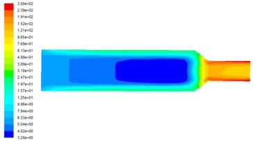
a) Inlet velocity is 40 m/s
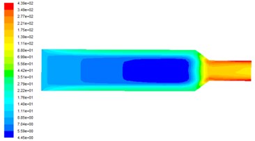
b) Inlet velocity is 50 m/s
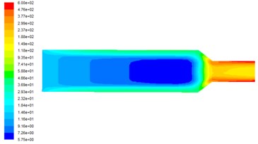
c) Inlet velocity is 60 m/s
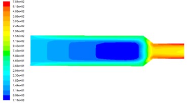
d) Inlet velocity is 70 m/s
Fig. 2 shows the distribution of turbulent kinetic energy on the observed surface at different inlet velocities. It can be seen from Fig. 2 that the turbulent kinetic energy in the middle of the flow channel is small and cannot play the role of polishing. The turbulent kinetic energy in the near-wall area is larger and the turbulent energy is closer to the wall, where the abrasive flow has strong centrifugal of the pulsating speed, and the bubble collision wall rupture of the release of energy is also passed to the abrasive, in order to achieve a good polishing effect. With the increasing speed of the entrance, the turbulence can also be greatly improved in numerical value. This is because the higher the inlet speed is, the higher the degree of fluid turbulence in the basin, the higher the degree of pulsation and the greater the turbulence, thus the more abrasive grain polishing effect.
Fig. 3 shows the dynamic pressure distribution at on the observed surface at different inlet velocities. Dynamic pressure determines the removal efficiency of the material. The dynamic pressure of the middle part of the runner is small and the polishing ability is weak, and the dynamic pressure increases obviously in the aperture change of the workpiece and the dynamic pressure is the largest in the small hole area, so the polishing effect of the abrasive flow is the best. With the increase of the inlet speed, the dynamic pressure also increases in the numerical value. Therefore, increasing the inlet speed can effectively improve the polishing efficiency of the abrasive flow machining.
It can be seen from the turbulence intensity cloud diagram with different inlet velocities at different inlet velocities in Fig. 4. The area with large turbulence intensity is mainly concentrated at the outlet orifice, and the turbulence intensity in the middle of the flow channel is small, and the middle part of the runner in the radial direction of the turbulence intensity is less than the wall near, which is conducive to the processing of the surface to remove the burrs. From the Fig. 4, show that the turbulence intensity increases in numerical order as the inlet speed increases, so that the inlet Speed is conducive to improving the polishing effect.
Fig. 3Dynamic pressure distribution at different inlet velocities
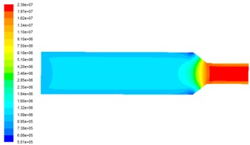
a) Inlet velocity is 40 m/s
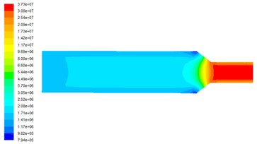
b) Inlet velocity is 50 m/s
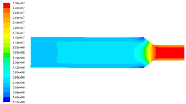
c) Inlet velocity is 60 m/s
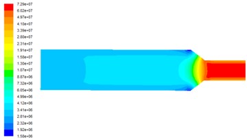
d) Inlet velocity is 70 m/s
Fig. 4Turbulence intensity distribution at different inlet velocities
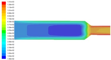
a) Inlet velocity is 40 m/s
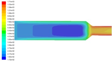
b) Inlet velocity is 50 m/s
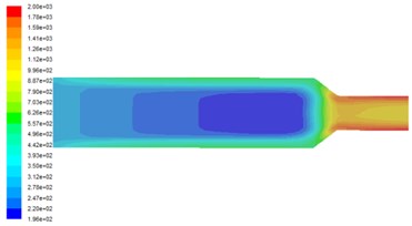
c) Inlet velocity is 60 m/s
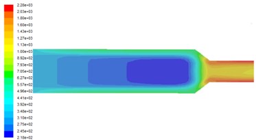
d) Inlet velocity is 70 m/s
3. Experimental analysis of solid-liquid two-phase abrasive grain polishing
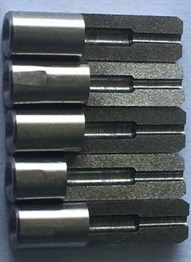
In this experiment, sic abrasive with particle size of 200 was prepared with 10 % body weight and hydraulic oil uniform, and the micro-holes abrasive was polished at 40, 50, 60 and 70 m/s for 5 min, dispose of the parts after processing, after cutting the parts shown in Fig. 5.
Fig. 5The parts after cutting
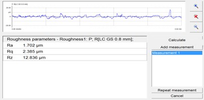
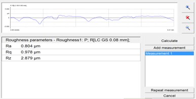
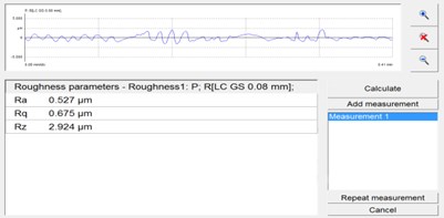
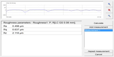
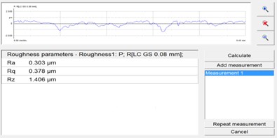
The surface roughness of the micropores was measured by grating surface roughness measuring instrument, in order to evaluate the effect of abrasive grain polishing technology on the roughness more accurately, the inlet with good processing effect and the exit part with poor polishing quality are selected. The middle part of the sample flow channel is selected and the roughness detection is shown in Fig. 6.
Fig. 6The surface roughness of the workpiece before and after processing
a) Original 1 #
b) Sample 2 #
c) Sample 3 #
d) Sample 4 #
e) Sample 5#
Fig. 6 shows the surface roughness of the workpiece before and after processing. After the abrasive flow processing, the workpiece roughness Ra is 0.804 μm, 0.527 μm, 0.498 μm, 0.303 μm, the surface roughness of the micropores after the abrasive flow machining is obviously reduced, and the roughness decreases with the increase of the inlet speed. This also proves the effectiveness of solid-liquid two-phase abrasive grain flow machining. It can be seen that it is possible to increase the wear speed of the abrasive flow machining to increase the wear quality of the abrasive flow.
4. Conclusions
In this paper, in order to solve the problem that the aperture of small hole parts is too small and the shape is irregular, it is difficult to finish the finishing of its inner surface the method of solid-liquid two-phase abrasive flow polishing on the inner surface of micro-holes is proposed. The numerical conclusions and experimental results are given.
1) In the process of solid-liquid two-phase abrasive grain polishing, the inlet velocity is the main influencing factor. The speed of continuous increase in the flow of small holes within the dynamic pressure, turbulent kinetic energy also increases, abrasive grain polishing effect also will change better.
2) The surface roughness of the inner surface of the micropores after processing at different processing speeds was found. The roughness after Ra 1.702 μm was about Ra 0.303 μm, and the surface quality was improved obviously. Phase grinding grain polishing technology can effectively improve the internal surface quality of micro-hole parts, for the small hole parts of the inner surface finishing has a certain reference value.
References
-
Ying Renlong, Zeng Liqun, Gu Daqiang Micro-hole processing technology overview. Machine Tool and Hydraulics, Vol. 6, 2008, p. 144-147.
-
Li Junye Micro-Hole Abrasive Grain Polishing Device Development and Technology Research. Changchun University of Science and Technology, 2011.
-
Li Junye, Dong Kun, Wang Xinghua, et al. Molecular dynamics simulation research into generative mechanism of particles micro-cutting surface. Journal of Mechanical Engineering, Vol. 17, 2016, p. 94-10.
-
Li Junye Yang Lifeng Liu Weina, et al. Experimental research into technology of abrasive flow machining nonlinear tube runner. Advances in Mechanical Engineering, Vol. 6, 2015, p. 752353-752353.
-
Ji Shiming, Qiu Yi, Cai Yaojie, et al. Research on mechanism of ultrasound enhancing and the experiment based on softness abrasive flow. Journal of Mechanical Engineering, Vol. 7, 2014, p. 84-93.
-
Ji Shiming, Ma Baoli, Tan Dapeng Numerical analysis of soft abrasive flow in structured restraint flow passage. Optics and Precision Engineering, Vol. 19, Issue 9, 2011, p. 2092-2099.
-
Jishi Ming, Youzhi Fu, Tan Dapeng, et al. Study on dynamic characteristics of two-phase abrasive flow based on shear stress transport turbulent model. Aata Armamentarii, Vol. 33, Issue 4, 2012, p. 443-450.
-
Gao Hang, Wu Mingyu, Fu Youzhi, et al. Development of theory and technology in fluid abrasive finishing technology. Journal of Mechanical Engineering, Vol. 7, 2015, p. 174-187.
-
Bremerstein T., Potthoff A., Michaelis A., et al. Wear of abrasive media and its effect on abrasive flow machining results. Wear, Vol. 342, Issues 343-15, 2015, p. 44-51.
-
Venkatesh G., Tarlochan Singh, Apurbba Kumar Sharma, Akshay Dvivedi Finishing of micro-channels using abrasive flow machining. Springer India, Vol. 4, 2014, p. 243-252.
-
Launder B. E., Spalding D. B. Lecture in Mathematical Models of Turbulence. Academic Press, London, 1972.
Cited by
About this article
The authors would like to thank the National Natural Science Foundation of China No. NSFC 51206011, Jilin Province Science and Technology Development Program of Jilin Province No. 20160101270JC and No. 20170204064GX, Project of Education Department of Jilin Province No. 2016386. At the same time, thanks for the Hi-Key Technology Company to provides a trial version of EDEM software.
