Abstract
In this paper, we focus on the stability of the hydropower plant with sharing tailrace surge tank. Considering the interaction between hydro-turbines and time-delay of hydraulic servo system, a nolinear dynamic model of multi-hydro-turbine governing time-delay systems with sharing tailrace surge tank is first established. The model can predict the transient characteristic of the hydro-turbine governing system, promoting the development of transient analysis, and safe operation of the governing system. Then, bifurcation characteristics of the system with different governor parameters and time-delays are studied. Moreover, the effect of time-delay on the stability intervals of governor parameters are investigated and its optimal value with different time-delays are obtained. All of the above analytical results can provide theoretical guidance for the actual operation of a hydropower plant with sharing tailrace surge tank.
1. Introduction
Hydropower is a low cost, near zero pollutant emissions renewable energy source, and can respond to peak loads quickly [1-3]. With the rapid development of hydropower [4-7], the underground powerhouse of hydropower plant is widely used. In view of the overall design, excavation engineering and other reasons, it usually adopts the structure of multi-hydroelectric generating units with sharing tailrace surge tank [8, 9]. Due to this arrangement, hydro-turbines are related to each other, which has a great impact on the hydro-turbine governing system and may cause the abnormal vibration of the units [10]. Moreover, the governing system is directly controlled by the hydro-turbine governor to realize different transient processes [11-13]. In the actual operation, the displacement response of the servomotor piston has a lag in time and the dead zone of the main control valve causes the servomotor to remain stationary [14]. These affect the bifurcation characteristics and the stability of the hydro-turbine governing system. Considering the above factors, it’s necessary to study the stability of multi-hydro-turbine governing systems considering time-delay.
Fortunately, there are some contributions about the stability and time-delay effect of the hydro-turbine governing system [15-20]. For example, Zeng [15] integrated the generator equations and shafting lateral vibration into the generalized Hamiltonian system. Then the generalized Hamiltonian control model is proposed for hydro-turbine generating sets in the shafting transient state. Guo [16] established a hydro-turbine governing system with sloping ceiling tailrace tunnel, and the stability of the system considering different factors are analyzed based on stable domain. Nagode [17] assessed the relationship between random gate position and the hydro-turbine deviated power on random water disturbance and load variation, the deviated power can tracks deviated power target signal accurately. Xu and Wang [21, 22] discussed the influence of fractional-order and time-delay on the hydro-turbine governing system with single unit, and their changing law was respectively identified. However, the influence of time-delay on the hydropower plant with sharing tailrace surge tank has not been discussed, considering the complexity of the above hydropower plant during the regulation process. It is necessary to study the effect of time-delay on the stability of the multi-hydro-turbine governing systems with sharing tailrace surge tank.
Motivated by the above discussions, considering the continuous oscillation process that may occur during the operation of a multi-hydroelectric generating unit with sharing tailrace surge tank, and the displacement response of servo piston in hydraulic servo system has a lag in time, we first introduce the time-delay to the multi-hydro-turbine governing systems with sharing tailrace surge tank. Second, the stable domain of the system without time-delay is presented. Third, the bifurcation characteristics of the system with different governor parameters and time-delays are analyzed. Finally, the stability intervals and optimal value of governor parameters with different time-delays are exhaustively investigated.
2. Multi-hydro-turbine governing time-delay systems with sharing surge tank
To illustrate the interaction between hydro-turbines in the hydropower plant, a general layout of a hydropower plant with sharing tailrace surge tank is shown in Fig. 1. From Fig. 1, each hydroelectric generating unit has independent water pipe and upstream surge tank. After the water flow through the rotating parts, it converges inside the tailrace surge tank. When it is in a steady state, the flow in the pipe is relatively stable, and each hydroelectric generating unit is in a transient relative equilibrium state.
Fig. 1The general layout of a hydropower plant with sharing tailrace surge tank
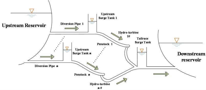
In the operation of a hydropower plant with sharing tailrace surge tank, the small disturbance of the system can be counteracted by the dead zone. However, if one of the units is subjected to a large dynamic adjustment, the flow of this unit will change accordingly. Subsequently, due to the inertial action of the fluid, the flow and pressure at the tailrace surge tank will also change. Other units will make the discharge changes in response to these changes, and thus have an impact on the unit, forming a process of repeated regulation eventually [23]. Therefore, the dynamic process of continuous oscillation is common for hydropower plant with sharing tailrace surge tank.
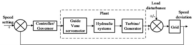
The structure diagram of the hydro-turbine governing system is shown in Fig. 2 [24] and its fundamental equations are listed in Section 2.1 to Section 2.4. In Section 2.5, the nonlinear dynamic model of multi-hydro-turbine governing time-delay systems with sharing tailrace surge tank is established.
Fig. 2The structure diagram of Francis hydro-turbine governing system
2.1. Pipe network
For the hydropower plant with sharing tailrace surge tank, suppose there are altogether units of hydro-turbine. In this paper, the momentum equation of the th diversion tunnel can be described as [10]:
The continuity equation of the th surge tank:
The momentum equation of the th penstock:
2.2. Hydro-turbine
The dynamic model of the th hydro-turbine can be described as [19]:
where , , , and , the operation parameters of the th hydro-turbine, denote the relative deviations of the hydro-turbine torque, the hydro-turbine flow, the hydro-turbine head, the rotate speed and the guide vane opening, respectively. , and are the partial derivatives of the hydro-turbine torque with respect to the hydro-turbine head, the hydro-turbine speed and the guide vane opening. Similarly, , and denote the partial derivatives of the hydro-turbine flow with regard to the hydro-turbine head, the hydro-turbine speed and the guide vane opening, respectively.
2.3. Generator system
The first-order generator model is introduced for the sake of simplicity, and its mathematical equation is presented as [25]:
where , and denote the inertia time constant of generator and load, respectively. is the synthetic self-regulation coefficient, is the load disturbance of the th hydro-turbine.
2.4. Hydraulic servo system with time-delay
The servomotor is used to amplify the control signal and supply power for operating the guide vane. The mathematical model of hydraulic servo system can be written as [26]:
where is the major relay connecter response time of hydraulic servo system. is the output signal of the hydraulic servo model, and its equation can be written as:
where is the frequency disturbance. is the intermediate variable, .
In actual operation of hydropower station, considering the fact that the hydraulic servo system exists time lag, a discrete time-delay is introduced to the mathematical model of the hydraulic servo system and it can be expressed as [21]:
2.5. System mathematical model
From Eqs. (1)-(8), the nonlinear dynamic model of multi-hydro-turbine governing time-delay systems with sharing tailrace surge tank is:
and:
3. Stability analysis
Taking a hydropower plant with sharing tailrace surge tank as an example [27], the stability of the system are researched in the subsequent. The hydropower plant has two hydroelectric generating units of the same type ( 2), and the corresponding parameters of pipeline and upstream surge tank are also same. In the following, we assume that unit 1 is the object of the study. Specifically, the basic data of the hydropower plant are listed in Table. 1. The fixed step of numerical experiments is 0.01 and the iteration step is 15000. Moreover, the initial value of the model are all considered as 0.001.
Table 1System parameters of the hydro-turbine governing system
Parameters | Values | Units | Parameters | Values | Units |
419 | m | 1 | p.u. | ||
81.56 | m3/s | 0.5 | p.u. | ||
9.864 | s | 0 | p.u. | ||
1.718 | s | 1 | p.u. | ||
2.308 | s | 0.05 | p.u. | ||
2.586 | s | 0.05 | p.u. | ||
0 | p.u. | 2 | p.u. | ||
2.329 | m | 2 | p.u. | ||
6.236 | m | 0.5 | s-1 | ||
6.732 | m | 0.5 | s-1 | ||
1.5 | p.u. | 2 | s | ||
–1 | p.u. |
3.1. The stable domain of the system without considering time-delay
When the time-delay of hydraulic servo system is not considered, The Jacobian matrix of the hydro-turbine governing system can be obtained as:
Then, the characteristic equation is:
From Ref. [22], the system can remain stable if . Moreover, in the operation of hydropower plant, the differential adjustment coefficient generally ranges from 0 to 5 [28]. In view of these, is selected as the bifurcation parameter, then the Jacobi matrix of the system with different ( 0, 1, 2, 3, 4 and 5) values are solved. The curves of bifurcation points and the stable domain of and are shown in Fig. 3.
Fig. 3The stable domain of kp1 and ki1 with different kd1 values
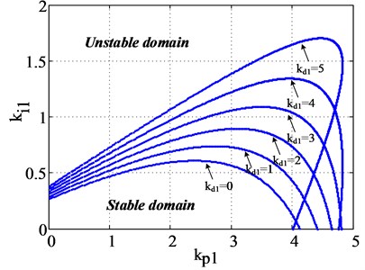
From Fig. 3, the PID parameter plane is divided into two parts by the curves of bifurcation points, i.e. stable domain and unstable domain. Specifically, the PID parameters of and can be combined freely in the stable domain. Moreover, and do not exhibit simple linear variation rules on the bifurcation line. For the area of stable domain, the larger the value, the greater the stable domain of the system. However, when 5, the stable domain is not significantly increased.
3.2. Bifurcation characteristics of the system with different time-delay
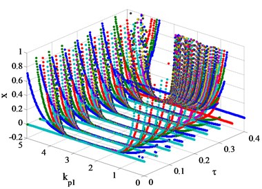
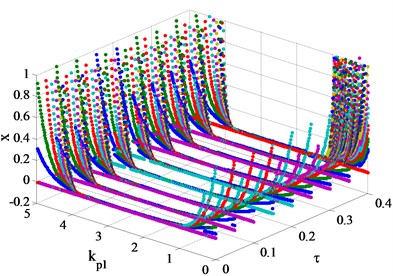
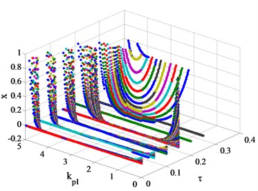
In order to study the influence of time-delay on bifurcation characteristics of the system, the following study is carried out with referring to the results of Fig. 3. The hydraulic servo system of the two units has the same time-delay and the range is 0-0.4 s, then the bifurcation diagrams of the hydro-turbine speed with different , and time-delay are shown in Fig. 4.
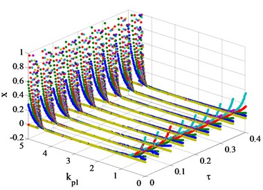
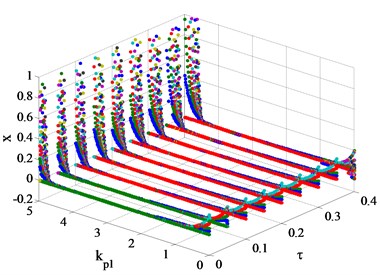
Fig. 4Bifurcation diagrams of the hydro-turbine speed xwith with different kp1, kd1 and time-delay τ values
a) 0
b) 1
c) 2
d) 3
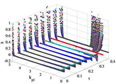
e) 4
f) 5
From Fig. 4, the bifurcation characteristics of the system can be clearly observed. Fig. 4(a) shows, when 0 and ≤ 0.3 s, the stability interval of the decreases with the increase of time-delay Specifically, when the value of is small (for example 1.2), the hydro-turbine speed x will continue to shock and cannot reach the steady state. For the larger value of (for example 1.2 < < 3.3), the hydro-turbine speed can always be stabilized at the rated speed, and the system meets the requirements of stable operation. Subsequently, there will be severe oscillation in the hydro-turbine speed as the value of is larger than its bifurcation point, which is extremely adverse for the hydropower plant and power grids. Therefore, the above unfavorable circumstance should be avoided in the actual operation of hydropower plants. It is worth noting that when time-delay > 0.3 s, no matter how to adjust the value of , the system cannot meet the requirements of stable operation.
When the values of vary from 1 to 5, the bifurcation diagrams of the system at different time-delay are shown in Fig. 4(b)-(f). It is not difficult to find that with the increase of time-delay , the bifurcation characteristics of the system are similar to that of 0. From Fig. 4(e) and Fig. 4(f), when > 0.25 s, time-delay has a significant effect on the reduction of the stability interval of . Moreover, the hydro-turbine speed is in a state of intense fluctuations and cannot reach the rated speed when 5 and > 0.25 s. It is worth noting that time-delay has little effect on the stability interval at 2 and 3.
In order to clearly and intuitively explain the variation of the stability interval in Fig. 5, and further analyze the bifurcation characteristics of the system, the bifurcation points of the system are listed in Table 2.
Fig. 5Change law of stability interval of kp1 with different kd1 and time-delay τ values
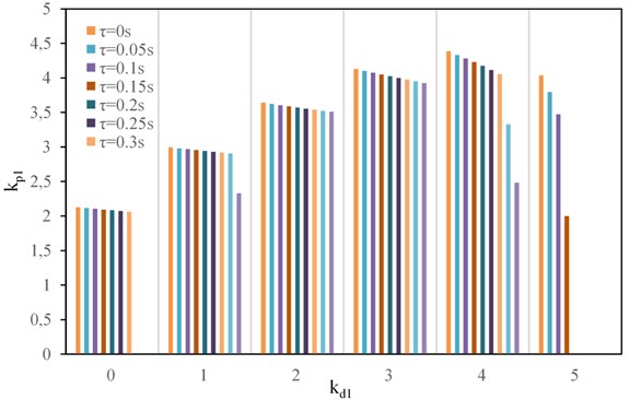
From Fig. 5, we can easily get that no matter what the value of is, the stability interval decreases with the increase of . Moreover, the stability interval increases with the increase of when 0, 1, 2, 3, 4. It is worthwhile to note that when 4 and > 0.3 s, the stability interval is greatly affected by . Furthermore, there is no stability interval when 0. For 5, the stability interval decreases rapidly with the increase of . When is greater than 0.15, there is no stability interval of , and the system cannot maintain stable operation.
From the above analysis, when 0, 1, 2, 3, 4, and the time-delay of hydraulic servo system is small (for example < 0.3 s), the larger value of is beneficial to stable operation. When is greater than 0.3 s, takes 2 or 3 is more conducive to stable operation, while 5 is not conducive to the actual operation. Hence, selecting appropriate PID parameters based on the value of is critical and the above analyses can provide some theoretical guidance for the actual operation.
Table 2The bifurcation points of the system with different τ
Time-delay | Bifurcation points | Time-delay | Bifurcation points | ||
0 s | 0 s | (1.174, 3.302) | 3 s | (0.550, 4.679) | |
0.05 s | (1.175, 3.292) | (0.550, 4.654) | |||
0.10 s | (1.176, 3.282) | (0.551, 4.628) | |||
0.15 s | (1.177, 3.272) | (0.551, 4.602) | |||
(1.178, 3.262) | (0.551, 4.577) | ||||
(1.179, 3.252) | (0.552, 4.552) | ||||
(1.180, 3.243) | (0.552, 4.528) | ||||
/ | (0.552, 4.504) | ||||
/ | (0.553, 4.480) | ||||
1 s | (0.890, 3.885) | 4 s | (0.438, 4.825) | ||
(0.891, 3.872) | (0.438, 4.773) | ||||
(0.891, 3.860) | (0.438, 4.722) | ||||
(0.892, 3.848) | (0.438, 4.668) | ||||
(0.892, 3.836) | (0.438, 4.613) | ||||
(0.893, 3.824) | (0.438, 4.555) | ||||
(0.893, 3.812) | (0.438, 4.493) | ||||
(0.894, 3.801) | (1.097, 4.425) | ||||
(1.460, 3.790) | (1.863, 4.349) | ||||
2 s | (0.698, 4.340) | 5 s | (0.340, 4.375) | ||
(0.699, 4.323) | (0.340, 4.135) | ||||
(0.699, 4.305) | (0.340, 3.814) | ||||
(0.700, 4.289) | (1.100, 3.100) | ||||
(0.700, 4.272) | / | ||||
(0.701, 4.257) | / | ||||
(0.701, 4.241) | / | ||||
(0.701, 4.226) | / | ||||
(0.701, 4.211) | / |
4. Conclusions
In this paper, considering the hydropower plant with sharing tailrace surge tank and time-delay of hydraulic servo system, a nolinear dynamic model of multi-hydro-turbine governing time-delay systems with sharing tailrace surge tank is established and its stability is analyzed. First, the stable domain of the hydro-turbine governing system is presented. Moreover, the bifurcation characteristics of the system are investigated with considering different and . When is constant, the stability interval of decreases with the increase of . When < 0.3 s and 0, 1, 2, 3, 4, the larger value of is beneficial to the stable operation. However, when > 0.3 s, takes 2 or 3 is more conducive to the stable operation. Therefore, in order to reduce the vibration of the unit in actual operations, we select the appropriate governor parameters for different time-delays.
In this paper, we assumed that the two units go through the same load disturbance during operation. For the hydropower plant with sharing tailrace surge tank, units may be influenced by stochastic disturbances with different attributes at the same time. Moreover, units may have different operating conditions, for example, one unit in the load rejection transient, another one in the sudden load increase transient. Hence, the stochastic transient stability of coupling multi-hydro-turbine will be studied in our future work.
References
-
Cheng C., Liu B., Chau K. W., Li G., Liao S. China’s small hydropower and its dispatching management. Renewable and Sustainable Energy Reviews, Vol. 42, 2015, p. 43-55.
-
Alidai A., Pothof I. W. M. Hydraulic performance of siphonic turbine in low head sites. Renewable Energy, Vol. 75, 2015, p. 505-511.
-
Westin F. F., dos Santos M. A., Martins I. D. Hydropower expansion and analysis of the use of strategic and integrated environmental assessment tools in Brazil. Renewable and Sustainable Energy Reviews, Vol. 37, 2014, p. 750-761.
-
Li X. J., Zhang J., Xu L. Y. An evaluation of ecological losses from hydropower development in Tibet. Ecological Engineering, Vol. 76, 2015, p. 178-185.
-
Ren J. Z., Gao S. Z., Tan S. Y., Dong L. C., Scipioni A. Role prioritization of hydrogen production technologies for promoting hydrogen economy in the current state of China. Renewable and Sustainable Energy Reviews, Vol. 41, 2015, p. 1217-1229.
-
Huang H. L., Yan Z. Present situation and future prospect of hydropower in China. Renewable and Sustainable Energy Reviews, Vol. 13, 2009, p. 1652-1656.
-
Xu B. B., Wang F. F., Chen D. Y., Zhang H. Hamiltonian modeling of multi-hydro-turbine governing systems with sharing common penstock and dynamic analyses under shock load. Energy Conversion and Management, Vol. 108, 2016, p. 478-487.
-
Ye F. M., Yang X. L., Wang S. R. Turbine governing and surge-tank stability. Journal of Hydraulic Research, Vol. 1, Issue 1992, 1992, p. 65-75.
-
Cai F., Cheng Y. G., Xia L. S., Jiang Y. Q. Mechanism of air-trapped vertical vortices in long-corridor-shaped surge tank of hydropower station and their elimination. Journal of Hydrodynamics, Vol. 29, Issue 5, 2017, p. 845-853.
-
Chaudry M. H. Applied Hydraulic Transients. Springer, New York, USA, 2014.
-
Dorji U., Ghomashchi R. Hydro turbine failure mechanisms: an overview. Engineering Failure Analysis, Vol. 44, 2014, p. 136-147.
-
Fang H. Q., Chen L., Shen Z. Y. Application of an improved PSO algorithm to optimal tuning of PID gains for water turbine governor. Energy Conversion and Management, Vol. 52, Issue 4, 2011, p. 1763-1770.
-
Xu B. B., Chen D. Y., Zhang H., Zhou R. Dynamic analysis and modeling of a novel fractional-order hydro-turbine-generator unit. Nonlinear Dynamics, Vol. 81, Issue 3, 2015, p. 1263-1274.
-
Shen Z. Y. Hydraulic Turbine Regulation. Hydraulic and Hydroelectricity Press, Beijing, 1998, (in Chinese).
-
Zeng Y., Zhang L. X., Guo Y. K., Qian J., Zhang C. L. The generalized Hamiltonian model for the shafting transient analysis of the hydro turbine generating sets. Nonlinear Dynamics, Vol. 76, Issue 4, 2014, p. 1921-1933.
-
Guo W. C., Yang J. D., Wang M. J., Lai X. Nonlinear modeling and stability analysis of hydro-turbine governing system with sloping ceiling tailrace tunnel under load disturbance. Energy Conversion and Management, Vol. 106, 2015, p. 127-138.
-
Nagode K., Skrjanc I. Modelling and internal fuzzy model power control of a Francis water turbine. Energies, Vol. 7, Issue 2, 2014, p. 874-889.
-
Pennacchi P., Chatterton S., Vania A. Modeling of the dynamic response of a Francis turbine. Mechanical Systems and Signal Processing, Vol. 29, 2012, p. 107-119.
-
Zhang H., Chen D. Y., Xu B. B., Wang F. F. Nonlinear modeling and dynamic analysis of hydro-turbine governing system in the process of load rejection transient. Energy Conversion and Management, Vol. 90, 2015, p. 128-137.
-
Kishor N., Singh S. P. Simulated response of NN based identification and predictive control of hydro plant. Expert Systems with Applications, Vol. 32, Issue 1, 2007, p. 233-244.
-
Wang F. F., Chen D. Y., Xu B. B., Zhang H. Nonlinear dynamics of a novel fractional-order Francis hydro-turbine governing system with time delay. Chaos Solitons and Fractals, Vol. 91, 2016, p. 329-338.
-
Xu B. B., Chen D. Y., Zhang H., Wang F. F., Zhang X. G., Wu Y. H. Hamiltonian model and dynamic analyses for a hydro-turbine governing system with fractional item and time-lag. Communications in Nonlinear Science and Numerical Simulation, Vol. 47, 2017, p. 35-47.
-
Zhang H., Hu P. Study on regulating oscillation in multi hydro turbine generators sharing flow channel structure of tailrace surge tank. Journal of Hydraulic Engineering, Vol. 46, Issue 2, 2015, p. 229-238, (in Chinese).
-
Kishor N., Saini R. P., Singh S. P. A review on hydropower plant models and control. Renewable and Sustainable Energy Reviews, Vol. 11, Issue 5, 2007, p. 776-796.
-
Demello F. P., Koessler R. J., Agee J., Taylor C. Hydraulic-turbine and turbine control-models for system dynamic studies. IEEE Transactions on Power Systems, Vol. 7, Issue 1, 1992, p. 167-179.
-
Li H. H., Chen D. Y., Zhang H., Wang F. F., Ba D. D. Nonlinear modeling and dynamic analysis of a hydro-turbine governing system in the process of sudden load increase transient. Mechanical Systems and Signal Processing, Vol. 80, 2016, p. 414-428.
-
Chen J. P., Yang J. D., Guo W. C. Bifurcation analysis of hydro-turbine regulating system with saturation nonlinearity for hydropower plant with upstream and downstream surge chambers. IOP Conference Series: Earth and Environmental Science, Vol. 49, 2016, p. 52010.
-
Specifications of Control Systems for Hydraulic Turbines. GB/T 9652.1-2007, 2007.
Cited by
About this article

This study was supported by the scientific research foundation of National Natural Science Foundation – Outstanding Youth Foundation (51622906); National Science Foundation (51479173); Fundamental Research Funds for the Central Universities (201304030577); Scientific research funds of Northwest A&F University (2013BSJJ095); the scientific research foundation on water engineering of Shaanxi Province (2013slkj-12); the Science Fund for Excellent Young Scholars from Northwest A&F University (Z109021515); and Shaanxi Nova program (2016KJXX-55).
