Abstract
Purpose of this research is to investigate the vibrations of the orthotropic plate which has Braille elements formed on its surface. Results of investigations are applied in the process of formation of Braille elements. Bending of orthotropic plate is investigated. Supplementary stiffness from the static loading in the plane stress problem caused by centrifugal forces is taken into account. Experimental investigations on a special designed experimental setup were performed. Correspondence of the experimental results with the numerical ones is determined.
1. Introduction
In recent years, in order to integrate the visually impaired people into society it is necessary to develop such forming technologies of relief elements or Braille elements which would be durable under intensive effect of vibrations. Recently by creating household or transporting equipment intended for visually impaired people, Braille was formed on various shields manufactured from plastics, metals, wood and other materials. These shields when mounted in control panels of various devices and equipment are affected by intensive vibrations. This effect takes place and is important in cars, automated wheelchairs for disabled people or household appliances.
In conventional applications of Braille usually the reader moves his finger over the surface with Braille elements. In this paper another approach is proposed: the text with Braille elements is on a circular plate performing bending vibrations on multiple eigenmodes. In this case a circular wave can be generated and some parts of the plate with Braille elements come into contact with the flat part of the human skin, while other parts loose contact with the human skin. Thus, there is no necessity to move ones finger over the text with Braille elements and reading of Braille text written circumferentially on the surface of the circular plate takes place by locating this circular plate at the flat surface of the human skin.
Different aspects of bending of orthotropic plates are investigated by many authors. The paper [1] presents the free vibration analysis of thin isotropic and anisotropic rectangular plates with various boundary conditions by using the discrete singular convolution algorithm. In paper [2] a trigonometric shear deformation theory is presented for the free vibration of thick orthotropic square and rectangular plates. In this displacement-based theory the field of in-plane displacements uses sinusoidal function in terms of thickness coordinate to include the shear deformation effect. Results obtained for frequency of bending mode, shear mode and thickness stretch mode of free vibration of simply supported orthotropic square and rectangular plates are compared with those of other refined theories and with exact solution from theory of elasticity wherever applicable. In paper [3] free vibration tests have been conducted to study the effect of low-velocity impact induced damage consisting of inter-laminar delamination accompanied by matrix cracking on the natural frequencies of thin composite laminated circular plates. In paper [4] bending of sector plates with both polar and rectilinear orthotropy is investigated using generalized differential quadrature method. Various combinations of clamped, simply supported and free boundary conditions are implemented. It is found that the present method can analyze accurately sector plates with both polar and rectilinear orthotropy. In paper [5] buckling response of orthotropic single layered graphene sheet is investigated using the nonlocal elasticity theory. In paper [6] the small deflection equation for isotropic and non-homogenous thin annular sector subject to transverse loading is derived in polar coordinates. A closed-form solution with fast convergence rate is obtained using the extended Kantorovich method and the classical theory of thin plates (Kirchhoff theory). In paper [7] the effects of the material properties, initial stress and vibration amplitude on frequency ratio of the initially stressed orthotropic plates are studied. In paper [8] the problems of natural and forced oscillations of a hinged rectangular plate with massive elliptic inclusion are studied. The numerical solution of the problem is obtained by the indirect method of boundary elements based on the sequential representation of distributions and the collocation method. The work [9] shows how the laser vibrometry crosstalk can be used for resolving the in-plane vibration component, that is the vibrations in the laser vibrometer cross direction. The result is compared to independent measurement signals from the displacement sensors. Braille dot height and other parameters describing the profile of Braille dot have significant effect to successful reading of Braille [10, 11].
Bending of orthotropic plate is investigated. Supplementary stiffness from the static loading in the plane stress problem caused by centrifugal forces is taken into account. Eigenmodes are calculated.
The numerical procedure is based on the material described in [12-15].
Experimental investigations on a special designed experimental setup were performed. Investigations for various frequencies of excitation are presented in the paper. Correspondence of the experimental results with the numerical ones is determined.
The aim of this research is to determine how the vibrations affect the plates on which the Braille has been formed and in which areas of the plate these vibrations are most dangerous.
The results of investigations are applied in the process of formation of Braille elements. The presented experimental and numerical results enable to design new types of devices with Braille elements, which have advantage in applications over the conventional Braille representations of text materials.
2. Numerical model for the analysis of bending vibrations of a rotating orthotropic structure
The numerical model has two essential features:
1) Centrifugal forces are taken into account on the basis of the method described for the general case in [15] and in this paper the method presented there is simplified for the investigated particular problem;
2) The orthotropic law is taken into account on the basis of the material presented in [14] and by assuming in the investigated problem the radial and circumferential directions of orthotrophy, this modification of taking into account of variable directions of orthotrophy is important for the proposed numerical model.
and denote the axes of coordinates. The stiffness matrix of the plane stress problem has the form:
where is the thickness of the structure and is relating the strains , , with the nodal displacements , . This matrix consists of the derivatives of the shape functions , ,…, of the two-dimensional Lagrange quadratic finite element. The transformation matrix:
where it is assumed that the directions of orthotropy coincide with the radial and angular directions of the circular structure, thus , The matrix of elastic constants for the plane stress problem:
where , are modulus of elasticity and are Poisson’s ratios and
The loading vector of centrifugal forces for the angular velocity 1 rad/s has the form , where is the density of material of the structure and is relating the displacements , with their nodal values.
By solving the static problem, the vector of nodal displacements is determined.
The stiffness matrix for the plate bending problem has the form:
where ,
The supplementary stiffness matrix has the form where , , where the stresses in the latter expression are determined from
The total stiffness matrix corresponding to rotation by the angular velocity has the form
The mass matrix has the form , where is relating the generalized displacements , , with their nodal values. Here , denote rotations around the axes and (for bending displacements , ).
3. Eigenmodes of bending vibrations of the rotating orthotropic element
The structure is a circle with internal radius 0.12 m and external radius 0.035 m. Thickness of the structure 0.0012 m. All generalized nodal displacements are assumed equal to zero on the internal radius. The following parameters are assumed: modulus of elasticity 0.34×10⁹ Pa, Poisson’s ratios 0.4 and 0.14, density of the material 1200 kg/m3.
Typical eigenmodes when 0 rad/s are presented in Fig. 1.
Typical eigenmodes when rad/s are presented in Fig. 2.
Fig. 1Eigenmodes when the structure does not rotate: a) the first, b) the second, c) the fourth eigenmode

a)

b)

c)
Fig. 2Eigenmodes when the structure rotates: a) the first, b) the second, c) the fourth eigenmode
a)

b)
c)
By comparing the eigenmodes of the rotating structure with the non-rotating one it is possible to see that for example in the first eigenmode the distances between lines of equal displacement in the non-rotating structure near to the internal radius are higher than further from the internal radius, while in the rotating structure those distances look approximately equal. This means that the bending displacement changes more uniformly in the radial direction for the rotating structure than for the non-rotating one.
Also, the structure with different orthotropic properties is investigated. The following parameters are assumed: modulus of elasticity 0.34×109·0.4/0.14 ≈ 9.71429×10⁸ Pa, Poisson’s ratios 0.14 and 0.4.
Typical eigenmodes when 0 rad/s are presented in Fig. 3.
Typical eigenmodes when rad/s are presented in Fig. 4.
By comparing the eigenmodes of the rotating structure with the non-rotating one it is possible to see that the same conclusion which was made for the previous problem with different values of physical parameters holds in this case also. But the change of the physical parameters does not have a substantial effect to the eigenmodes and thus they look similar for both cases. The performed investigations indicate that the changes of physical parameters in such problems have effect to the eigenfrequencies, but in order to notice the effect to the eigenmodes precise comparisons are to be performed.
Fig. 3Eigenmodes when the structure does not rotate: a) the first, b) the second, c) the fourth eigenmode

a)
b)

c)
Fig. 4Eigenmodes when the structure rotates: a) the first, b) the second, c) the fourth eigenmode

a)

b)

c)
4. Experimental setup for the analysis of vibrations of the element in a printing device
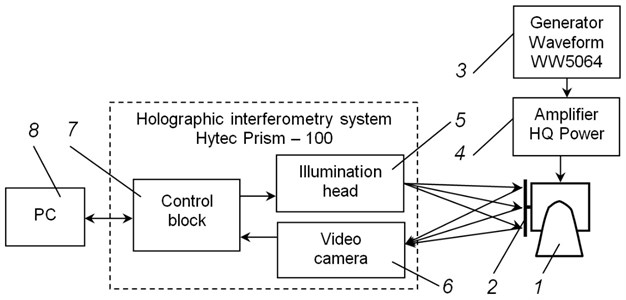
For quantitative estimation of vibrations of the orthotropic plate with Braille elements the system of holographic interferometry Hytec Prism – 100 was used. Schematic representation of the experimental setup is shown in Fig. 5.
Fig. 5Schematic representation of the experimental setup: 1 – exciter of vibrations (shaker), 2 – the investigated object, 3 – generator Waveform WW5064, 4 – amplifier HQ Power, 5 – illumination head, 6 – video camera, 7 – control block, 8 – personal computer
For qualitative estimation of vibrations of the investigated structure the vibrometer Polytec PSV – 500 was used. Schematic representation and general view of the experimental setup are presented in Fig. 6.
Fig. 6Schematic representation and general view of the experimental setup: a) schematic representation of the experimental setup: 1 – exciter of vibrations (shaker), 2 – the investigated object, 3 – scanning heads Polytec PSV – 500, 4 – vibrometer Polytec PSV – 500, 5 – personal computer; b) general view of the experimental setup; c) exciter of vibrations (shaker) and the investigated object
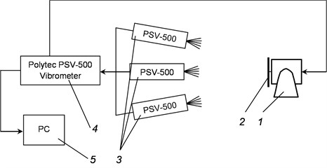
a)
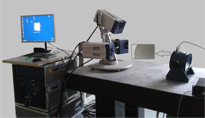
b)
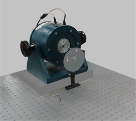
c)
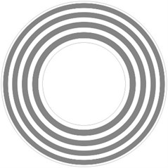
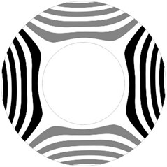
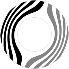
Fig. 7Results of experimental investigations using the system of holographic interferometry for various frequencies of vibration
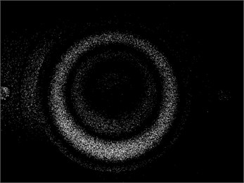
a) The first eigenmode
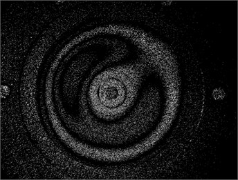
b) Linear combination of the second and the third eigenmodes
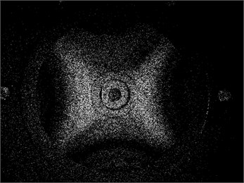
c) Linear combination of the fourth and the fifth eigenmodes
5. Results of experimental study of vibrations of the orthotropic plate
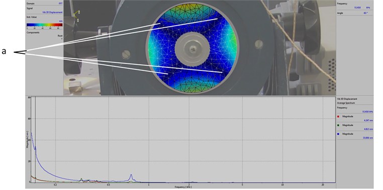
Results of quantitative investigations of vibrations of the orthotropic element for various frequencies of vibrations are presented in Fig. 7 and Fig. 8. The purpose of demonstrating and investigating these natural vibration shapes is their application in the process of design of the proposed device for reading of Braille elements written circumferentially on a circular plate.
The affecting low frequency vibrations (in the range of 140-800 Hz) have the effect to the durability of the elements of Braille formed using modern printing types. The areas of plates in which it is purposeful to form Braille elements have been determined during this research (see Fig. 8).
Further in this paper comparison of the presented results with the ones obtained numerically is performed.
6. Results of experimental investigations of vibrations of the plate with Braille elements
Braille elements have some effect to the vibrations of the plate. This effect depends on the text represented by Braille and cannot be generalized for all types of text represented on the surface of the plate. Thus, it is important to investigate the influence of Braille to the vibrations of the plate and when the effect of Braille is essential or when it could be ignored. This investigation is performed by experimental methods.
Results of experimental investigations of vibrations of a plate with Braille elements and a plate without Braille elements are presented in Fig. 9.
From the presented experimental results, it is seen that Braille elements influence the dynamic behavior of the investigated structure. For the problem with Braille elements the envelope of the amplitude of vibrations has variation of low frequency if compared with the variation of the envelope of the amplitude of vibrations of the structure without Braille elements. The system without Braille elements is symmetric and has multiple eigenmodes. Braille elements have very small effect to the dynamics of the structure, but the exact symmetry of the structure usually is destroyed. This has a very small effect to the eigenfrequencies and they become not exactly multiple, but closely spaced. When both formerly multiple eigenmodes are excited, the beatings phenomenon, which takes place when adding vibrations with closely spaced frequencies, as seen from the presented results, is observed. But this influence is more clearly seen in the investigation of transient processes taking place at definite points of the analyzed system than in the eigenmodes themselves. Thus, in the model used for investigation of the eigenmodes of the structure system without Braille elements was analyzed.
Fig. 8Results of experimental investigations of vibrations by using the vibrometer: a – recommendable areas for forming of Braille elements
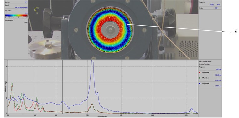
a) The first eigenmode
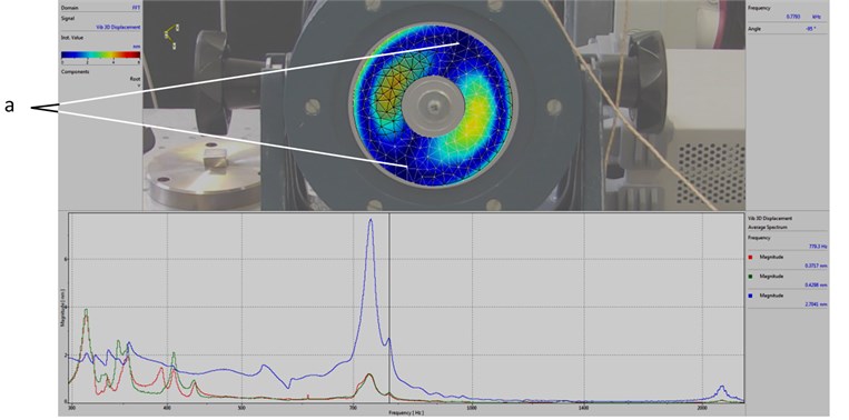
b) Linear combination of the second and the third eigenmodes
c) Linear combination of the fourth and the fifth eigenmodes
Fig. 9Results of experimental investigation of vibration in shot mode by using the vibrometer, frequency of vibrations 200 Hz
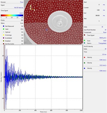
a) Plate with Braille element
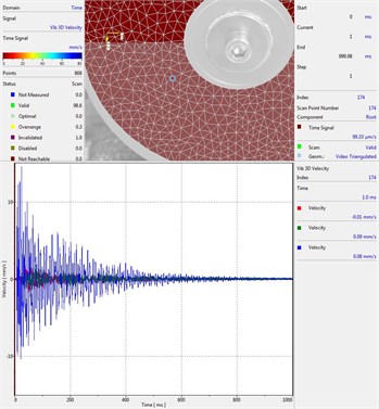
b) Plate without Braille element
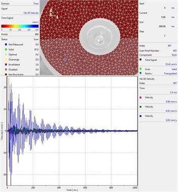
c) Plate with Braille element
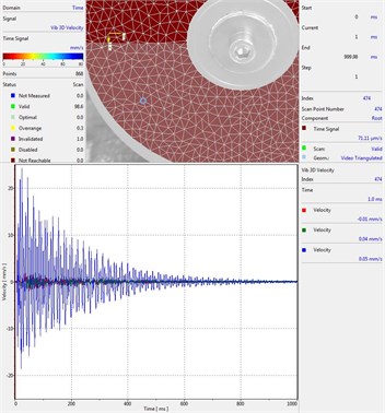
d) Plate without Braille element
7. Comparison of experimental and numerical results
Experimental investigations indicate, that the influence of Braille elements to the vibrations of the plate is not very much pronounced and it depends on the location of Braille elements. Thus, investigation of vibrations with Braille elements cannot be generalized, that is the influence of Braille elements to the vibrations of the plate depends on the text represented by Braille on the surface of the plate. Because of those reasons detailed investigations of vibrations of the plate without Braille elements were performed.
Correspondence of experimental results from Fig. 7 and Fig. 8 with the numerical results from Fig. 1, Fig. 2, Fig. 3, Fig. 4 is observed. The presented results indicate satisfactory correspondence between the experimental and numerical investigations.
8. Conclusions
Bending of orthotropic plate is investigated. Supplementary stiffness from the static loading in the plane stress problem caused by centrifugal forces is taken into account. Eigenmodes are calculated. The investigations of two problems with different physical parameters were performed.
In the first problem by comparing the eigenmodes of the rotating structure with the non-rotating one it is possible to see that for example in the first eigenmode the distances between lines of equal displacement in the non-rotating structure near to the internal radius are higher than further from the internal radius, while in the rotating structure those distances look approximately equal. This means that the bending displacement changes more uniformly in the radial direction for the rotating structure than for the non-rotating one.
In the second problem by comparing the eigenmodes of the rotating structure with the non-rotating one it is possible to see that the same conclusion which was made for the previous problem with different values of physical parameters holds in this case also. But the change of the physical parameters does not have a substantial effect to the eigenmodes and thus they look similar for both cases. The performed investigations indicate that the changes of physical parameters in such problems have effect to the eigenfrequencies, but in order to notice the effect to the eigenmodes precise comparisons are to be performed.
The results of performed research allowed to identify the areas recommended for forming of Braille elements. That is those areas in which the intensity of vibrations at least affects the durability of Braille elements.
Experimental investigations on a special designed experimental setup were performed. Investigations for various frequencies of excitation are presented in the paper. Correspondence of the experimental results with the numerical ones is determined.
References
-
Zhu Qin, Wang Xinwei Free vibration analysis of thin isotropic and anisotropic rectangular plates by the discrete singular convolution algorithm. International Journal for Numerical Methods in Engineering, Vol. 86, Issue 6, 2011, p. 782-800.
-
Ghugal Y. M., Sayyad A. S. Free vibration of thick orthotropic plates using trigonometric shear deformation theory. Latin American Journal of Solids and Structures, Vol. 8, Issue 3, 2011, p. 229-243.
-
Hou J. P., Jeronimidis G. Vibration of delaminated thin composite plates. Composites Part A – Applied Science and Manufacturing, Vol. 30, Issue 8, 1999, p. 989-995.
-
Maleki S., Tahan M. Bending analysis of laminated sector plates with polar and rectilinear orthotropy. European Journal of Mechanics A – Solids, Vol. 40, 2013, p. 84-96.
-
Farajpour A., Shahidi A. R., Mohammadi M., Mahzoon M. Buckling of orthotropic micro/nanoscale plates under linearly varying in-plane load via nonlocal continuum mechanics. Composite Structures, Vol. 94, Issue 5, 2012, p. 1605-1615.
-
Fereidoon A., Mohyeddin A., Sheikhi M., Rahmani H. Bending analysis of functionally graded annular sector plates by extended Kantorovich method. Composites Part B – Engineering, Vol. 43, Issue 5, 2012, p. 2172-2179.
-
Chen C. S. Large amplitude vibration of initially stressed orthotropic plates. Journal of Reinforced Plastics and Composites, Vol. 24, Issue 10, 2005, p. 1073-1083.
-
Sukhorolskyi M. A., Shopa T. V. Bending oscillations of a rectangular orthotropic plate with massive inclusion. Materials Science, Vol. 44, Issue 6, 2008, p. 783-791.
-
Tatar K., Gren P. Estimation of the in-plane vibrations of a rotating spindle, using out-of-plane laser vibrometry measurements. Mechanical Systems and Signal Processing, Vol. 72-73, 2016, p. 660-666.
-
Kim M. S., Young Kim I., Kyu Park Y., Ze Lee Y. The friction measurement between finger skin and material surfaces. Wear, Vol. 301, 2013, p. 338-342.
-
Childs T. H. C., Henson B. Human tactile perception of screen-printed surfaces: self-report and contact mechanics experiments. Proceedings of the Institution of Mechanical Engineers, Part J: Journal of Engineering Tribology, Vol. 221, Issue 3, 2007, p. 427-441.
-
Bathe K. J. Finite Element Procedures in Engineering Analysis. Prentice-Hall, New Jersey, 1982.
-
Zienkiewicz O. C. The Finite Element Method in Engineering Science. Mir, Moscow, 1975, (in Russian).
-
Castro J., Ostoja – Starzewski M. Elasto – plasticity of paper. International Journal of Plasticity, Vol. 19, 2003, p. 2083-2098.
-
Levy S., Wilkinson J. P. D. The Component Element Method in Dynamics with Application to Earthquake and Vehicle Engineering. McGraw-Hill, New York, 1976.
About this article

All authors declare that all of them have made contributions to the paper. So, contributions of all coauthors are acknowledged.
E. Kibirkštis developed the numerical model used for the analysis of vibrations of the investigated structure, performed the design of the experimental setup used in the investigations and took part in the interpretation of the experimental and numerical results. K. Vaitasius took part in the numerical implementation of the model used for the analysis, performed the implementation of the designed experimental setup and the interpretation of the obtained experimental results. V. Bakanauskas developed the proposed design of the experimental setup as well as took part in the implementation of this experimental setup, performed the experimental investigations and processing of the experimental results. D. Eidukynas took part in the implementation of the proposed design of the experimental setup, performed the experimental investigations and especially investigated the dynamics of the structure under impact loading. I. Venytė took part in the numerical implementation of the model used for the analysis of the structure, investigated the obtained numerical as well as experimental results and performed their mutual comparisons. K. Ragulskis proposed the numerical model used for the analysis, performed the interpretation of the numerical results and performed the comparison between the numerical and experimental results. L. Ragulskis performed the implementation of graphical output of results of calculations.
