Abstract
The type of disc brake has excellent efficiency and strong heat dissipation, which are beneficial to the transport capacity for mining motor vehicles. To ensure the reliability of the brake, the two-dimensional heat transfer differential equation model of disc brake is established, considering the dynamic change of convective heat transfer coefficient. The heat boundary conditions are established through the characteristics of brake disc structure and air condition, which is more accuracy than the traditional simplified method. Based on the PDE module in MATLAB, the mathematical model of heat transfer is solved and the transient temperature field is obtained. The calculation results are verified by the temperature field of the brake disc Link3900 NVH test platform. The results show that the research scheme has high computation accuracy, and can provide important basis, new ideas and advanced methods for the brake of mining motor vehicle in related fields.
Highlights
- Heat transfer rate in axial direction is greater than that of radial direction, which indicates that the thickness of the brake disc is more sensitive than outer diameter.
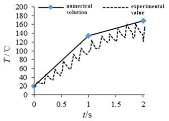
- Although the heat flow condition adopted in the analytical method is a non-discrete heat source, the numerical solution and the experimental value still show a good match in the trend and the size.
- The thickness of the brake disc is more sensitive to the temperature than that of outer diameter.
1. Introduction
The traditional type of mining motor vehicle brake is shoe-brake structure, of which contact and separation is realized through the transmission of the hand wheel linkage mechanism [1]. This type of brake mode has strong mechanical reliability and low cost, but the response time of the brake is longer, about 2-5 seconds. As a result, the braking distance of the empty travel is long, and the heat dissipation is general. What is more, it is easy to gather high temperature under continuous braking and reduce the friction coefficient of the friction pair. With the development of brake technology, research shows that hydraulic disc brake can effectively solve the shortage of shoe-brake, and is widely used in mining motor vehicle [2].
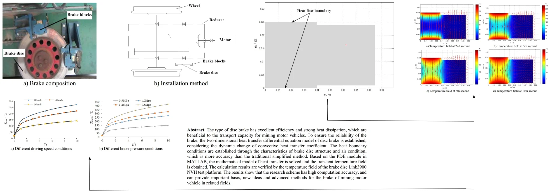
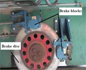
Fig. 1Schematic diagram of brake structure arrangement
a) Brake composition
b) Installation method
The disc brake of mining motor vehicle mainly consists of two components, including brake disc and brake blocks. The brake disc adopts a ventilation tray with ventilation slot structure, and the brake blocks is composed of two parts, which are arranged at 90 degrees, as shown in Fig. 1(a). In order to ensure the braking effect and reduce the impact of the braking force on gear and other components, disc brake is installed in the middle speed shaft of the reducer as shown in Fig. 1(b), and the braking torque will be delivered to the wheel spindle finally. The heat transfer characteristics of the brake are the key factors that affect the stability of the brake. At present, most of the heat transfer calculation based on analytical method simplifies the brake to one-dimensional or two-dimensional heat transfer model, neglecting the dynamic change of the heat dissipation boundary condition with the brake structure and working load [3], so the calculation accuracy is limited. Therefore, a PDE based transient heat transfer calculation method for disc brake of mining motor vehicle is presented in this paper. The influence of convective heat transfer on heat transfer characteristics is considered accurately, and the accuracy of temperature field is verified by bench test.
2. The establishment of mathematical model and boundary conditions
2.1. Heat generation condition and heat transfer equation
According to the working principle of the disc brake of the mining motor vehicle, it is known that the heat flow load produced by the brake is produced by the friction effect, and the calculation expression is as followed:
where is the heat flux in polar coordinates of at moment, unit of J/(m2·s). (0 1) is the weight of friction power and heat. is the contact area of brake blocks and brake disc, unit of m2. is the brake pressure, unit of Pa. is the rotation rate of brake disc, unit of rad/s. is the heat flow distribution coefficient.
Set the subscript 1 and 2 to express brake block and brake disc respectively, then the calculation expression of can be shown as followed:
where is thermal conductivity, unit of W/(m·K). is specific heat, unit of J/(kg·K). is density, unit of kg/m3.
The temperature field of disc brake is very small in the circumferential direction, so the heat transfer problem can be transformed to a two-dimensional transient mathematical model under the condition of cylindrical coordinate system. The non-steady state heat transfer control equation can be expressed as followed:
where is the temperature, unit of ℃. is time, unit of s.
2.2. Boundary conditions under dynamic convection heat transfer
The heat transfer of brake mainly includes three processes: heat conduction, thermal convection and thermal radiation. Under steady state, about 70 % of heat is dissipated to air through convection heat transfer [4]. It is assumed that the convective heat transfer coefficient of the two-dimensional heat transfer model of disk brake is in the radial direction, and the negative heat flux produced by the convection heat transfer can be calculated as followed:
where is negative heat flux, unit of J/(m2·s). is the main air temperature, unit of ℃.
According to the structural characteristics of the brake disc, the total convection heat transfer coefficient of of the brake disc can be divided into two parts: the end face convection heat transfer coefficient of and the ventilation slot facing heat transfer coefficient , as shown in Eq. (5). With this consideration, the solution boundary condition for Eq. (3) will be more suitable:
According to the principle of the Nusselt number calculation [5], the end face convection heat transfer coefficient of can be expressed as followed:
The ventilation slot facing heat transfer coefficient can be expressed as followed:
where the Prandt number of Pr is 0.703. is local Reynolds number, of which expression is:
where is the rotation rate of brake disc, unit of rad/s. is air density, unit of kg/m3. is characteristic length of brake disc, unit of m. is the dynamic viscosity of air, unit of Pa·s.
For the disc brake, the proportion of heat transfer caused by thermal radiation is very small, only about 5 %. Therefore, the changes in space and time can be ignored. The total negative heat flow of can be expressed as followed:
where is radiant heat transfer coefficient, unit of W/(m2·℃).
The dimension boundary range of the two-dimensional heat transfer model of the disc brake is set as and . The boundary conditions of the heat flow loading can be expressed with the second kinds of boundary conditions as followed:
The heat dissipation boundary in the axial and radial direction can be expressed with the third kinds of boundary conditions as followed:
where and are respectively local convective heat transfer coefficients at the radial both ends, unit of W/(m2·℃). and are the heat dissipation boundary of the model in the axial direction, unit of m.
3. Solution of heat transfer model based on PDE
3.1. The establishment of PDE model
In order to improve the efficiency of solving the unsteady heat transfer equation, the PDE module of MATLAB is used to deal with the partial differential equation. In the PDE module, the standard two-dimensional parabolic equation format is:
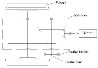
Set 1, , 0, 0 and the Eq. (12) will be translated into Eq. (3). With the boundary conditions, the temperature field of the two-dimensional model of the brake disc can be obtained.
In order to simulate the heat flow effect produced by the friction radius, the PDE model is set up as shown in Fig. 2. In the boundary condition setting, the boundary condition shown by Eq. (10) is applied to the heat flow boundary of the PDE model, and the boundary condition of Eq. (11) is applied on other boundaries. In the initial condition setting, the initial temperature is defined as 20 ℃, the driving speed is 60 km/h, the braking pressure is 1 MPa, and the total time of analysis is 10 s.
Fig. 2The two-dimensional model of PDE
3.2. Solution and analysis of heat transfer model
Through continuous iterative calculation, the two-dimensional transient temperature field of the brake disc can be obtained as shown in Fig. 3. During these cloud figures, the arrow indicates the direction of heat transfer. It can be concluded that the heat generation rate of the brake surface at the initial time is far greater than that of the continuous braking process in later stage. In the range of the friction radius, the heat transfer of the brake disc is mainly changed in axial direction slowly with the increase of the transient temperature gradient. During the change of heat transfer rate, the axial direction is greater than the radial direction, which indicates that the thickness of the brake disc is more sensitive to the temperature than that of outer diameter.
Fig. 3The two-dimensional temperature field at different moment
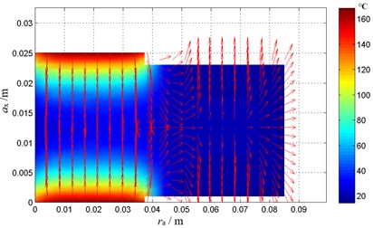
a) Temperature field at 2nd second
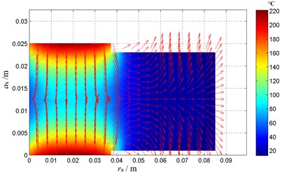
b) Temperature field at 5th second
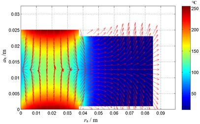
c) Temperature field at 8th second
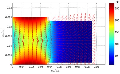
d) Temperature field at 10th second
In order to research the heat transfer characteristics of the brake disc under different braking conditions, a single variable method [5] is used to calculate the transient temperature field under different driving speed (30 km/h-60 km/h, constant brake pressure of 1 MPa) and different brake pressure (0.5 MPa-1.5 MPa, constant driving speed of 60 km/h).
The peak temperature of the calculated results is extracted, and the peak temperature variation curves under different braking conditions are shown as in Fig. 4.
Fig. 4Temperature peak variation curve under different conditions
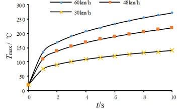
a) Different driving speed conditions
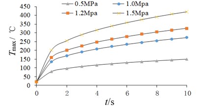
b) Different brake pressure conditions
From Fig. 4(a), it can be seen that the temperature peak increases with the increase of the driving speed. In other words, the higher the driving speed is, the greater the heating rate of the disc brake is, the longer the time it takes for the transient temperature to move to the dynamic balance. Under the influence of the material of the brake disc, the temperature peak at different speed increases sharply in the 0-1 s time, and then tends to slow. Because of the effect of the brake disc material, the temperature peaks at different speeds increase sharply in the 0-1 s time, and then tend to slow down.
From Fig. 4(b), it can be known that the effect of different braking pressure on the change of temperature peak is similar to that of driving speed. But according to the specific data analysis, pressure is more sensitive to the change of brake disc temperature peak value. The change rate of temperature peak value almost synchronizes with time under different brake pressure and driving speed. It shows that the change of temperature peak caused by the interaction of heat generation rate and heat transfer rate is quite little affected by load condition.
4. Test verification
4.1. Type of test and installation
In order to verify the feasibility and accuracy of the disc brake temperature field calculation results, the bench test research that used for transport engineering is introduced [6]. The Link3900 NVH test bench is chosen to simulate the various braking conditions in the paper, which is able to complete the test of the transient temperature for the brake disc. The test bench is currently the most advanced thermodynamic testing equipment that used for the friction characteristics research of disc brake. It belongs to inertial platform test machine, which can simulate the load and driving state. Through the program, the environment temperature, air velocity, air temperature, brake pressure, brake disc speed and other parameters can be controlled [7].
In the experimental research, the installation structure of the brake and sensor is designed as shown in Fig. 5. The brake disc is connected with the spindle of the test platform through a universal coupling, of which the speed is controlled by the computer. The built-in sensor of the test bench includes torque speed sensor, displacement sensor and so on. The external sensor (temperature sensor) that selected in this test is the high-precision micro thermocouple, of which thermal response time of the sensor is less than 0.01 s. When the temperature sensor is installed, the ventilation groove on the end of the brake disc needs to be perforated. The lead wire can directly connect to the information acquisition system.
4.2. Condition setting and result analysis
In order to ensure the reliability of the test results, the plane degree detection of the end face should be completed before the installation of the brake disc, so as to avoid the interference of the machining error to the test data. In the test, the brake pressure is set as 1 MPa, the spindle speed is set as 46.4 rad/s, and the initial temperature is set as 20 ℃. The single test cycle of continuous braking should be set up, which needs a longer time interval to ensure that the initial state of the test is exactly the same. Every test cycle for braking is carried out, and the average value of the temperature that is corresponding to the time step are taken as final results.
According to the change curve of temperature peak as shown in Fig. 4, the peak value at the 1st second moment and 2nd second moment is taken as the contrast data. The verification result of transient temperature between numerical solution and experimental value is obtained, as shown in Fig. 6. It can be seen that although the heat flow condition adopted in the analytical method is a non-discrete heat source, the numerical solution and the experimental value still show a good match in the trend and the size. It can be concluded that the analytical research method has good feasibility and high calculation precision for the heat transfer characteristics calculation of the mining motor vehicle disc brake.
Fig. 5The installation sketch of bench test
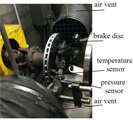
Fig. 6Verification of results
5. Conclusions
According to the long downhill uniform braking condition of the mining motor vehicle, the calculation of two-dimensional transient temperature field can be realized by using the analytic method efficiently and accurately, of which load and constraint are respectively expressed by the second and third boundary conditions, fully considering the heat transfer influence of brake disc structure and air flow characteristics. During the results of heat transfer calculation, it can be known that heat transfer rate in axial direction is greater than that of radial direction, which indicates that the thickness of the brake disc is more sensitive than outer diameter. The experimental research shows that the analytical research method in the paper has good feasibility and high calculation precision, which can provide important basis for structural optimization research.
References
-
Xiangzhou Q., Haixin T. Research on transportation brake system based on coal mine motor vehicle. Engineering Technology, Vol. 44, Issue 5, 2016, p. 317-318.
-
Xiandong L., Zengjie R. Test and analysis of friction characteristics and brake scream of disc brake. Vibration Test and Diagnosis, Vol. 33, Issue 5, 2013, p. 746-750.
-
Chenghui G., Xiezhao L. The influence of braking condition parameters on the distribution of friction temperature field of brake disc. Journal of Engineering Design, Vol. 13, Issue 1, 2006, p. 44-48.
-
Rainieri S., Bozzoli F., Pagliarini G. Experimental investigation on the convective heat transfer in straight and coiled corrugated tubes for highly viscous fluids. International Journal of Heat and Mass Transfer, Vol. 55, Issue 3, 2012, p. 498-504.
-
Zhili S., Ming Y., Guoquan L. Discussion on the calculation model of convection heat transfer coefficient of vertical wall. Journal of Northeastern University, Vol. 26, Issue 5, 2005, p. 484-487.
-
Huanling L., Jianyuan J., Lei Y. Effect of axial heat conduction and inlet effect on convective heat transfer characteristics of circular microchannel. Journal of Xidian University, Vol. 35, 5, p. 916-921.
-
Daxin L., Lining W., Jun H. Research on selection of testing equipment for automobile friction materials. Journal of Test Technology, Vol. 29, Issue 3, 2017, p. 43-46.
About this article

