Abstract
The article examines the work and key elements of the automated system for supplying abrasive material using a managed pneumatic dispensing. Proposed to manage the flow of abrasive material using continuous (for the case of emergency braking) and pulse form of dosing. Using the pulse form that allows dosing of abrasive material in a wide range, providing a number of additional options to control the sand system. Developed a functional diagram of the automatic flow of abrasive material supply system, which provides control over the flow of abrasive material and its comparison with the reference case, according to the gradation performance of the system (algorithm of dosing). The main elements of the developed system are analyzed.
1. Introduction
The quality of services in the market of railway passenger transportation is determined by such parameters as rate and time of delivery, the safety and security of passengers and cargo, trains movement on their schedule, technical and economic indicators of work of railways, etc.
The combination of these factors is crucial for the formation of volume, cost and quality of passenger and freight rail transportation. Several factors influence the level of these indicators, such as speed, traffic safety, which is mainly determined by the interaction in the system “wheel-rail”, which is the basis of the movement of trains.
Currently ways of managing the interaction (coupling) in the system “wheel-rail” for existing and future conditions are developing [1-3]. The operation of the cohesion based on the concept of influence on friction surfaces of the contact of the wheels with the rails, creating a surface with desired friction characteristics. The most popular way is to supply on the surfaces of friction of various abrasive materials, which, together with the “third body” create surface layers having the desired frictional properties [4, 5].
Abrasive material (sand) that is applied to improve the grip, has not only a positive impact, but at excessive contaminate the supply track structure, increases the wear of wheelset, increases the resistance to movement of the whole and the whole train [6, 7]. To avoid this, the amount of sand in contact should be strictly regulated. From the point of view of thrust, the best result is achieved when applying sand in a single layer with the distance between the grains bounds equal to three grains of sand (saturated fill the contact is 0,06 kg/m2 [7-9]). Thus, the amount of sand applied per linear meter of rail on the raceway width of 10 mm should be equal to 0,6 g/m.
As is known the usage of sand for increasing the coupling forces requires huge expenses. Millions of tons of sand need to be produced, transport and special technology to process before it enters the sand bunker system of the locomotive. Annually to improve the interaction of wheels and rails on the railway network more than three million cubic meters of sand are spent. On average one kilometer of rail track there is more than 20 tons of spent sand [7-9].
The analysis of experimental studies and the results of calculations show (Fig. 1), that in operation at speeds up to 40 km/h even when the performance of the sandbox in real operation conditions up to 1 kg/min, there is a significant waste of sand. This leads to the contamination of rail-sleeper grid and a waste of sand.
Fig. 1The dependence of the amount of sand n, supplied in one meter of rail from speed V=10–100 km/h (P= 0,4–1 kg/min) [8-10]
![The dependence of the amount of sand n, supplied in one meter of rail from speed V=10–100 km/h (P= 0,4–1 kg/min) [8-10]](https://static-01.extrica.com/articles/19922/19922-img1.jpg)
Analysis of methods for conveying various bulk materials in the zone of contact of wheel and rail, suggests that the general trend – with the help of various additional devices to adjust their performance to achieve a more uniform flow of material or a certain quantity to realize the maximum possible contact in the “wheel-rail” system [11, 12].
There is currently no system of automatic control and optimization of parameters of pneumoconiosis devices that could provide not only sustainable mode of supplying and dosing of abrasive granular material. Therefore, it is necessary to develop a method of automatic control of the process in the most efficient and cost-effective dosing of abrasive material, adaptable to various weather conditions and modes of movement of the locomotive.
2. Design of the supplying system
The flow of the abrasive material can be implemented both in continuous and in pulsed form. Using a pulsed form, you can perform the dosing of abrasive material in a wide range, providing a number of additional features to control the supplying system:
– Management in the form of strictly regulated weight or bulk doses of abrasive material increases the accuracy of the average flow rate,
– The presence on the governing influence of signals with different amplitude, cycle duration and duty, which allows to improve the quality of dosing,
– Constant instant flow within a single pulse can be stabilized at the value that best suits the requirements of a specific use,
– Parameters of two-phase flow at a constant flow rate can be determined by calculation, making it easy to adjust and configure the system.
When supplying material in the form of a pulse sequence with constant parameters of the pulses and the variable frequency of their submission, the average time volumetric flow rate of the material is determined by formula:
where: – the volume of a single dose, – frequency of doses issue, – issue period.
When applying the pulse parameters of the pulse sequence must be chosen so that the time interval between pulses at maximum frequency allowed for some margin of time to fill the surface of the porous plate of the dispenser. When designing a system, it is necessary to solve two main tasks – to define the parameters of the pulse flow (amplitude, duration and duty factor) and calculation of the main structural parameters of the executing device.
The supply system of abrasive material works in two modes supply – continuous (for the case of emergency braking) and pulse. Such a system should provide sufficient performance and the accuracy of controlling the flow of material.
Functional diagram of the system of automatic regulation of flow of abrasive material is presented in Fig. 2. The scheme provides control over the flow of abrasive material and its comparison with the reference case (according to the gradation performance) [13].
Fig. 2Functional diagram of a system for automatic regulation of flow of abrasive material
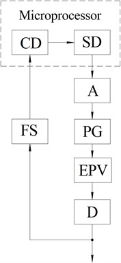
The main elements of the system are the microprocessor, which includes a setting device (SD) and comparative device (CD) and the amplifier (A), pulse generator (PG), electro-pneumatic regulator (EPV), the dispenser (D) and the flow sensor of abrasive material (AM).
Software of setting device, processed by the microprocessor, receives the setting signal from the operator with the remote control and transmits them to the amplifier. Therefore, the microprocessor is one of the most important elements of the supply system of abrasive material. For correct operation of the system does not require a high-performance microprocessor, the main thing is to have enough resources to run the software and process the information received from the flow sensor.
The amplifier is selected based on the matching (gain) of the input signal (voltage) coming from the microprocessor to a level sufficient to trigger the pulse generator and electro-pneumatic regulator. The pulse generator provides the ability to adjust the frequency, duration and duty cycle of the pulses and pulses of different forms.
Electro pneumatic valves are used to control the pneumatic system in continuous or pulse of compressed air to the dispenser, while accelerating the flow of abrasive material.
The inclusion of a supply system of abrasive material is chosen by the operator of one of the performance grades of sand system on the remote control (depending on weather conditions and the mode of movement of the train). The setting signal for controlling the flow supplied to the microprocessor on the amplifier. Next, the amplified signal is supplied to the pulse generator, which produces pulses of a certain form, duration, and duty cycle affecting the operation of fast-acting electro-pneumatic valve connected to the source of compressed air. A source of compressed air is a pneumatic system of the locomotive or specially mounted compressor with air pressure of 0,4 MPa to 1,0 MPa.
As a metering pump pulse (discrete) of the dispenser is used (Fig. 3), not having a complex structure, easy to maintain, allows supplying of the dosing material as continuous, and pulsed at certain intervals of time [13].
The supply rate of the material is determined by the structural characteristics of the dispenser and can be adjusted in the selected range according to the gradation performance of the system.
The principle of operation of the dispenser based on a property of bulk materials to acquire the properties of the liquid at the air supply for aeration. In the initial state supplied abrasive material is in the hopper. Abrasive material from the hopper flows out on a porous plate, however, does not move further, because the force of friction of abrasive particles to each other and the porous plate prevents the force of gravity to propel the particles and push them through the outlet of the dispenser. Thus, due to no compressed air supply material self-keeping takes place.
When compressed air inlet, the air passes through the porous plate and aerates the material layer adjacent to the plate. In this case, the layer of material takes the role of a lubricant, the friction force of the particles decreases and becomes less than the force of gravity, which pushes the material through the outlet. Air for aeration is supplied through the electro pneumatic valve. The value of a pulse of air for aeration is determined by the control device according to the grading system (dosing algorithm). The velocity of the abrasive material depends on the material properties (particle size, particle shape, moisture content), the design of the spout and the intensity of the air stream that is directed to aeration.
The advantages of this dispenser are:
– Pulse and the continuous supply method, which is very important in emergency braking when you need to file a uniform flow,
– A large range of changes in the magnitude of the dose of the supply material,
– Simple design: the dispenser has no moving parts, no lubrication, no wear, is compact and inexpensive to manufacture and maintain,
– Low pressure air necessary for aeration,
– Low consumption of compressed air required for operation of the dispenser.
Fig. 3Dispenser with hopper for abrasive material: 1 – hopper with abrasive material, 2 – compressed air supplying tube, 3 – porous plate, 4 – the two-phase flow outlet nozzle
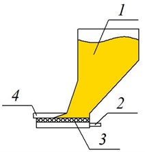
a) Without compressed air
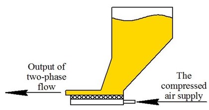
b) When applying compressed air
On the performance of a sand system is affected by such factors as abrasive material humidity, sand blockage of pipelines, the leakage of the pneumatic system and connective piping. As the movement of two-phase flow has its own characteristics associated with the different dispersion of the abrasive composition, the difference in velocities of the individual phases and their concentration. Taking these factors into account, and especially when the abrasive is necessary to have an accurate idea of the magnitude of the flow that will allow us to monitor and adjust the performance of the system in operation.
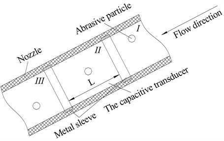
Based on the analysis of the flow of bulk materials and experience of scientists who conducted research in this area [14, 15], the development of the flow sensor of an abrasive material selected capacitive transducer, which responds to the measurement of the coefficient of filling of the abrasive material with the dielectric permittivity. This sensor can be used as an indicator of the concentration of abrasive material in the working area of the measuring capacitor. The flow sensor consists of a rubber nozzle, which is coaxially installed two metal sleeves with an internal diameter equal to the diameter of the nozzle (Fig. 4). Bushings are the electrodes of the capacitor connected to the power source.
Fig. 4The scheme of movement of the abrasive particles in the nozzle using capacitive transducer
During the movement through the condenser two-phase abrasive flow is considered as a double-layer capacitor with dielectric. The capacitance of this capacitor is determined by the formula [14]:
where: – dielectric constant, – the area of the capacitor electrode, – the distance between the electrodes of the capacitor occupied abrasive material with a dielectric constant , – the distance between the electrodes of the capacitor occupied by an air gap.
Since the abrasive particles have a shape close to a sphere with radius and move randomly throughout the volume of the measuring capacitor, consider a two-phase abrasive stream in the form of a double-layer dielectric by volume (volume of the working area of the capacitor occupied by air) and (volume of the working area of the capacitor occupied abrasive material). Provided that in the capacitive transducer contains number of particles of abrasive material can be calculated using formula:
If a known volume of a solid substance, at a predetermined area of the electrodes of the capacitive transducer can determine the magnitude of the dielectric layer:
Substituting the Eq. (4) into (2) we obtain a relation between the capacitance of the capacitive transmitter with the concentration of abrasive material in the sensor. For determining the flow of abrasive material is necessary to find the velocity of the particles in the stream by setting the rate of change of capacitance of the measuring capacitor.
With the passage of two-phase flow through an electric field occurs the phenomenon of polarization, contributing to the capacitance change .
The movement of the abrasive material in the nozzle with integrated capacitive transducer can be considered in three stages (Fig. 5):
• Stage I – before the advent of the abrasive particles in the electric field of the capacitive transducer, and its capacity is equal to ,
• Stage II – the abrasive particle is located between the electrodes of the transducer, the capacitance of the capacitive transducer is equal to ,
• Stage III – abrasive particle is outside the electric field of the capacitive transducer, the capacitance of the capacitive transducer is equal to .
For measuring the speed of movement of the solids is required to fix the period of time in which the capacity of the Converter will be different from the capacity . The time measurement of the movement of the abrasive material in the capacitive transducer allows to determine the speed of its movement :
where: – length of the electrodes of the capacitive transducer, – time of movement of the abrasive particles in the capacitive transducer.
The movement of the abrasive material through the nozzle affects the capacitance of the capacitor, which changes in proportion to the dielectric permittivity of the material and its volume. The change in the electrical capacitance of the capacitor will be manifested in his charge, held on the electrodes, since it is connected to DC voltage source:
The amount of change of charge is directly proportional to the change in the electrical capacitance of the capacitor and fed to the voltage electrodes. The capacitance change is directly related to dielectric constant abrasive material, its volume and the geometric location of the electric field inside the capacitor. The change of the charge of the capacitor forms a polarization voltage:
Moving each of the abrasive particles through the electric field of the capacitor, the particle will create a surge of electric current (Fig. 5), the maximum value of which is determined not only by the geometrical and electrical characteristics of the material but also the speed of its movement. The faster the particle is, the greater will be the current pulse.
Fig. 5The value of the electric current the measuring capacitor when driving through it abrasive material of different concentrations
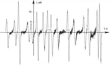
a) Low concentration
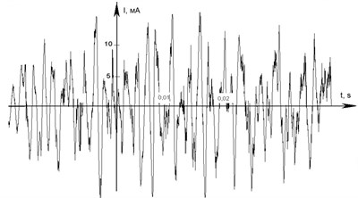
b) Average concentration
The received signal through the amplifier is fed to the Comparators of analog signals for fixing the polarization currents caused by movement of the abrasive material. The outputs of the Comparators are connected to the microcontroller for determining the time interval between the signals from the Comparators. A microcontroller for a given program calculates the speed of each particle and gives the average flow rate of particles over a certain period of time. The measured speed of movement of the abrasive material and its concentration in the capacitive transducer served as input data to calculate the mass and volume flow.
The flow rate is transmitted in a comparative microprocessor device that allows you to compare the flow rate during operation with calibration dependence corresponding to the gradation performance of the supply system of abrasive material. The results of this comparison can determine the problem is the blockage of pipes, leakage, lack of abrasive material in the hopper, the failure of the pneumatic system, etc. [15].
In case of blockage of the nozzle, its dielectric constant will be much higher than during the passage through it of a stream of abrasive material and the signal of the microcontroller, will be of the highest value, which indicates the formation of a “tube” in the nozzle. Thus, the use of the device with the flow of abrasive material allows you to manage the performance and monitor the flow of material during the movement of the locomotive and to determine the system performance in different conditions.
3. Conclusions
(1) Developed supply system of abrasive material complies with existing analogues in the world on key indicators.
(2) Its automation and the use of a managed abrasive material allows you to control and adjust the performance of the abrasive material in a given range, to obtain linearity of the dependency control signal – output material flow, calculate, adjust and control the metering characteristic in the operation.
References
-
Gorbunov N., Kovtanets M., Kravchenko K., Boyko G., Chernysheva Y., Gorbunov N. Sand System of the Locomotive. Patent of Ukraine No. 80637 for Utility Model, Bulletin No. 11, 2013.
-
Hauser V., Nozhenko O. S., Kravchenko K. O., Loulová M., Gerlici J., Lack T. Proposal of a mechanism for setting bogie wheelsets to radial position while riding along track curve. Manufacturing Technology, Vol. 17, Issue 2, 2017, p. 186-192.
-
Mogila V., Vasyliev I., Nozhenko E. The use of biofuel on the railway transport. Transport Problems, Vol. 7, Issue 1, 2012, p. 21-26.
-
Kovtanets M., Kravchenko K., Gorbunov N., Boyko G. Application of Expert Evaluation for Adoption of Technical Solutions. Science news of Dahl University, Vol. 7, 2012.
-
Kovtanets M., Gorbunov N., Prosvirova O., Sosnovenko S., Astakhov V. Increase of coupling characteristics and profitability of the locomotive modernization of system of supply of sand. ТЕKА, Commission of Motorization and Power Industry in Agriculture, Vol. 12, Issue 4, 2013, p. 90-96.
-
Gorbunov N., Kovtanets M., Slaschev V., Kravchenko K., Prosvirova O. Adaptive supply of sand. Journal of Volodymyr Dahl East Ukrainian National University, Vol. 5, Issue 1, 2012, p. 108-112.
-
Osenin J., Marchenko D., Shvedchikova I. Frictional Interaction Wheel and Rail. Volodymyr Dahl East Ukrainian National University, Lugansk, 1997.
-
Kravchenko K. The Grounds of Increase Backlogs of Locomotive Hauling Qualities and Its Realization by the Management of Sliding in the System of Wheel with a Rail. Volodymyr Dahl East Ukrainian National University, Lugansk, 2010.
-
Gorbunov N., Kostyukevich A., Kravchenko K. Еfficiency function for evaluation of the locomotive traction and adhesion qualities. ТЕKА. Commission of Motorization and Power Industry in Agriculture, Vol. 10, Issue 10, 2010, p. 80-86.
-
Kovtanets M., Naysh N., Kravchenko K., Kara S. Improved method of operating a sand system of the locomotive in the diverters. Journal of Volodymyr Dahl East Ukrainian National University, Vol. 4, Issue 1, 2011, p. 74-78.
-
Kostyukevich A.,Gorbunov N., Kovtanets M. Experimental verification of the effectiveness of the jet-abrasive action on the rails to improve the frictional properties of the contact “wheel-rail”. Journal of Volodymyr Dahl East Ukrainian National University, Vol. 18, Issue 1, 2013, p. 33-37.
-
Gorbunov N., Kovtanets M., Prosvirova O., Garkushin E. Adhesion control in the system of “wheel-rail”. Transport Problems, Vol. 7, Issue 3, 2012, p. 15-24.
-
Gorbunov N., Kovtanets M., Nozhenko O., Nozhenko V.,Prosvirova O., Chernikov V. Automated abrasive material supplying system with controlled pneumatic dispensing. Journal of Volodymyr Dahl East Ukrainian National University, Vol. 1, 2015, p. 230-235.
-
Afonin V. S. Measuring the flow of particulate material based on the capacitive transducer. Polzunovsky Bulletin, No. 2/2, 2011, p. 43-48.
-
Gorbunov N., Mikhailov E., Kashura A., Golubenko A., Kudla P., Mogila V., Osenin J. Sandbox of the Locomotive. Patent of USSR No. 1781112А1, Bulletin No. 46, 1992.
About this article

The research was held on the basis of the scientific research “Creating a multi-functional high-end energy management engineering contact surfaces ‘wheel-rail’ for eco-efficient power transmission”, funded by the Ministry of Education and Science of Ukraine and an output of the internal BUT research Project Reg. No. FSI-S-17-4104.
