Abstract
Blasting works cause short-term high-energy shock waves - acoustic, air (airblast) and paraseismic. The duration of the event can be up to 2-3 seconds, while the rise time to the peak value is directly related to the delay between the individual explosive material (EM) and the firing sequence and ranges from a few to several milliseconds. Their propagation in the environment can affect people, animals and construction structures located not only in the close but also further distance from their source. If EM is placed on the surface of the earth during the detonation, the shock wave spreads evenly in all directions in the half-space, and when the detonation follows in rock, the wave usually travels in one direction and is accompanied by a paraseismic wave. However, the sound heard when detonating is part of the wave spectrum in the band from 20 to 20000 Hz, while the airblast itself has a frequency of less than 20 Hz. Since at some distance from the detonated EM, the parameters of the airblast are close to the parameters of the acoustic wave, the method of spreading the acoustic wave depends to a great extent on atmospheric conditions, i.e. density, temperature and humidity of the air, and from wind speed and its direction. To get to know the essence of the phenomenon of the impact of blasting works, measurements are carried out considering the propagation conditions, i.e. meteorological conditions as well as vibration analysis in the ground itself and on the building substructure. This paper presents the results of research carried out by the Authors in terms of the correct assessment of the impact range (acoustic, airblast, paraseismic waves) during EM detonation placed on the surface.
1. Introduction
There are various side effects of a detonation of explosive materials (EM), i.e.: excited vibrations, airblast (AB), acoustic wave (AW), scattering, gunshots, dust and many others depending on the specificity of the work using EM. Vibrations, AB and AW may overlap since as a physical phenomenon they are waves which are spreading in various centers (ground, water, air) at different speeds. The coexistence of these interactions may cause change in the intensity of the occurrence of another impact and reduce the effectiveness of the prevention of other impacts. Impacts that are in mutual interaction can therefore be referred to as combined effects. This phenomenon occurs especially when the EM loads are detonated on the surface or under a small shield, i.e. in engineering works (e.g. cladding, destruction works using cumulative charges, etc.).
The issue of the impact of vibrations induced by the detonation of EM on the environment is widely discussed around the world. More and more new analytical methods [1] and numerical modelling [2-5] techniques are used to accurately predict the intensity of vibrations at a given point and the way they are transferred to building objects. Similarly, research on the impact of AB is focused on interaction in close proximity to detonation place and is carried out for military purposes. The problem of the coexistence of the impact of these threats was discussed, among others in the papers [6-10] where attention was paid to disturbing the seismic signal with other signals. While in the works [8, 11, 12] the problem of the impact of AB on vibration meters was noticed, in papers [6, 7, 9, 10] the impact of the acoustic wave on geophones and the way of their unambiguous identification and elimination was done. One of the first studies related to acoustic aspects of the impact of blasting works in mine was [13]. However, the study of noise levels (AW) emitted by blasting works was the subject of research in Poland [14]. In this work the problem of the accuracy of the assessment of its distribution at a further distance from the blasting works performed in the opencast mine and the military range was discussed on the example of measurements of high-energy impulse noise. The attention was focused on the uncertainty of the measurements carried out in the aspect of assessing the impact on the acoustic climate.
In this paper, the Authors presented results of comprehensive tests of selected semi-physical (i.e. airblast, acoustic wave, paraseismic and building structure vibrations) from high-energy pulses (blasting works) in the aspect of environmental impact, in particular, buildings and human.
Measurements (AW) were made in accordance with the methodology set out in Annex 8 to the Regulation of the Minister of Environment dated 30 October 2014 [15], including the definitions contained in ISO 1996-2:2017 [16] and other thematically related documents [17, 18]. The assessment of the impact of vibrations transmitted through the ground on buildings was carried out in accordance with the guidelines of PN-B-02170:2016-12 [19] as well as other applicable in the world (DIN 4150, EUROCODE 8) [20-22] means that these standards cannot be used to assess the impact of vibrations induced by AB on protected objects. Since the seismic signal may be disturbed by the acoustic wave and AB, there is a risk that over-interpretation of recorded signals and errors in the assessment of the impact of vibrations on the environment may occur.
2. Threats as a physical phenomenon
Structural vibrations, airblast and acoustic wave are mechanical waves, so they propagate in elastic medium. When the elastic vibrations of its particles arise under the influence of a single applied force in the studied medium, it can be assumed that in this environment a spring wave running with finite velocity is created. Then every particle derived from the equilibrium position after the cause of the disruption ceases to begin to return to it, a simple vibrational movement with the acceleration turned towards this point.
Particle velocity is equal zero at its maximum deflection, and reaches its highest value when passing through the equilibrium point. The type of rough acoustic wave depends on the nature of the pressure changes. If the pressure changes in a sinusoidal way, the resulting wave is called the harmonic wave. Changes of instantaneous harmonic amplitude values are described by the function:
where: – maximum amplitude, – initial phase of motion, – time counted from the moment when the vibrating point has an amplitude of zero, – angular velocity, – vibration period 2/, assuming that 0, 0, .
The first derivative from Eq. (1) gives us the velocity of vibratory motion , and the second its acceleration .
A low amplitude disturbance induced in air which density and pressure are everywhere uniform, spreads in all directions from the source at the speed of sound. This is the so-called acoustic wave (AW). Sound effects are not always present because they depend on frequency [14]. The acoustic wave is an adiabatic wave and it decays due to the viscosity of the environment and the dissipation of heat. The speed of movement of the gas particles is consistent with the direction of the wave propagation, so it is a longitudinal wave with a constant velocity.
In the case of a disturbance with a large amplitude, a gas compression stroke (a thin layer of air) is created which propagates faster than sound, called the airblast (AB). These gases spread from the center of the explosion, in the form of waves of high temperature, density, and pressure. Behind the head of the shockwave, gas products expand, bringing a gentle drop in their pressure. As a result, this leads to a reduction in their gas velocity. This decrease is caused by the unloading wave (rarefaction) that moves just after the shockwave [23]. At some distance from the source of the detonation, the speed of the gunshots drops to zero, and the airblast (AB) spreads further as a result of inertia forces. Then the pressure of the shockwave reaches the atmospheric pressure and the speed of the wave - the speed of the sound. Airblast goes on as an acoustic wave [14]. In the air, the passage of an intense shockwave at a short distance from the source is accompanied by the formation of a characteristic mist due to the condensation of water vapor, it is called Prandtl-Glauert’s cloud.
3. Characteristic of outdoor research
The research was conducted in the vicinity of one of the largest military training grounds in Poland in the urbanized area. The subject of the discussion was the range of impact of explosive charges induced during detonation i.e. structural vibrations, airblast (AB) and acoustic wave (AW).
During the measurements, three series of explosive material (ANFO type) were fired, with masses: series I – 150 kg, series II – 300 kg and series III – 450 kg. In all cases, the EM loads were launched on the surface.
Measurements were made simultaneously on two points (village), located at the nearest objects in the direction of propagation. Full sets of equipment for measuring ground and object vibration intensity, airblast pressure and noise level (acoustic wave) were used at each station. Distance from the blasting place to the measuring point No. 1 (Town 1): approx. 7.5 km, to the measuring point No. 2 (Town 2): approx. 6.5 km.
For the measurement of noise levels (acoustic wave), two digital SVAN 958 sound and vibration meters from SVANTEK company were used, equipped with 1/2” free-field microphones type 40AE from G.R.A.S. company. Sound measurement was performed in 1st accuracy class. The measurement consistency was ensured by the acoustic calibration SV30A from SVANTEK with reference sound source with a level of 113.9 dB. The UVS 1608 and VIBRALOC from the Swedish company Nitro Consult AB equipped with UVS airblast microphones, which meet the requirements of PN-B-02170: 2016-12, was used to study the vibration intensity and air pressure of the shockwave.
The measurements were made during cloudy but rainless weather. The basic parameters of weather conditions on the day of the measurement (between 11:00 and 13:00) are given below:
Temperature: 6°C, Humidity: 81 %, Pressure: 1022 HPa, Wind: variable from 0 to 2 m/s, SW direction.
Measurements were made in weather conditions favoring good propagation of sound in the air, i.e. lack of vegetation (leaves), low-level of clouds, no rain. Therefore, there were unfavorable conditions from the point of view of their impact on the perceived vibroacoustic nuisance.
4. Research methodology
Due to the fact that measurements were made in Poland, experimental tests were carried out in accordance with the following guidelines:
In the field of vibration measurement – Polish standard PN-B-02170: 2016-12 [19]. The standard specifies the location and method of mounting sensors for vibration measurements and the minimum technical parameters of vibration sensors. In the assessment using dynamic impacts (SWD I and SWD II), seismograms (full waveforms) of horizontal vibration components should be used, i.e. in and directions recorded at point placed from side of vibration source, at the rigid structure node - at the intersection of load-bearing walls in two directions – located on the substructure of the building or in a rigid node on the wall of the underground storey in the level of the surrounding area. The seismograms should be analyzed in one-third bands, obtaining in each of the bands the maximum values of acceleration or vibration velocity. This means that to record the impact of vibrations, according to the SWD scale, registrations of full waveforms of horizontal vibrations are required. The analysis of the full component waveforms , is carried out by filtering the signal with a 1/3 octave filter. The obtained results, as a histogram of the maximum velocity values in a given frequency band, are plotted on the SWD scale with the assignment of effects corresponding to a given zone. It is an analysis method on the basis of which, in the case of short-term (pulsed) oscillations, the final assessment is made. As short-term vibrations one should understand vibrations, the duration of which in a day does not exceed 3 minutes.
In the field of airblast measurement - there are no guidelines for the measurement methodology. The measurements were carried out in accordance with the recommendations contained in paper [23, 24]. Information contained in the Regulation of the Minister of Economy, Labor and Social Policy dated 9 July 2003 [25], in particular in Annex 2 – requirements regarding the location of facilities containing explosives classified to class 1, subclasses 1.1 and 1.5 or class 4.1 can be used to estimate the safety zone during detonation of EM charges on the surface.
In the field of acoustic wave measurements – Regulation of the Minister of Environment dated 30 October 2014, in particular Annex No. 8 – “Reference methodology for performing periodic impulse noise measurements in the environment, originating from installations or devices” [15]. The regulation defines that such impulse noise measurements in the environment are made in accordance with the procedure described in PN-ISO 10843 Acoustics [16] taking into account the definitions contained in ISO 1996-2:2017 [17] and other related thematic documents [17, 18], which guarantees the fulfilment of UE requirements and thus the comparability of results. Measurements of sound levels were made as multispectrum in 1/3 octave bands in the range from 4 Hz to 20 kHz using filters A, C and LIN with a time step of 100 ms. This procedure allowed more accurate (than directly – turn on, turn off the measurement) determination of the exposure levels (SEL) from individual acoustic events (from single explosion) after rejecting a part of the course not related to the examined event.
To determine the equivalent continuous sound level (A-weighted) at the reference time from the pulsed sources, the correction was applied in accordance with Eq. (2):
where: – normative reference time to the admissible levels of a given time, e.g. 8 [h] 28800 [s], – values of measured the exposure level (SEL) of the th event (detonation), – the number of events (detonation), – impulse correction.
According to point 3.2 of the standard [16] “high-energy impulsive sound” is sound produced by a source belonging to one of the categories: explosion in a mine or quarry, airblast, industrial processes using explosive materials with high crushing force or sound with comparable characteristics and the degree of nuisance. In connection with this record, the impulse correction measuring the equivalent level of impulse sound coming from the cladding process is adopted for the category of “high-energy impulsive sound” and amounts to 12 dB. The same indication can be found in the Polish guidelines [15].
5. Analysis of registered results
5.1. Acoustic wave (AW)
The comparison of the measured values of the noise exposure levels at individual measurement points (place) is provided in Tables 1 and 2. In addition to the required measurement methodology (i.e. – sound exposure level A-weighted) [15] additionally – sound exposure levels – weighted and – unweighted sound exposure levels were provided. Such presentation of the results enables a quick, quantitative assessment of the frequency of auditory acoustic events. The tables also include the value of the equivalent continuous sound level A (, 8 h) calculated according to the Eq. (2) and information on exceeding the acceptable noise limit for the daytime period in Poland [26].
Table 1Measurement results of noise levels in place No. 1 (village 1)
Detonation No. | Sound exposure level (SEL), [dB] | Load weight, [kg] | ||
1 | 58.8 | 79.8 | 88.6 | 150 |
2 | 51.5 | 84.2 | 92.7 | 300 |
3 | 58.3 | 89.3 | 99.2 | 450 |
, 8 h | 29.4 | – | ||
Permissible value for the daytime [32], [dB] | 55 | |||
Exceeding the limit value | No | |||
Table 2Measurement results of noise levels in place No. 2 (village 2)
Detonation No. | Sound exposure level (SEL), [dB] | Load weight, [kg] | ||
1 | 71.3 | 98.6 | 105.2 | 150 |
2 | 80.3 | 99.7 | 106.3 | 300 |
3 | 67.3 | 99.5 | 108.4 | 450 |
, 8 h | 48.4 | – | ||
Permissible value for the daytime [32], [dB] | 55 | |||
Exceeding the limit value | No | |||
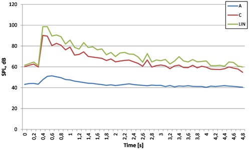
The results measured with C-weighting and the results measured unweighting – LIN are much higher (about 20-30 dBC). This fact demonstrates the definitely low-frequency nature of the spectra studied. A detailed spectral analysis for the maximum sound levels for shooting No. 2 (MW 300 kg) in the examined measuring points is shown in Figs. 2 and 4. In contrast, the A, C and LIN sound waveforms for which the maximum sound level value was determined are shown in Fig. 1 and 3.
Fig. 1Time courses of sound pressure level (SPL) on A, C, LIN filters. Place No. 1 (village 1), detonation No. 2.
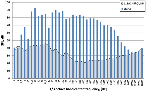
While analysing the drawings presenting spectra for maximum sound levels during each detonation, it should be stated that the largest distance between acoustic energy of explosion and acoustic background occurs in the frequency band from 12.5 Hz to approx. 6 kHz for the locality closer to the detonation (place No. 2), regardless of the weight used. However, for a further village (place No. 1), the largest acoustic energy of explosion from acoustic background occurs in the band from 12.5 Hz to approx. 2 kHz.
Fig. 2Spectra of maximum sound pressure level unweighted (LIN) – LMAX, sound pressure level of background (LBACKGROUND). Place No. 1 (village 1), detonation No. 2
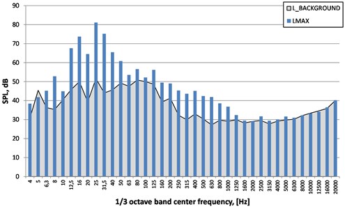
Fig. 3Time courses of sound pressure level (SPL) on A, C, LIN filters. Place No. 2 (village 2), detonation No. 2
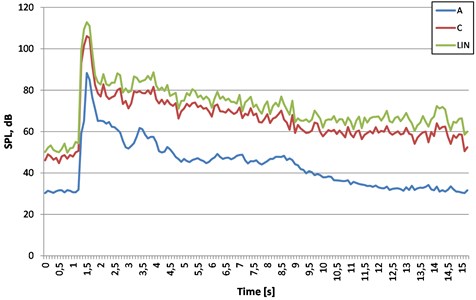
Fig. 4Spectra of maximum sound pressure level unweighted (LIN) – LMAX, sound pressure level of background (LBACKGROUND). Place No. 2 (village 2), detonation No. 2
Due to the fact that the measurements at all points were made simultaneously, it can be assumed that the weather conditions - temperature, humidity and atmospheric pressure were similar, only the direction and speed of the wind changed, and its effect at each point was significant but different. It was therefore assumed that for the measurements made, the uncertainty is in practice only with the wind. Based on the geometry of the terrain distribution of measurement points and the results obtained, it was determined that the average error (wind effect correction) on sound propagation was 2.2 dB/km. Standard uncertainty 1.8 dB/km, therefore the expanded uncertainty 3.1 km/dB (for the uniform distribution of wind direction). So, at the distance of 6/7 km the spread of results depending on the direction of the wind can be as much as 20 dB. This means that each time during measurements it is necessary to know the exact atmospheric conditions by means of sound propagation.
It should be stated that depending on the temperature and humidity of the air in other conditions in which detonation can take place, it is possible to expect changes in propagation conditions (air relaxation suppression up to 1.5 dB/km). Thus, at lower temperatures and higher humidity, the noise levels in the places in question will be slightly higher than at higher temperatures and dry air. In order to limit the extent of the adverse impact of noise from the blasting works in question, it is advisable to carry out these works on sunny days, preferably cloudless or with a slight cloudiness, windless. Avoid days with high humidity, low ceilings of clouds and wind in the direction of any places inhabited by people and animals.
6. Paraseismic vibration, airblast (AB)
Due to the fact that AB may also affect objects in the environment, during the measurement of AB, vibration measurements were also carried out in the ground and on building objects. Sensitivity thresholds on vibration meters are set at 0.3 mm/s, and for microphones at 10 Pa. Sample results of registration from detonation no. 3 at measuring stands are shown in Figs. 5 and 9.
While analysing the seismogram (Fig. 5) it can be stated that the time of signal input on the vibration meter and the pressure change record registered by the microphone occurred at the same time. This indicates that the transmitted signal was through the air, not through the ground (the seismic wave in the ground is much faster than airblast).
Fig. 5Seismogram and airblast pressure record. Place No. 1 (village 1), detonation No. 3
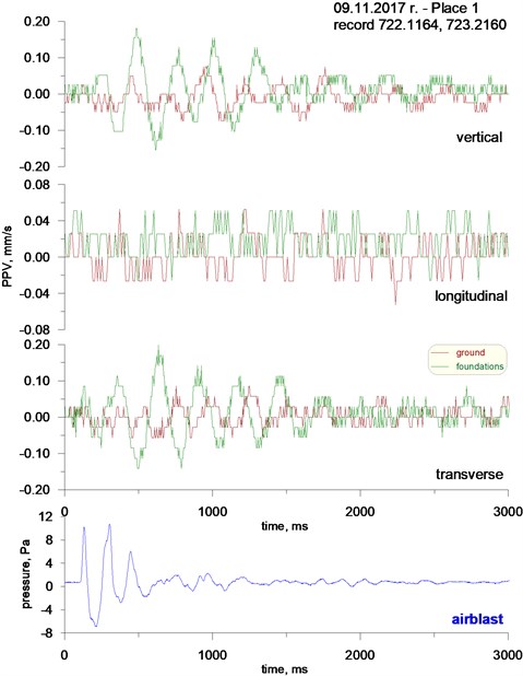
Fig. 6Spectra of the ground vibration sensor record (x, y, z). Place No. 1 (village 1), detonation No. 3
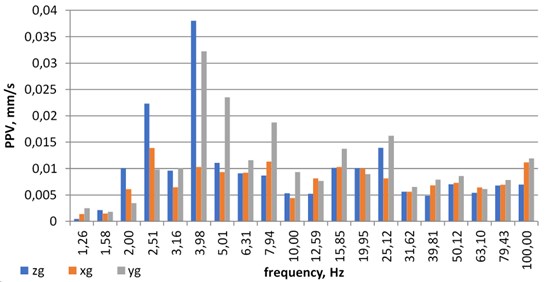
Fig. 7Spectra of the substructure vibration sensor record (x, y, z). Place No. 1 (village 1), detonation No. 3
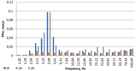
Fig. 8Spectrum of airblast microphone record. Place No. 1 (village 1), detonation No. 3
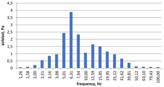
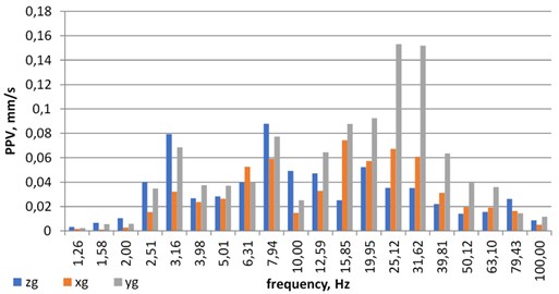
In case the apparatus was not equipped with a microphone, vibrations would not be recorded because their registered level was below the set sensitivity level. Figs. 6, 7 and 8 show frequency structures in 1/3 octave bands. The vibrations spectrum is dominated by lower frequencies in the 4 Hz range for the ground and substructure and 6.3 Hz for airblast. The same analysis was carried out for measurement point in village 2 (Figs. 9-12).
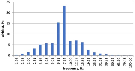
While analysing the seismogram (Fig. 6) it can be observed that the time of input being recorded by the vibration meter (mounted in the ground and on substructure) and the record of pressure changes registered by the microphone occurred at the same time - similar to the devices installed in the village 1. The signal input time is the same, so there is no transfer of seismic wave ground. In this station, the recorded vibration was greater than the threshold of sensitivity and it would register even in a situation where the microphone was not connected. The records were subjected to a 1/3 octave band analysis to examine the frequency structure of the signals. From Figs. 10 and 11, it can be concluded that the frequency structure of ground and substructure vibrations is more complex than in village 1. The spectra include higher frequencies 25 Hz and 31 Hz, which were not in the spectra of vibrations registered in village 1. In addition to higher frequencies there are also lower frequencies 3.16 Hz and 8 Hz. Frequency structures of AB recordings in village 1 and 2 are very similar to each other and are characterized by lower frequencies in the range of 6.3 Hz. The conducted impact tests and airblast hazards showed no possibility of damage on objects from blasting works in both locations and the possibility of making complaints about the inconvenience of shooting in the village 2.
Fig. 9Seismogram and airblast pressure record. Place No. 2 (village 2), detonation No. 3

Fig. 10Spectra of the ground vibration sensor record (x, y, z). Place No. 2 (village 2), detonation No. 3
Due to the fact that the impact was propagated by air, it is not possible to assess the impact of recorded vibrations on buildings in accordance with the guidelines of PN-B-02170: 2016-12 [19], which affects the impact of vibrations transmitted through the ground. This fact was confirmed by connecting the airblast pressure measuring microphone. Without this, it could not be clearly stated, because the record of vibrations in no way deviates from the records made during propagation of vibrations with ground. This situation poses a real threat that misinterpretation of the results may occur, and thus to the assessment of the impact of vibrations on buildings not in accordance with the guidelines described in this standard.
Fig. 11Spectra of the substructure vibration sensor record (x, y, z). Place No. 2 (village 2), detonation No. 3
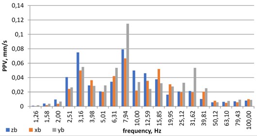
Fig. 12Spectrum of airblast microphone record. Place No. 2 (village 2), detonation No. 3.
7. Conclusions
The article presents, on the example of high-energy impulse measurements (surface blasting robots) comprehensive research related to the distribution of selected physical fields at a further distance. It should be emphasized that often these types of sources are located close to the housing and in operation can have a detrimental effect on both buildings and can cause serious inconvenience to people and animals. The threat is caused by the short-time high-energy shock wave - acoustic, air (airblast) and paraseismic. From the results of the measurements carried out and from the recommendations of the normative documents, it follows that when predicting an equivalent level of sound, A and its exceedances in relation to the permissible levels, it is necessary to know exactly the atmospheric conditions prevailing in the way of sound propagation. The analysis of registered vibrations on a construction site confirmed doubts as to the applicability of the PN-B-02170: 2016-12 standard [19], which concerns the impact on vibration buildings transferred through the ground, not through the air (pressure change). However, it remains doubtful whether the recorded impact by the vibration meters was an impact on the object and the ground, or whether it was only affecting the sensor itself. This doubt in case of not having information about all phenomena can lead to over interpretation of registered vibrations, and thus to erroneous assessment of impacts on buildings and people in buildings [27].
References
-
Pyra J., Sołtys A. Method for studying the structure of blast-induced vibrations in open-cast mines. Journal of Vibroengineering, Vol. 18, Issue 6, 2016, p. 3829-4840.
-
Mohd Nur Asmawisham Alel, Mark Ruben Anak Upom, Rini Asnida Abdullah, Mohd Hazreek Zainal Abidin Optimizing blasting’s air overpressure prediction model using swarm intelligence. Journal of Physics: Conference Series, Vol. 995, 2018, p. 012046.
-
He W., Chen J., Guo J. Dynamic analysis of subway station subjected to internal blast loading. Journal of Central South University Technology, Vol. 18, Issue 3, 2011, p. 917-924.
-
Wu C., Hao H. Modeling of simultaneous ground shock and airblast pressure on nearby structures from surface explosions. International Journal of Impact Engineering, Vol. 31, Issue 6, 2005, p. 699-717.
-
Ullah A., Ahmad F., Jang H. W., Kim S. W., Hong J.-W. Review of analytical and empirical estimations for incident blast pressure. KSCE Journal of Civil Engineering, Vol. 21, Issue 6, 2017, p. 2211-2225.
-
Alcudia A. D. Microphone and Geophone Data Analysis for Noise Characterization and Seismic Signal Enhancement. M.Sc. Thesis, Department of Geoscience, University of Calgary, 2009.
-
Babcock N. M. Microphone Suppression of Air-Noise on Geophones. M.Sc. Thesis, Faculty of the Department of Earth and Atmospheric Sciences, University of Houston, 2012.
-
Pyra J., Sołtys A., Winzer J. Remarks on effect of air shock wave on environment at works with use of MW (explosives). Przegląd Górniczy, Vol. 65, Issues 11-12, 2009, p. 94-102, (in Polish).
-
Steiner M. Classification of Signal Sources Based on Seismic and Acoustic Measurements. Diplomarbeit, Department für Geodäsie und Geoinformation Forschungsgruppe Geophysik der Technischen Universität Wien, 2015.
-
Weitzel W. R. Evaluation of Overpressure Wave Transition by Airblast Overpressure and Shock Wave Attenuation Analysis Using a Small Black Powder. Ph.D. Thesis, Mining Engineering, Lexington, Kentucky, Paper 17, 2014.
-
Margrave G., Kris Innanen K., Lawton D., Bancroft J., Lamoureux M., Lines L. CREWES 5-year research plan: Towards broadband multicomponent seismology and practical iterated inversion. CREWES Research Report, Vol. 25, 2013.
-
Brückl E. Classification of Signal Sources Based on Seismic and Acoustic Measurements. Department für Geodäsie und Geoinformation Forschungsgruppe Geophysik der Technischen Universität Wien, 2015.
-
Griffiths M. J., Oatfs J. A. H., Loard P. The propagation of sound from quarry blasting. Journal of Sound and Vibration, Vol. 60, Issue 3, 1978, p. 359-370.
-
Wszołek T., Kłaczyński M. Accuracy of assessing the level of impulse sound from distant sources, International Journal of Occupational Safety and Ergonomics (JOSE), Vol. 13, Issue 4, 2007, p. 433-440.
-
Regulation of the Minister of Environment dated 30 October 2014 (Official Journal No. 0, Item 1542). Annex No. 8, (in Polish).
-
Acoustics – Description, Measurement and Assessment of Environmental Noise – Part 2: Determination of Sound Pressure Levels. Standard No. ISO 1996-2:2017, International Organization for Standardization (ISO), Geneva, 2017.
-
Acoustics – Methods for The Description and Physical Measurement of Single Impulses or Series of Impulses. Standard No. ISO 10843:2002, International Organization for Standardization (ISO), Geneva, 2002.
-
Acoustics. Framework for Calculating a Distribution of Sound Exposure Levels for Impulsive Sound Events for the Purposes of Environmental Noise Assessment. Standard No. ISO 13474:2009, International Organization for Standardization (ISO), Geneva, 2009.
-
Evaluation of The Harmfulness of Buildings Vibrations Due to Ground Motion. Standard No. PN-B-02170:2016-12, Polish Committee for Standardization (PKN), Warszawa, 2016, (in Polish).
-
Deutsches Institut für Normung (DIN), Vibrations in Buildings – Part 1: Prediction of Vibration Parameters. Standard No. DIN 4015 -1:2001-06, Berlin, 2001.
-
Deutsches Institut für Normung (DIN), Vibrations in Buildings – Part 3: Effects on Structures. Standard No. DIN 4150-3:2016-12, Berlin, 2016.
-
British Standard (BS), Eurocode 8: Design of Structures for Earthquake Resistance – Part 1: General Rules, Seismic Actions and Rules for Buildings. Standard No. BS EN 1998-1:2004, London, 2004.
-
“ISEE Blasters’ Handbook. 18th edition, International Society of Explosives Engineers, 2011.
-
Stachura V. J., Siskind D. E., Engler A. J. Airblast Instrumentation and Measurement Technique for Surface Mine Blast. U.S. Bureau of Mines, Report of Investigations 8508, 2000.
-
Regulation of the Minister of Economy, Labor and Social Policy dated 9 July 2003 (Official Journal No. 163, Item 1577), (in Polish).
-
Regulation of the Minister of Environment dated 14 June 2007 (Official Journal No. 120, Item 826) amended in 01 October 2012 (Official Journal No. 0, Item 1109), (in Polish).
-
Evaluation of the Impact of Vibrations on People in Buildings. Standard No. PN-B-02171:2017-06, Polish Committee for Standardization (PKN), Warszawa, 2017, (in Polish).
Cited by
About this article

The work was created as part of the statutory research project of Department of Surface Mining and Department of Mechanics and Vibroacoustics AGH in Krakow.
